TCS15294R - Speaker Turbosound - Free user manual and instructions
Find the device manual for free TCS15294R Turbosound in PDF.
| Product type | 2-way passive loudspeaker |
| Brand | Turbosound |
| Model | TCS15294R |
| Dimensions (W x H x D) | 700 x 450 x 400 mm |
| Weight | 25 kg |
| Nominal impedance | 8 ohms |
| Power handling (RMS) | 400 W |
| Peak power | 1600 W |
| Frequency response | 45 Hz – 20 kHz |
| Sensitivity (1W/1m) | 97 dB |
| Input connectors | 2 x Neutrik SpeakON NL4MP |
| Enclosure material | Birch plywood |
| Grille | Perforated steel with powder coating |
| Installation type | Floor or pole mount |
| Powering | Passive (requires external amplifier) |
| Maintenance and cleaning | Clean with a dry cloth. Do not use liquid products. |
| Safety | Do not expose to rain or moisture. Disconnect before maintenance. |
| Spare parts and repairability | Contact authorized after-sales service. |
| Warranty | See terms at music-group.com/warranty |
| General information | User manual available for download in PDF format. |
Frequently Asked Questions - TCS15294R Turbosound
User questions about TCS15294R Turbosound
0 question about this device. Answer the ones you know or ask your own.
Ask a new question about this device
Download the instructions for your Speaker in PDF format for free! Find your manual TCS15294R - Turbosound and take your electronic device back in hand. On this page are published all the documents necessary for the use of your device. TCS15294R by Turbosound.
USER MANUAL TCS15294R Turbosound
natural_image
Four-panel black-and-white photo collage showing a music event hall, a cheering crowd, a control room with multiple speakers, and a silhouetted audience celebrating with raised fists (no visible text or symbols)ATHENS
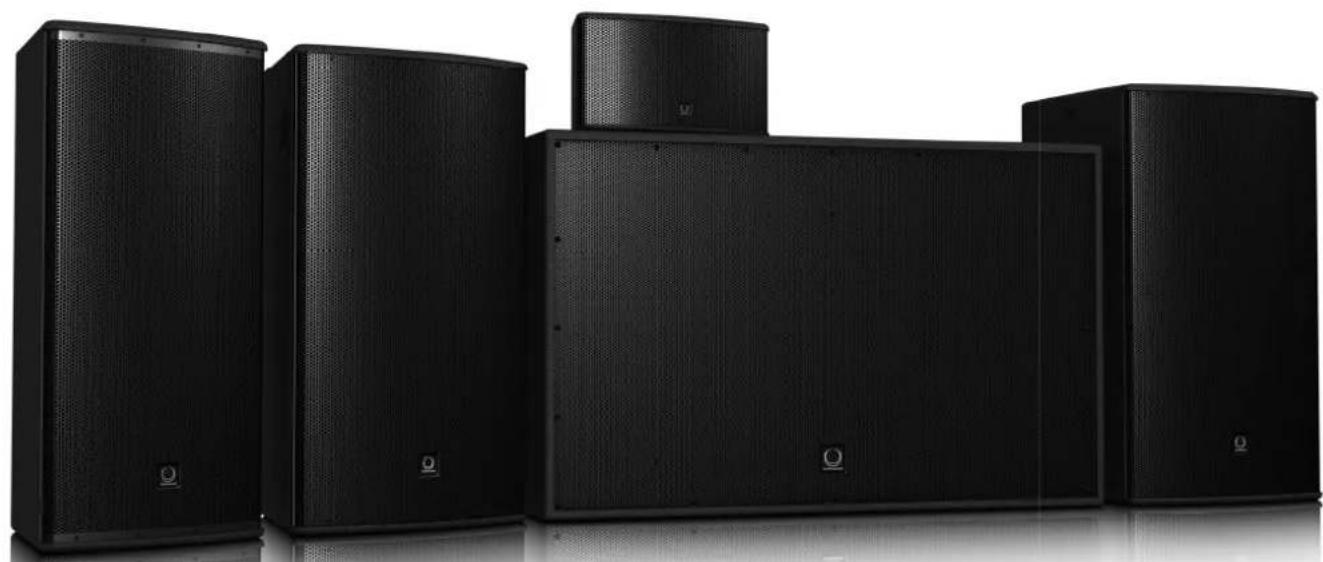
TCS Weather Resistant Series
TCS62-R (R-WH), TCS122/64-R (R-WH), TCS122/96-R (R-WH), TCS122/94-R (R-WH), TCS152/64-R (R-WH), TCS152/96-R (R-WH), TCS152/94-R (R-WH), TCS115B-R (R-WH), TCS218B-R (R-WH)
Arrayable 2 Way Full Range Loudspeakers for Installation Applications (Weather Resistant)
Quickstart Guide
natural_image
Exterior view of a set of black audio/video amplifiers (no text or symbols visible)2 TCS Passive R series Quick Start Guide
text_image
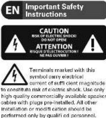
EN Important Safety Instructions CAUTION RISK OF ELECTRIC SHOCK? DO NOT OPEN ATTENTION RESIDENT TO THE EDITION NO HAS QUOTLY! Terminals marked with this symbol carry electrical current of sufficient client magnitude to constitute risk of electric shock. Use only high quality commercially available speaker cables with plug pre-installed. All other installation or modification should be performed only by qualified personnel.This symbol, wherever it appears, alerts you to the presence of uninsulated dangerous voltage inside the enclosure voltage that may be sufficient to constitute a risk of shock.
This symbol, wherever it appears, alerts you to important operating and maintenance instructions in the accompanying literature. Please read the manual.
Caution To reduce the risk of electric shock, do not remove the top cover for the rear section. No user serviceable parts inside. Refer servicing to qualified personnel.
Caution To reduce the risk of fi re or electric shock, do not expose this appliance to rain and moisture. The apparatus shall not be exposed to dropping or splashing liquids and no objects filled with liquids, such as vases, shall be placed on the apparatus.
Caution These service instructions are for use by qualified service personnel only. To reduce the risk of electric shock do not perform any servicing other than that contained in the operation instructions, Repairs have to be performed by qualified service personnel.
- Read these instructions.
- Keep these instructions.
- Host all warnings.
- Follow all instructions.
- Do not use this apparatus near water.
- Clean only with dry cloth.
- Do not block any ventilation openings. Install in accordance with the manufacturer's instructions.
-
Do not install near any heat sources such as radiators, heat registers, stoves, or other apparatus (including amplifiers) that produce heat.
-
Do not defeat the safety purpose of the polarized or grounding-type plug. A polarized plug has two blades with one wider than the other. A grounding-type plug has two blades and a third grounding prong. The wide blade or the third prong are provided for your safety. If the provided plug does not fit into your outlet, consult an electrician for replacement of the obsolete outlet.
-
Protect the power cord from being walked on or pinched particularly at plugs, convenience receptacles, and the point where they exit from the apparatus.
-
Use only attachments/accessories specified by the manufacturer.

- Use only with the cart, stand, tripod, bracket, or table specified by the manufacturer, or sold with the apparatus. When a cart is used,
moving the carfaoperatus combination to avoid injury from tip-over.
13. Unplug this apparatus during lightning storms or when unused for long periods of time.
-
Refer all servicing to qualified service personnel. Servicing is required when the apparatus has been damaged in any way, such as power supply cord or plug is damaged, liquid has been spilled or objects have fallen into the apparatus, the apparatus has been exposed to rain or moisture, does not operate normally, or has been dropped.
-
The apparatus shall be connected to a MAINS socket outlet with a protective washing connection.
-
Where the MAIN5 plug or an appliance coupler is used as the disconnect device, the disconnect device shall remain readily operable.

- Correct disposal of this product: This symbol indicates that this product must not be disposed of with household waste, according to the WEEE Directive (2012/19/EUI) and your national law.
This product should be taken to a collection center licensed for the recycling of waste electrical and electronic equipment (EEE). The mishandling of this type of waste could have a possible negative impact on the environment and human health due to potentially hazardous substances that are generally associated with EEE. At the same time, your cooperation in the correct disposal of this product will contribute to the effi client use of natural resources. For more information about where you can take your waste equipment for recycling, please contact your local city offi ca, or your household waste collection service.
LEGAL DISCLAIMER
MUSIC Group accepts no liability for any loss which may be suffered by any person who relies either wholly or in part upon any description, photograph, or statement contained herein. Technical specific cations, appearances and other information are subject to change without notice. All trademarks are the property of their respective owners. MIDAS, KLARK TEKNIK, TURBOSOUND, BEHRINGER, BUGERA and DDA are trademarks or registered trademarks of MUSIC Group IP Ltd. © MUSIC Group IP Ltd. 2014 All rights reserved.
LIMITED WARRANTY
For the applicable warranty terms and conditions and additional information regarding MUSIC Group's Limited Warranty, please see complete details online at music group.com/warranty.
BESCHRÄNKTE GARANTIE
Thank you for choosing a TURBOSOUND loudspeaker product for your application. If you would like further information about this or any other TURBOSOUND product, please visit our website at turbosound.com.
Unpacking the Loudspeaker
After unpacking the unit please check carefully for damage. If damage is found, please notify your supplier at once. You, the consignee, must instigate any claim. Please retain all packaging in case of future re-shipment.
System Requirements – Passive and Bi-amped Loudspeakers
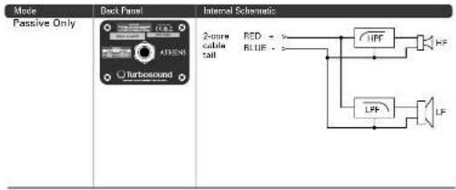
TCS62-R 2-way loudspeaker operates as a passive system and requires only one amplifier channel. The input signal is divided between the low frequency and high-frequency drivers internally with a passive crossover.
TCS122-R and TCS152-R are switchable passive / bi-amp 2-way loudspeakers. Passive and bi-amp modes are controlled by an internal switch. Passive operation (full range or with a subwoofer) requires 1 amplifier channel and 1 controller channel. The input signal is divided between the low-frequency and high-frequency drivers internally with a passive crossover. Bi-amp operation (full range or with a subwoofer) requires 2 amplifier channels and 2 controller channels, one for low frequencies one for high frequencies. The input signal is divided between the low frequency and high frequency driver in the controller and the individual amplified signals are fed to the speaker input.
TCS218B-R subwoofer has a 4-wire input to allow operation in parallel or discrete modes. Parallel operation is achieved by wiring inputs 1 and 2 in parallel and requires only 1 amplifier channel and 1 controller channel. Discrete operation is achieved by wiring inputs 1 and 2 separately, requiring 2 amplifier channels and 2 controller channels.
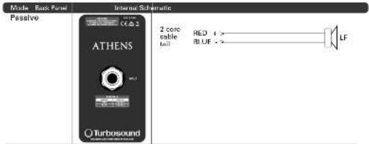
TCS115B subwoofer operates as a passive system and requires only one amplifier channel.
Correct controller settings for all models, horn variants and operation with subwoofers can be downloaded from the website, and are also available as presents for the LMS series controllers.
TCS weather-resistant loudspeakers are equipped with a 2 metre 4-core cable tail for connection to your chosen cabling infrastructure, with the exception of TCS62-R and TCS115B-R, which use a 2-core cable tail. To avoid wasting amplifier power, you should use heavy-duty speaker cable, with a minimum wire size of 1.5 mm² (16 AWG), and preferably 2.5 mm² (14 AWG) for longer runs. Use larger wire sizes for TCS218B-R and speakers wired in parallel. For extreme cable lengths, be aware of cable impedance and resistive losses. Always observe the correct polarity.
EN
Amplifi er Considerations
The TCS series loudspeakers are optimised for use with the TURBOSOUND T series amplifiers with the LMS series controllers. A full range of DSP settings to suit any configuration are provided for download on the TURBOSOUND website. The use of third party amplification and processing is only advised using the matrix of manual settings as well as the limiter calculator provided on the TURBOSOUND website.
The TCS series loudspeaker enclosures should be driven by high quality power amplifiers designed for true professional use. Power amplifiers should be capable of delivering long term broadband power equal
to half the loudspeaker's peak power rating at its stated nominal impedance. The use of underpowered amplifiers must be avoided as heavily clipped signals can cause permanent loudspeaker damage.
Limiters, crossovers and equalisation points must be set in accordance with the settings provided on the TURBOSOUND website. This will ensure the optimum sound quality and long-term reliability as well as protection from damage.
2 meter 4-core cable tails are provided, allowing options for passive, bi-amp, parallel and discrete operation, with the exception of TCS62-R and TCS115B-R, which use a 2-core cable tail.
Recommended Minimum Amplifier Power
| Model TCS82-R TCS122-R TCS153-R TCS165-R TCS216R-R | ||||||||||
| Mode | Passive | Passive | Bi-amp LF | Bi-amp LF | Passive | Bi-amp LF | Bi-amp HF | Passive | Passive | |
| Impedance | 8 Ohms | 8 Ohms | 8 Ohms | 8 Ohms | 8 Ohms | 8 Ohms | 9 Ohms | 9 Ohms | 4 Ohms | |
| Minimum Amplifier Power | Continuous RMS | 175 W | 600 W | 600 W | 75 W | 800 W | 600 W | 75 W | 500 W | 1000 W |
| Pack | 700 W | 2400 W | 2400 W | 750 W | 2400 W | 2400 W | 750 W | 2000 W | 6400 W | |
Outdoor Applications
TCS weather-resistant products are designed to provide robust protection against the elements when used outdoors in harsh environments. The cabinet is fully sealed inside and out, protected with a weather-resistant paint finish, and the plated and outdoor powder-coated perforated steel grille backed with reticulated foam resists the impact of showers. Hard wired speaker connection is made via a 4 or 2-core cable tail fitted through a weather-sealed cable gland mounted on an aluminium connector plate. Stainless steel external fixings are used throughout. Internally, the drivers are treated to resist moisture absorption while the internal corner brackets are zinc plated and outdoor powder-coated.
While TCS series loudspeakers with the "R" suffix are constructed for outdoor use, care should be taken when installing these loudspeakers outdoors in coastal areas where high salinity and extreme temperature variations are present in addition to high humidity and UV light exposure.
Loudspeakers must always be mounted with a downward angle. Do not allow loudspeakers to become fully immersed in water at any time. Routine inspection and maintenance programs must be carried out on a regular basis and parts replaced as necessary to provide continued satisfactory performance.
Connections
TCS62-R
text_image
Mode Passive Only Deck Panel Internal Schematic 2-core cable tail RED - - BLUE - - LFP HF LFTCS122-R, TCS152-R
| Maine | Back Panel | Internal Schematic |
| Passive (Internal Switch) | ATHENS Turbosound | 4-core cable tail RED + BLUE YELLOW N/C GREEN N/C HPF LF |
| BI-Amp (Internal Switch) | ATHENS Turbosound | 4-core cable tail RED LOW + BLUE LOW- YELLOW HIGH - GREEN HIGH - |
EN
12 TCS Passive R series Quick Start Guide
EN
TCS115B-R
text_image
Mode: Back Panel Passive Internal Schematic 2 core able load RED 1 > - BLUE > > LF ATHENS TurbosoundTCS218B-R
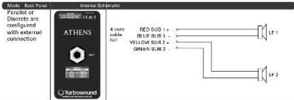
text_image
Mode Back Panel Internal Schematic Parallel or Discrete are configured with external connection ATHENS Turbosound 4 coro mable tail RED SUB 1 + BLUE SUB 1 - YELLOW SUB 2 - GREEN SUB 2 - LF 1 LF 213
Mounting and Fixing
The table below summarises the rigging parts or kits required for various applications, and some examples of the possible rigging options are illustrated.
TCS series cabinets are designed with multiple internal rigging points to suit many possible mounting methods in permanent installations. All cabinets can be simply suspended using optional M8 or M10 shoulder eyebolts coupled to the internal rigging points provided. Remove the appropriate countersunk screws and replace them with eyebolts, which must have a thread length of at least 18mm. Use the rear rigging point to angle the cabinet for optimum room coverage. Cabinets may be hung upside down if required. Turbosound WB-20, WB-55 and CB-55 wall and ceiling brackets are optionally available for TCS series cabinets, and these are also compatible with OmniMount ^4 wall and ceiling brackets which use 60 mm x 60 mm hole spacing.
| Model Wall Ceiling Drawift E Array Kit Eyeamps | ||||
| TC562 R | WB-20TC562 SQ | CB-56TC562 SB | TC562 SB MB Thread | |
| TC5122-WB-66 CO-55 | TC5122-FPTCS-FK1TCS-FK2 | CD-10-40 | ||
| TC5162-WB-66 CO-55 | TC5162-FPTCS-FK1TCS-FK2 | CD-10-40 | ||
| TC51158.R | TC5115-FPTCS-FK3 | EB-10-40 | ||
| TC5-R Subscribers EB-10-40 | ||||
Some typical examples of the possible rigging options are shown here:
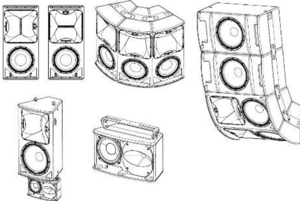
natural_image
Technical line drawings of various speaker modules and housing components (no text or labels)14 TCS Passive R series Quick Start Guide

TCS Series Flying Components
Wall and Ceiling Brackets
To install a loudspeaker using Turbosound wall and ceiling brackets, first separate the brackets into their wall/ceiling plate and speaker plate component parts. Remove the countersunk bolts on the rear panel of the cabinet. Attach the speaker plate to the cabinet with the bolts supplied. Fix the wall/ceiling plate in the venue using appropriate fixings (not supplied). Lift the loudspeaker on to the wall plate and re-assemble the bracket parts, adjust the vertical angle and tighten all bolts.
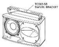
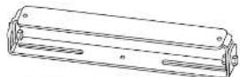
Downfi II Applications
The TCS62-R can be mounted underneath a TCS122-R or TCS152-R cabinet to provide downfi II coverage using the TCS62-SB swivel bracket. First disassemble the swivel bracket into its component parts. Remove the countersunk bolts from the bottom panel of the TCS152-R cabinet and fit the section with the elongated holes using the fixings supplied. Remove the countersunk bolts on the top panel and fit the swivel bracket using the supplied fixings. Re assemble the swivel bracket, angle as appropriate and tighten all fixings.
To install the TCS62-R in a ceiling-mount application, separate the component parts as above, and fix the top section to the ceiling with appropriate fixings (not supplied). Fit the other half to the TCS62-R cabinet, re-assemble the bracket, angle as appropriate and tighten all fixings.
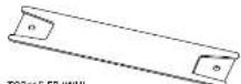
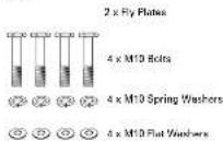
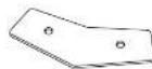
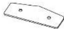
Loudspeaker Arrays and Clusters
An array of two or more cabinets requires the use of kits of flyplates and inter-cabinet couplers, which are fixed to the cabinet sides through the M10 rigging points and assembled together in a 'daisy chain' fashion to build up the required array. For all loudspeaker arrays consisting of two or more cabinets:
The number of inter cabinet coupler kits required = the number of boxes - 1. The number of flyplate kits required = the number of boxes.
Illustrated here are the components parts available for TCS cabinets:
TCS62-SB (WHO)
Swivel bracket for TCS62-R
Contents:
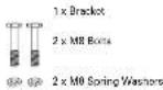
2 x MB Flat Washers
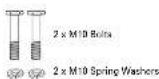
2 x M10 Flat Washers
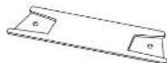
TCS 162 FP IWHI
Fly Plate Kit for TCS 152-R
Contents:
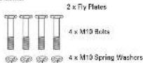
4 x M10 Flat Washers
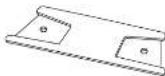
TCS122 FP (WH)
Fly Plate Kit for TCS122 R
Contents:
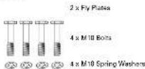
4 x M10 Flat Washers
TCS115-FP (WH)
Fly Plate Kit for TCS1158-R
Contents.
TCS-FK1 (WHI)
Inter-Cabinet Coupler Kit for TCS122-R or TCS152-R
Contents:
2×CC
TCS-FK3 (WH)
Inter-Cabinet Coupler Kit for TCS115B-R
Contents
2×10C
TCS-FK2 (WH)
Inter-Coumarist Couplor Kit for TCS122-R or TCS152-R
Contents:
2×CC

ER-10-40
Eysboh M10 x 40mm
Contents
1 x Eyebolt
16 TCS Passive R series Quick Start Guide
EN
Suspending with Eyebolts
TCS cabinets can be suspended using optional eyebolts coupled to the internal rigging points provided on the top, bottom and sides and back. The simplest method is to use the two rigging points on the top and a single pull-back rigging point in the centre of the rear panel.
Remove the appropriate countersunk screws and replace them with shoulder cycbolts, which must have a thread length of at least 18 mm. Use the rear rigging point to angle the cabinet for optimum room coverage. Cabinets may be hung upside down if required.
IMPORTANT NOTE FOR ALL INSTALLATION METHODS: The mounting of a permanently installed sound system may be dangerous unless undertaken by qualified personnel with the required experience and certification to perform the necessary tasks. Walls, floors or ceilings must be capable of safely and securely supporting the actual load. The mounting accessory used must be safely and securely fixed both to the loudspeaker and to the wall, floor or ceiling.
When mounting rigging components on walls, floors or ceilings, ensure that all fixings and fasteners used are of an appropriate size and load rating. Wall and ceiling claddings, and the construction and composition of walls and ceilings, all need to be taken into account when determining whether a particular fixing arrangement can be safely employed for a particular load. Cavity plugs or other specialist fixings, if required, must be of an appropriate type, and must be fitted and used in accordance with the maker's instructions.
The operation of your speaker cabinet as part of a flown system, if installed incorrectly and improperly, can potentially expose persons to serious health risks and even death. In addition, please ensure that electrical, mechanical and acoustic considerations are discussed with qualified and certified (by local state or national authorities) personnel prior to any installation or flying.
Make sure that speaker cabinets are set up and flown by qualified and certified personnel only, using dedicated equipment and original parts and components delivered with the unit. If any parts or components are missing please contact your Dealer before attempting to set up the system.
Be sure to observe the local, state and other safety regulations applicable in your country. MUSIC Group, including the MUSIC Group companies listed on the enclosed "Service Information Sheet", assumes no liability for any damage or personal injury resulting from improper use, installation or operation of the product. Regular checks must be conducted by qualified personnel to ensure that the system remains in a secure and stable condition. Make sure that, where the speaker is flown, the area underneath the speaker is free of human traffic. Do not fly the speaker in areas that can be entered or used by members of the public.
Speakers create a magnetic field, even if not in operation. Therefore, please keep all materials that can be affected by such fields (discs, computers, monitors, etc) at a safe distance. A safe distance is usually between 1 and 2 metres.
Rotating the HF horn pattern
The high frequency horn in all TCS122-R and TCS152-R models can be rotated through 90^ in order to swap the horizontal and vertical dispersion patterns, particularly useful when assembling clusters or for example to retain the original dispersion when the cabinet is installed in a horizontal orientation.
- Place the cabinet on its back on a suitable work surface. Take care of the protruding cable gland.
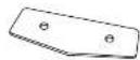
- Remove the 10 posi-drive screws that hold the grille in place and set the grille aside (fig 1).
- Remove and disconnect the bass driver (fig 2) to access the compression driver retaining brace, making a note of the bass driver polarity for later reconnection.
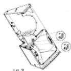
- Reach in through the bass driver cavity and loosen the two wing nuts securing the compression driver retaining brace (fi g 3).
- Remove the horn fixing screws that secure the horn to the enclosure and lift out the horn and compression driver assembly (fig 4). (If required for servicing or replacement, disconnect the cables from the compression driver, making a note of the polarity for later reconnection.)
- Rotate the horn to achieve the desired coverage pattern (if g 5).
- Re-assemble the cabinet and drivers by reversing steps 1-5.
- If the compression driver cables have been disconnected, reconnect the cables while observing the correct polarity (white cable to the -ve terminal, black cable to the -ve terminal).
- Place the horn and compression driver back into the cabinet, making sure that the driver cables pass underneath the compression driver retainer and that the compression driver fits squarely back into the retaining brace.
- Tighten the wing nuts back onto the compression driver retaining brace (fi g 3).
- Replace the horn fixing screws and tighten to secure the horn back into the enclosure (fig 4).
- Reconnect the bass driver cables, observing the correct polarity (red cable to the +ve terminal, blue cable to the -ve terminal).
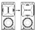
- Check all components and confirm the horn orientation is correct (fi g 6).
- Replace the grille (fig 1) and phase check the cabinet before use.
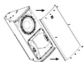
Fig. 1
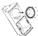
Fig.2
BEFORE AFTER
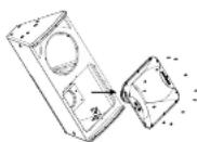
Fig.4 Fig.5
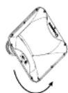
Fig.6
EN
EN Technical Specifications
| TCS62-R I-WH | TCS122/64-R I-WH | TCS122/94-R (-WH) | |
| System | |||
| Frequency response | 60 Hz - 20 kHz x 3 dB50 Hz - 20 kHz 10 dB | 50 Hz - 18 kHz x 3 dB45 Hz - 20 kHz 10 dB | 50 Hz - 18 kHz x 3 dB45 Hz - 20 kHz 10 dB |
| Nominal dispersion | 100° H x 67° V @ 6dB points, rotatable | 60° H x 40° V @ 6 dB points, rotatable | 90° H x 40° V @ 6 dB points, rotatable |
| Directivity factor (IQ) | 12.8 18.3 12.9 8.7 18.3 12.9 8.7 | ||
| Directivity Index (DII) | 11.1 12.6 11.1 9.4 12.6 11.1 9.4 | ||
| Power handling IIECI | |||
| Passive | 175 W continuous, 200 W peak | 600 W continuous, 2400 W peak | 600 W continuous, 2400 W peak |
| BI-amp | - | LF:500 W continuous, 2400 W peakHF:75 W continuous, 300 W peak | LF:500 W continuous, 2400 W peakHF:75 W continuous, 300 W peak |
| Sensitivity | 90 dB II W @ 1 ml | 90 dB II W @ 1 ml | 90 dB II W @ 1 ml |
| Maximum SPL | |||
| Passive | 112.5 dB continuous, 118.5 dB peak | 124 dB continuous, 130 dB peak | 124 dB continuous, 130 dB peak |
| BI-amp | - | LF: 126 dB continuous, 130 dB peakHF: 128 dB continuous, 134 dB peak | LF: 126 dB continuous, 130 dB peakHF: 128 dB continuous, 134 dB peak |
| Impedance | |||
| Passive | 8 Ω | 6 Ω | 8 Ω |
| BI-amp | - | LF: 8 ΩHF:6 Ω | LF:8 ΩHF:6 Ω |
| Crossover type | Passive | Passive / BI amp, internally switchable | Passive / BI amp, internally switchable |
| Components | 1 x 6" x 162 mm LF driver1 x 1" x 25 mm HF compression driver | 1 x 12" x 312 mm LF driver1 x 1.6" x 36 mm HF compression driver | 1 x 12" x 312 mm LF driver1 x 1.6" x 36 mm HF compression driver |
| Enclosure | |||
| Connectors | 2 core captive cable tail | 4-core captive cable tail | 4 core captive cable tail |
| Wiring | |||
| Passive RodBlue input + / | - | RodBlue input + / -YellowGreen NC | RodBlue input + / -YellowGreen FC |
| BI-amp | RodBlue LF + / -YellowGreen HF - / - | RodBlue LF + / -YellowGreen HF - / - | |
| Dimensions (HWD) | 224 x 402 x 198 mm(19.8 x 15.8 x 7.8") | 834 x 399 x 425 mm(32.8 x 15.7 x 16.7") | 834 x 399 x 425 mm(32.8 x 15.7 x 16.7") |
| Net weight | 7.3 kg (16.1 lbs) | 26.9 kg (59.3 lbs) | 26.9 kg (59.3 lbs) |
| Construction | 12 mm W/9 birch plywood | 15 mm W/9 birch plywood | 15 mm W/9 birch plywood |
| Finish | Semi-mut black paint white optional | Semi-mut black paint white optional | Semi-mut black paint white optional |
| Grille | Powder-coated perforated steel | Powder-coated perforated steel | Powder-coated perforated steel |
| Flying hardware | M/8 X 3, M/8 X 2 Points | M/10 x 9, M/8 X 8 Points | M/10 x 8, M/8 X 8 Points |
| Accessories | |||
| TCS62-50 WHOaxivel bracket for TCS82 | TCS 122-HP (WH)e y plate kit for TCS 122TCS-FK1 WHO inter cabinet couplerkit for TCS 122 or TCS 152TCS-FK2 (WH) inter-albinedoupler kit for TCS 158 withTCS 122 or TCS 152 | TCS 122-HP (WH)ty plate kit for TCS 122TCS-FK1 WHO inter cabinet couplerkit for TCS 122 or TCS 152TCS-FK2 (WH) inter-albinedoupler kit for TCS 158 withTCS 122 or TCS 152 | |
| TCS122/96-R (-WH) | TCS152/64-R (-WH) | TCS152/94-R (-WH) | TCS152/96-R (-WH) |
| 50 Hz - 18 kHz ±3 dB45 Hz - 20 kHz / 10 dB | 41 Hz - 18 kHz ±3 dB26 Hz - 20 kHz / 10 dB | 41 Hz - 18 kHz ±3 dB26 Hz - 20 kHz / 10 dB | 41 Hz - 18 kHz ±3 dB26 Hz - 20 kHz / 10 dB |
| 97 H x 60" V @ 6 dB points, rotatable | 60" x 40" V @ 6 dB points, rotatable | 90" x 40" V @ 6 dB points, rotatable | 90" H x 60" V @ 6 dB points, rotatable |
| 600 W continuous, 2400 W peakLF-600 W continuous, 2400 W peakHF-75 W continuous, 300 W peak | 600 W continuous, 2400 W peakLF-900 W continuous, 2400 W peakHF-75 W continuous, 300 W peak | 600 W continuous, 2400 W peakLF-900 W continuous, 2400 W peakHF-75 W continuous, 300 W peak | 600 W continuous, 2400 W peakLF-900 W continuous, 2400 W peakHF-7.5 W continuous, 300 W peak |
| 90 dB IT W @ 1 ml | 97 dB IT W @ 1 ml | 97 dB IT W @ 1 ml | 97 dB IT W @ 1 ml |
| 124 dB continuous, 130 dB peakLF - 124 dB continuous, 130 dB peakHF - 128 dB continuous, 134 dB peak | 125 dB continuous, 131 dB peakLF - 125 dB continuous, 131 dB peakHF - 128 dB continuous, 134 dB peak | 125 dB continuous, 131 dB peakLF - 125 dB continuous, 131 dB peakHF - 128 dB continuous, 134 dB peak | 125 dB continuous, 131 dB peakLF - 125 dB continuous, 131 dB peakHF - 128 dB continuous, 124 dB peak |
| 0 ΩLF: 8 ΩHF: 6 Ω | 8 ΩLF: 8 ΩHF: 6 Ω | 0 ΩLF: 8 ΩHF: 6 Ω | 8 ΩLF: 8 ΩHF: 6 Ω |
| Passive / Bi amp, internally switchable1 x 12" 2/12 mm LF driver1 x 1.2" 3/6 mm HF compression driver | Passive / Bi amp, internally switchable1 x 15" 2/64 mm LF driver1 x 1.4" 3/6 mm HF compression driver | Passive / Bi amp, internally switchable1 x 15" 2/64 mm LF driver1 x 1.4" 3/6 mm HF compression driver | Passive / Bi amp, internally switchable1 x 15" 2/64 mm LF driver1 x 1.4" 3/6 mm HF compression driver |
| 4 core captive cable tail | 4 core captive cable tail | 4 core captive cable tail | 4 core captive cable tail |
| RedBlue Input +/- Yellow/Green NCRedBlue LF +/- Yellow/Green HF +/- | RedBlue Input +/- Yellow/Green NCRedBlue LF +/- Yellow/Green HF +/- | RedBlue Input +/- Yellow/Green NCRedBlue LF +/- Yellow/Green HF +/- | RedBlue Input +/- Yellow/Green NCRedBlue LF +/- Yellow/Green HF +/- |
| 834 x 368 x 425 mm(22.8 x 15.7 x 16.7")20.9 kg (59.3 lbst | 834 x 473 x 451 mm(32.8 x 18.6 x 17.8")20.6 kg (63.1 lbst | 834 x 473 x 451 mm(32.8 x 18.6 x 17.8")20.6 kg (63.1 lbst | 834 x 473 x 451 mm(32.8 x 18.6 x 17.8")20.6 kg (63.1 lbst |
| 15 mm (W)/ Bhirch plywood | 15 mm (W)/ Bhirch plywood | 15 mm (W)/ Bhirch plywood | 15 mm (W)/ Bhirch plywood |
| Semi mult black paint white optional | Semi mult black paint (white optional) | Semi mult black paint (white optional) | Semi mult black paint (white optional) |
| Powder-coated perforated steel | Powder-coated perforated steel | Powder-coated perforated steel | Powder-coated perforated steel |
| M10 x 9, M8 X 8 Points | M10 x 9, M8 X 8 Points | M10 x 9, M8 X 8 Points | M10 x 9, M8 X 8 Points |
| TCS122-PP (WH)fly plate kit for TCS122TCS FK1 (WH) inter cabinet coupler kit for TCS122 or TCS152TCS FK2 (WH) inter-substit copper kit for TCS158 with TCS122 or TCS152 | TCS152-PP (WH)fly plate kit for TCS152TCS FK1 (WH) inter cabinet coupler kit for TCS122 or TCS152TCS FK2 (WH) inter-substit copper kit for TCS158 with TCS122 or TCS152 | TCS152-PP (WH)fly plate kit for TCS152TCS FK1 (WH) inter cabinet coupler kit for TCS122 or TCS 162TCS FK2 (WH) inter-substit copper kit for TCS158 with TCS122 or TCS152 | TCS152-PP (WH)fly plate kit for TCS152TCS FK1 (WH) inter-coimot coupler kit for TCS122 or TCS162TCS FK2 (WH) inter-coimot coupler kit for TCS158 with TCS122 or TCS152 |
20 TCS Passive R series Quick Start Guide
EN
Technical Specifications
TCS115B-R (-WH) TCS218B-R (-WH)
| System | ||
| Frequency response | 45 Hz - 150 Hz ± 3 dB40 Hz - 200 Hz - 10 dB | 33 Hz - 200 Hz ± 3 dB27 Hz - 200 Hz - 10 dB |
| Nominal dispersion | Hair space wall space | |
| Power handling IECI | 500 W continuous, 2000 W peak 1000 W continuous, 6400 W peak | |
| Sensitivity | 90 dB (1 W @ 1 to 30 dB (1 W @ 1 or | |
| Maximum SPL | 124 dB continuous, 130 dB peak 131 dB continuous, 137 dB peak | |
| Impedance | 9 Ω | Parallel 4 Ω Discrete 8 Ω x 2 |
| Components | 1 x 15" 100" mmol LF driver 2 x 18" 1400 mmol LF driver | |
| Endurance | ||
| Connectors | 2-core capitive cable tail 4-core capitive cable tail | |
| Wiring | ||
| Parallel / No switch RealBlue input | - | RedBlue input 1 / YellowGreen Link 1 / RedBlue input 1 / YellowGreen Input 2 + / - |
| Discrete | - | |
| Dimensions IIHWDI | 834 x 469 x 482 mm(32.9 x 16.5 x 7.8") | 1130 x 210 x 730 mm(44.5 x 29.0 x 28.8") |
| Net weight | 33.9 kg (74.2 lbel) | 94 kg (207.2 lbel) |
| Construction | 15 mm PV/7 birch plywood | 18 mm PV/7 birch plywood |
| Finish | Semi matt block paintwhistle odonali | Semi matt black paintwhistle optionali |
| Grille | Puede-cutated perforated steel | Puede-cutated perforated steel |
| Flying hardware | M 10 x 8 | M 10 x 8 |
| Accessories | ||
| TCS116 FP WHII y plate kit for TCS115TCS-FK2 WHII inter-cabinetcooper pit for TCS115B withTCS122 or TCS152TCS-FK3 WHII inter-cabinocopper pit for TCS115B | ||
Other important information
EN
Important information
-
Register online. Please register your new MUSIC Group equipment right after you purchase it by visiting turboscound.com. Registering your purchase using our simple online form helps us to process your repair claims more quickly and affi clently. Also, read the terms and conditions of our warranty, if applicable.
-
Malfunction. Should your MUSIC Group Authorized Reseller not be located in your vicinity, you may contact the MUSIC Group Authorized Further for your country listed under "Support" at turbosound.com. Should your country not be listed, please check if your problem can be dealt with by our "Online Support" which may also be found under "Support" at turbosound.com. Alternatively, please submit an online warranty claim at turbosound.com BEFORE returning the product.
-
Power Connections. Before plugging the unit into a power socket, please make sure you are using the correct mains voltage for your particular model. Faulty fuses must be replaced with fuses of the same type and rating without exception.
EN