XDM6001 - Receiver JL Audio - Free user manual and instructions
Find the device manual for free XDM6001 JL Audio in PDF.

| Product Type | Monoblock Class D Amplifier |
| Brand | JL Audio |
| Model | XDM6001 |
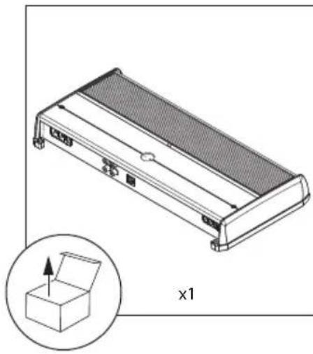
| Dimensions (W x D x H) | 374 x 180 x 52 mm |
| Power Supply | 12 V DC, negative ground |
| Recommended Fuse | 80 A (installed within 45 cm of battery) |
| RMS Power (14.4 V, <1% THD) | 600 W x 1 @ 4 Ω 800 W x 1 @ 3 Ω 1000 W x 1 @ 2 Ω |
| RMS Power (12.5 V, <1% THD) | 500 W x 1 @ 4 Ω 650 W x 1 @ 3 Ω 800 W x 1 @ 2 Ω |
| Frequency Response | 7 Hz – 500 Hz (+0, -1 dB) |
| Signal-to-Noise Ratio | >83 dB (ref. nominal power, A-weighted) |
| Damping Factor | 1000 @ 50 Hz / 4 Ω |
| Inputs | 2 balanced-differential RCA (stereo) inputs, 200 mV – 4 V RMS |
| Low-Pass Filter | Active, 12 or 24 dB/octave, 50 – 500 Hz, defeatable |
| Remote Control | HD-RLC or MHD-RLC (optional) |
| Topology | Ultra-fast NexD™ Class D |
| Protections | Overheating, overcurrent, low voltage |
| LED Indicator | Green: normal operation Red: overheating Orange: overcurrent Flashing green: startup Off: low voltage |
| Turn-On Mode | Remote (12 V switched), Offset (DC detection), Signal (audio detection) |
| Required Power Cable | 4 AWG copper (minimum) |
| Use | 12 V negative ground systems (automotive/marine) |
| Safety Instructions | Do not immerse; install in a dry, ventilated location; mount securely; use a fuse near battery |
| Subwoofer Output | Mono, two positive and two negative terminals |
| Preamp Outputs | 2 RCA pass-through outputs (not affected by filter) |
Frequently Asked Questions - XDM6001 JL Audio
User questions about XDM6001 JL Audio
0 question about this device. Answer the ones you know or ask your own.
Ask a new question about this device
Download the instructions for your Receiver in PDF format for free! Find your manual XDM6001 - JL Audio and take your electronic device back in hand. On this page are published all the documents necessary for the use of your device. XDM6001 by JL Audio.
USER MANUAL XDM6001 JL Audio
- Installation requires appropriate tools and safety equipment. Professional installation is recommended.
- This product is water-resistant. Do not submerge or subject to high-pressure water spray.
- Before installation, turn off the audio system and disconnect the battery system from the audio system.
- When possible, install in a dry, well-ventilated location that does not interfere with factory-installed systems. If a dry environment is not available, a location that is not exposed to heavy splashing may be used.
- Do not install in the engine compartment, any areas of extreme heat or where it will be directly exposed to the elements.
- Before cutting or drilling, check for potential obstacles behind mounting surfaces.
- Carefully route all system wiring away moving parts and sharp edges; secure with cable ties or wire clamps and use grommets and loom where appropriate to protect from sharp edges.
SAFETY CONSIDERATIONS
- Only use this product with 12 volt, negative-ground electrical systems. This product is not certified or approved for use in aircraft.
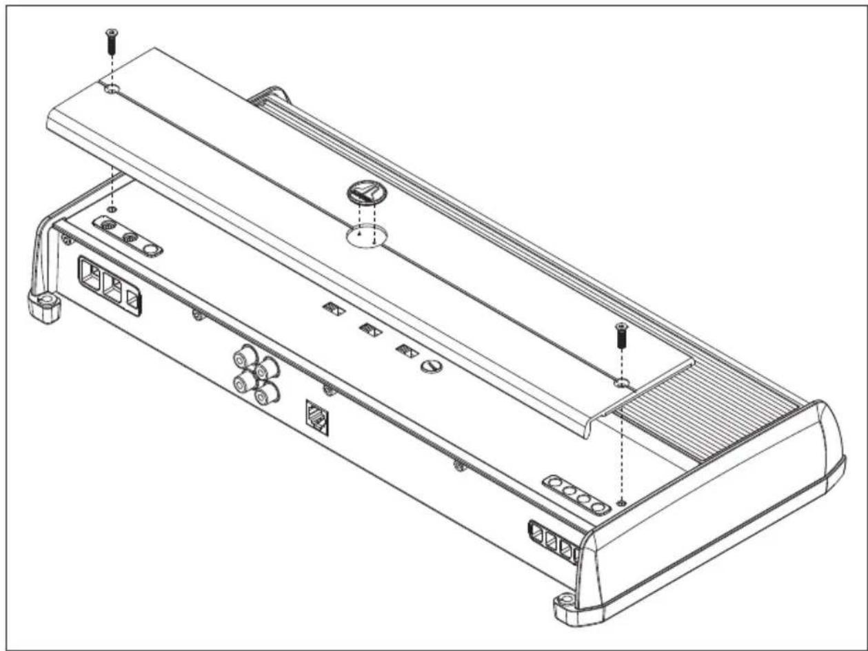
- Mount this product securely to prevent damage or injury in severe conditions.
- An appropriate fuse (or circuit breaker) at the main power wire is vital for vehicle/vessel safety and must be installed within 18 inches (45cm) of the positive battery connection.
- For ABYC and NMEA applications, circuit protection is required within 7 inches (18 cm) of the battery, unless the cable is in an enclosure or conduit.
- Listen to your audio system at levels appropriate for operating conditions and hearing safety.

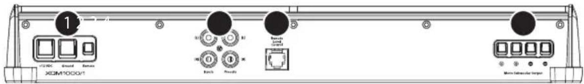
| Connection Description Notes | ||||
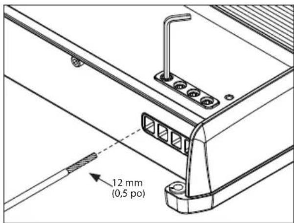
| 1 | +12 VDC Positive (+12V) Power Connection | ·4 AWG wire (required) ·Install 80A fuse at (+) battery post | ||
| Ground Negative (GND) Ground Connection · 4 AWG wire (required) | ||||
| Remote Positive (+12V) Activation Connection | ·18-12 AWG wire capacity ·See turn On Mode for more info | |||
| 2 | CH.1 Input Left Input Signal, Black RCA | ·Accepts 200mV - 4V input voltage ·If only one subwoofer channel signal is available, a Y-adaptor is recommended to feed both inputs. | ||
| CH.2 Input Right Input Signal, Red RCA | ||||
| Preout 1 Left Pass-Through Preamp Signal, Black RCA | ·Same signal that is connected to CH.1&2 inputs ·Unaffected by the amplifier's LP filter | |||
| Preout 2 Right Pass-Through Preamp Signal, Red RCA | ||||
| 3 | Remote Level Control | Remote Level Controller Connection (optional) (HD-RLC or MHD-RLC) | ·Operates as an attenuator only: Fully counter-clockwise = Level Muted Fully clockwise = Level Unaffected ·Multiple amplifiers can be controlled from a single HD-RLC using a non-duplex phone line splitter and multiple phone cables. | |
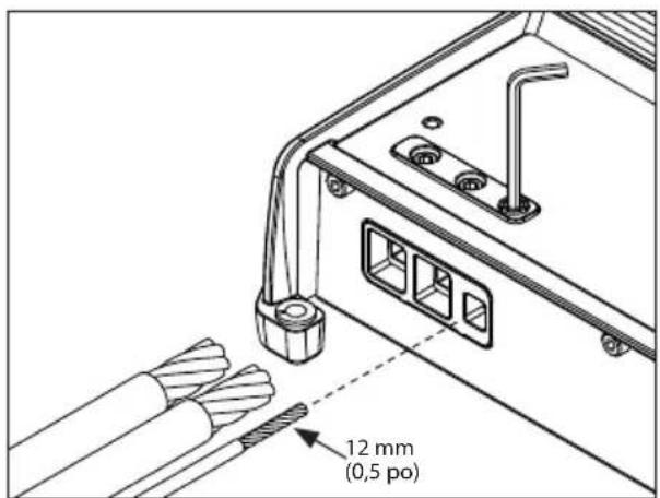
| 4 | Mono Subwoofer Output | ⊕ | (+) Positive Subwoofer Output | ·Both positive (+) connections are connected in parallel internally ·Both negative (-) connections are connected in parallel internally ·Minimum impedance load: ≥2 ohms ·16-8 AWG wire capacity |
| ⊕ | (+) Positive Subwoofer Output | |||
| ⊕ | (-) Negative Subwoofer Output | |||
| ⊕ | (-) Negative Subwoofer Output | |||
2
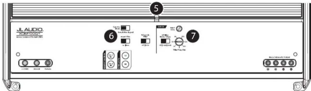
| Control (Function) Setting Description | ||||
| 5 | Status LED (indicates operating status) | Flashing Green | Amplifier Powering Up, Audio Output Muted | |
| Green On | Normal Operation, Active Audio Output | |||
| Red | On-Safe Mode, Over-Temperature Condition, Audio Output Reduced • Reverts to normal operation when temperature returns to a safe level | |||
| Amber (yellow) | On-Safe Mode, Over-Current Condition, Audio Output Muted • May exhibit repetitive, audible ticking or thumping noise in the output • Inspect for speaker/wire short circuit or low impedance | |||
| LEDs Off | Amplifier Turns Off (unexpectedly), Low-Voltage Condition • Occurs when battery or remote turn-on voltage drops below 10V • Reverts to normal operation when voltage rises above 11V | |||
| 6 | Turn On Mode (configures activation method) | Remote | +12V Remote Turn-On (Preferred) • Controlled by a switched +12V circuit or turn-on output of your source unit/OEM interface | |
| Offset | DC Offset-Sensing (Automatic) • Turns On by detecting the presence of small DC signal in OEM audio outputs and turns Off after the signal is removed | • Designed for high-level (speaker) signals only • Detects input signal from CH. 1 (L) only • Using DC Offset or Signal Sensing methods will turn the "Remote" terminal into a +12V turn-on output. | ||
| Signal | Signal-Sensing (Automatic) • Turns On by detecting full-range OEM audio signals and turns OFF after the signal is removed (within 30 seconds) | |||
| Input Filter (configures input filter application) | Car Select | for most installations (automotive or marine) | ||
| Boat Select | if experiencing interference from high-current mechanical switches/devices | |||
| Infrasonic Filter (configures high-pass filter) | Off Filtrate | defeated • Designed to conserve amplifier | power and protect subwoofer systems, without audiably degrading sub-bass output | |
| 30 Hz | Attenuates frequencies below 30 Hz, at a rate of 24dB/octave | |||
| 7 | Input Sens. educts the input stage) | Variable | Use to match the source unit's output voltage with the amplifier's inputs. See Appendix A for detailed information. | |
| LP Filter Mode/Slope (configures the low-pass filter and slope) | Off Filtrate | defeated; passes full range of frequencies present at the inputs | ||
| 12dB Attenuates frequencies above the "Filter Freq. (Hz)" dial, at a rate of 12dB/octave | ||||
| 24dB Attenuates frequencies above the "Filter Freq. (Hz)" dial, at a rate of 24dB/octave | ||||
| Filter Freq. (Hz) educts the low-pass filter cutoff frequency) | Variable | Use to adjust the cutoff frequency of the low-pass active filter, from 50 Hz - 500 Hz / 12dB per octave | ||
APPENDIX A:
Input Sensitivity Level Setting
Follow the steps below to adjust the input sensitivity of each amplifier channel pair to achieve overall system balance.
| Necessary Equipment |
| ·Digital AC Voltmeter ·Sine-wave test tone recorded at 0 dBfs reference level in the frequency range to be amplified. Do not use attenuated test tones (-10 dB, -20 dB, etc.). Full range channel/amplifier applications: 1 kHz Subwoofer channel/amplifier applications: 50 Hz ·Depending on your type of source unit, the sine-wave may be played via a CD, USB thumb drive, portable media player or Bluetooth® audio source. Make sure to disable any EQ/DSP modes on your portable media player during level setting. |
| The Nine-Step Procedure |
| 1. Disconnect the speaker(s) from the amplifier's speaker output connectors. |
| 2. Turn off all processing (bass/treble, loudness, EQ, etc.) on the source unit, processors (if used) and amplifier. Set the fader control to center position and the subwoofer level control to 3/4 of maximum, if used. |
| 3. Turn the "Input Sens." control all the way down. |
| 4. Set the source unit volume to 3/4 of full volume. This will allow for reasonable gain overlap with moderate clipping at full volume. |
| 5. Using the chart below, determine the target voltage for input sensitivity adjustment according to the nominal impedance of the speaker system connected to the amplifier outputs. |
| 6. Verify that you have disconnected the speakers before proceeding. Play a track with an appropriate sine wave (within the frequency range to be amplified) at 3/4 source unit volume. |
| 7. Connect the AC voltmeter to the speaker output terminals of the amplifier. Make sure to test the voltage at the correct terminals (+ and -). |
| 8. Increase the "Input Sens." control until the target voltage is observed with the voltmeter. |
| 9. Once you have adjusted each channel section to its maximum low-distortion output level, reconnect the speaker(s). The "Input Sens." controls can now be adjusted downward if the amplifier requires attenuation to achieve the desired system balance. |
| IMPORTANT! |
| ·Do not increase any "Input Sens." setting for any amplifier channel or channel pair in the system beyond the maximum level established during this procedure. Doing so will result in audible distortion and possible speaker damage. |
| ·It will be necessary to re-adjust the "Input Sens." if any equalizer boost is activated after setting the "Input Sens." with this procedure. This applies to any EQ boost circuit, including source unit tone controls or EQ circuits. EQ cuts will not require re-adjustment. |
| Nominal Impedance Target AC Voltage | |
| 4Ω 49.0 V | |
| 3Ω 49.0 V | |
| 2Ω 44.7 V | |
| 1Ω not recommended | |
SPECIFICATIONS
| Amplifier Section | |||
| Amplifier Topology | NexD™ Ultra-High Speed Class D | ||
| Power Supply Type | Unregulated MOSFET Switching | ||
| Minimum Copper Power/GND Wire | 4 AWG (Note: CCA/Copper Clad Aluminum wire is not recommended.) | ||
| Recommended Fuse 80 A | |||
| Rated RMS Power @ 14.4V, <1% THD+N | 600W x 1 @ 4 Ω 800W | x 1 @ 3 Ω 1000W x 1@ 2 Ω | |
| Rated RMS Power @ 12.5V, <1% THD+N | 500W x 1 @ 4 Ω 650W | x 1 @ 3 Ω 800W x 1@ 2 Ω | |
| Frequency Response | 7 Hz - 500 Hz (+0, -1dB) | ||
| S/N Ratio (A-weighted, 20 Hz-20 kHz noise bandwidth) | >83 dB (Referred to rated power), >53 dB (Referred to 1 W) | ||
| Damping Factor | >1000 / 50 Hz @ 4 Ω, >500 / 50 Hz @ 2 Ω | ||
| Input Section | |||
| Number of Inputs 2 | (One Stereo Pair) | ||
| Input Type | Differential-Balanced with RCA jack inputs | ||
| Input Voltage Range | 200mV - 4V RMS | ||
| Signal Processing | |||
| Filter Type | Active, 12dB or 24dB/octave Low-Pass, (50 - 500 Hz), defeatable | ||
| Remote Level Control | HD-RLC or MHD-RLC (optional). Full mute to 0 dB range. | ||
| Dimensions | |||
| L x W x H | 14.73 in. x 7.09 in. x 2.05 in. (374 mm x 180 mm x 52 mm) | ||

Due to ongoing product development, all specifications are subject to change without notice.