
ELVOX ESM3.1 - Electronic board Vimar - Free user manual and instructions
Find the device manual for free ELVOX ESM3.1 Vimar in PDF.
| Product type | Control unit for sliding gate gearmotors |
| Brand | Vimar |
| Model | ELVOX ESM3.1 |
| Power supply | 230 VAC 50 Hz / 120 VAC 50/60 Hz |
| Maximum motor power | 800 W |
| Duty cycle | 30 % |
| Operating temperature | -10 °C to +55 °C |
| Built-in radio receiver | 433 MHz, capacity 250 remote controls (fixed or rolling code) |
| Accessories power supply | 24 VDC, 300 mA max |
| Flashing light output | 230/120 VAC, 25 W max |
| Open gate indicator output | 24 VDC, 2 W max |
| Limit switch inputs | Yes (LSC and LSO) |
| Encoder input | Yes (for obstacle detection and speed control) |
| Main functions | Customizable slowdown, obstacle detection, LED diagnostics, programming of travel and remote controls |
| Safety | Installation by qualified technician, surge protection, mandatory disconnecting switch |
| Maintenance and cleaning | Disconnect power before any operation; use only original spare parts |
| Spare parts and repairability | Repair by qualified technician with original parts |
| General information | Multilingual manual, declaration of conformity available at www.vimar.com |
Frequently Asked Questions - ELVOX ESM3.1 Vimar
User questions about ELVOX ESM3.1 Vimar
0 question about this device. Answer the ones you know or ask your own.
Ask a new question about this device
Download the instructions for your Electronic board in PDF format for free! Find your manual ELVOX ESM3.1 - Vimar and take your electronic device back in hand. On this page are published all the documents necessary for the use of your device. ELVOX ESM3.1 by Vimar.
USER MANUAL ELVOX ESM3.1 Vimar
natural_image
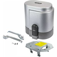
Electronic circuit board with integrated components and connectors (no visible text or symbols)SL230.T - SL230.T.120
230/120 VAC DIP control board for sliding gates
natural_image
Technical line drawing of an electrical contactor or transformer assembly (no text or symbols visible)- Product characteristics .... 14
- Technical data....15
- Preparing the wiring....15
- Electrical connections 15
- Control unit description....16
- Electrical wiring....17
- Description of the LEDs in the circuit....22
- Buttons in the circuit 22
- Preliminary check 22
- Programming and deleting the remote control....22
- Programming 23
- Testing the automatic gate system 24
- Trimmer for adjustments....24
- Dip switch functions 25
- Troubleshooting....25
Declaration of conformity....25
The following safety information is an integral and essential part of the product and must be supplied to the user.
Read it carefully as it provides important guidelines regarding installation, use and maintenance. Always store this module carefully and transfer it to any subsequent users of the system. Incorrect installation or improper use of the product may constitute a serious hazard.
IMPORTANT - SAFETY INFORMATION
Installation must be performed by professionally qualified personnel in observance of current national and European legislation.
After removing the packaging check the condition of the device. If in doubt, consult a qualified technician.
Packaging materials (carton, plastic bags, staples, polystyrene, etc.) must be disposed of in suitable containers and must not be dispersed into the environment. Above all they must be kept out of the reach of children.
The installation, electrical connections and settings must be executed in accordance with sound engineering practice. Make certain that the data on the data plate conform with the mains electrical supply data and make certain that the section of the connection cables is suitable for the loads applied. Do not install the product in environments where there is a risk of explosion or which are disturbed by electromagnetic fields. The presence of flammable gases or fumes constitutes a serious hazard.
Equip the mains supply with an overvoltage protection device, a 1-way switch/disconnector and/or an RCD suited for the product and in conformity with the standards in force.
Clearly indicate with an appropriate sign on the gate, rolling door, window or barrier that they are remotely operated.
VIMAR s.p.a. denies all liability for damage incurred when devices and/or components are used that are incompatible in terms of product integrity, safety and operation.
This equipment must be used exclusively as specified in design; any other use is to be considered improper and therefore hazardous. Always disconnect the equipment from the power supply by means of the main switch or by removing the plug before performing maintenance or cleaning. Use exclusively genuine spare parts for repairs and replacements.
The installer must provide all information regarding operation, maintenance and use of the single parts and the system as a whole.
1. Product characteristics.
Control unit for governing 230/120 VAC sliding gate gear motors with 800W max power, equipped with inputs for limit switch, encoder (used for obstacle detection and speed control) and integrated 433 Mhz receiver.
The control unit is:
- designed to customise the space and speed of deceleration in both opening and closing phases.
- equipped with an obstacle detection system (if there is an encoder circuit)
- designed for input diagnostics via LED
- fitted with an integrated receiver with capacity for 250 remote control codes (hard coded or rolling code)
2. Technical data.
| Control panel SL230.T / SL230.T.120 | |
| Power supply 230 VAC 50 Hz - 120 VAC 50/60 Hz | |
| Type of use Residential and apartment blocks | |
| Frequency of use 30% | |
| Operating temperature -10°C / +55°C | |
| Accessories power supply 24 V DC - 300 mA max | |
| Flashing light output 230/120 VAC - 25 W max | |
| Gate open warning light output 24 VDC 2W max | |
| Protection fuse for 230VAC line Quick-acting fuse F5 A | |
| Protection fuse for 120VAC line Quick-acting fuse F6.3 A |
3. Preparing the wiring.
Key:
A - Sliding actuator
B - Rack
C - External photocell
D - Internal photocell
E - Photocell column
F - Flashing lamp
G - Keyswitch
4. Electrical connections.
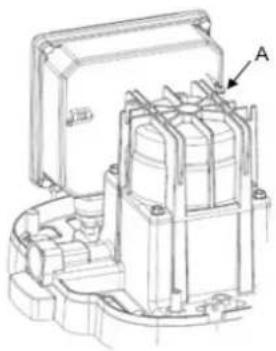
Draw out the power supply cable for a length of approx. 20 cm. Strip the earth wire conductor.
Crimp the free eyelet screwed to the earth connection socket on the gear motor casting (Ref. A in the figure); for easier crimping you can also remove the eyelet from the socket making sure you reconnect the pre-wired earth between the control unit and the gear motor correctly.
Strip the live and neutral wires and connect them to the control unit as indicated in the manual.
natural_image
Technical line drawing of an electrical contactor or transformer housing (no text or symbols visible)5. Control unit description.
Control unit for governing gear motors for sliding gates at 230/120 VAC equipped with inputs for built-in receiver limit switch. The control unit is:
- designed to customise the space and speed of deceleration in both opening and closing phases.
- equipped with an obstacle detection system (if there is an encoder circuit)
- designed for input diagnostics via LED
- fitted with an integrated receiver with capacity for 250 remote control codes (hard coded or rolling code)
Key:
- Removable terminal for 24 VDC outputs, for safety devices and control inputs
- Removable terminal for the power supply line, flashing lamp and 230 VAC electric motor
- Fixed antenna terminal
- LED for input diagnostics
- LED for programming diagnostics
- Push buttons for programming the travel and remote controls
- Trimmer for adjustments
- Dip switch for programming functions
- Protection fuse for the motor output, transformer and flashing lamp (230V F5A quick-acting, 120V F6.3 A quick-acting)
- Encoder Connector (only for motor models with Encoder)
CAUTION:
Secure the cables on the actuator with cable ties, to avoid them becoming loose and creating hazardous situations. In addition, secure the cables of the M2 power terminal block with cable ties separately from the cables of the M1 signal terminal block.
6. Electrical wiring.
Description of terminals:
| Terminal block M1 | ||
| Terminal number Board marking Description | ||
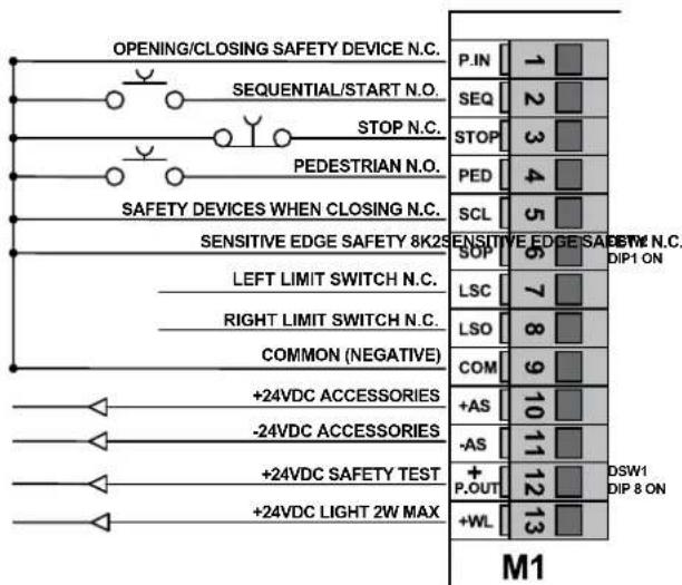
| 1 | P.IN | Input (N.C.) for opening and closing safety devices (momentary stop) |
| 2 SEQ Push button (N.O.) for opening and closing (sequential or start) | ||
| 3 STOP Push button (N.C.) for stop | ||
| 4 PED Push button (N.O.) for pedestrian opening | ||
| 5 SCL Input (N.C.) for closing safety devices (reopening) | ||
| 6 | SOP | Programmable input for non resistive (N.C.) or resistive 8K2 sensitive edge |
| 7 | LSC | Input (N.C.) for left limit switch (activated with right-hand cam) |
| 8 | LSO | Input (N.C.) for right limit switch (activated with left-hand cam) |
| 9 COM Common inputs and indicator light (negative) | ||
| 10 | +AS | Positive for 24 VDC accessories power supply |
| 11 -AS | Negative for 24 VDC accessories power supply | |
| 12 | +P.OUT | 24VDC positive programmable output for safety test or 2^nd radio channel |
| 13 | +WL Positive for indicator light 24V, 2W max | |
| Terminal block M2 | ||
| 14 | MOP Motor opening direction output | |
| 15 MCL Motor closing direction output | ||
| 16 | MCOM | Common motor winding output |
| 17 | FL | Flashing lamp 230/120 V 50 Hz 25 W max (NEUTRAL) |
| 18 | FL | Flashing lamp 230/120 V 50 Hz 25 W max (PHASE) |
| 19 | N | Input for 230/120 V 50 Hz line (NEUTRAL) |
| 20 | L | Input for 230/120 V 50 Hz line (PHASE) |
| 21 | Input for earth connection | |
| The sum of the absorptions of the 24VDC accessories must not exceed 300 mA | ||
Wiring for power supply line, flashing lamp and electric motor:
Input wiring.
The control unit is supplied with non-jumpered normally closed safety inputs (P.IN, STOP, SCL, SOP).
Add a jumper between the common (COM) and the input you do not intend to use. LEDs DL1 DL3 DL5 and DL6 must be on.
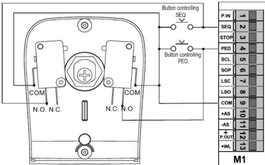
Connecting control push buttons and keyswitch.
The contacts are normally open. Input SEQ (LED DL2) controls the opening or complete closing of the gate. Input PED (LED DL4) controls the opening or partial closing of the gate. LEDs DL2 or DL4 and LED DL.S light up when the keyswitch or push buttons connected in parallel are operated.
Connecting a timer or magnetic induction detector.
The contact is normally open. With DSW1 Dip switch 1 ON (automatic closing active) and DSW1 Dip switch 4 ON (collective function active), you can connect a timer or a magnetic induction detector. Normally open input P.SEQ, if closed, operates the complete opening of the gate for as long as the contact remains closed. The gate opens and remains open. Controls SEQ, PED and the remote controls stored are not active until the contact is reopened. This input is used to open the gate and keep it open at the busiest hours. LED DL2 lights up and LED DL.S flashes when the timer or the magnetic induction detector are operated.
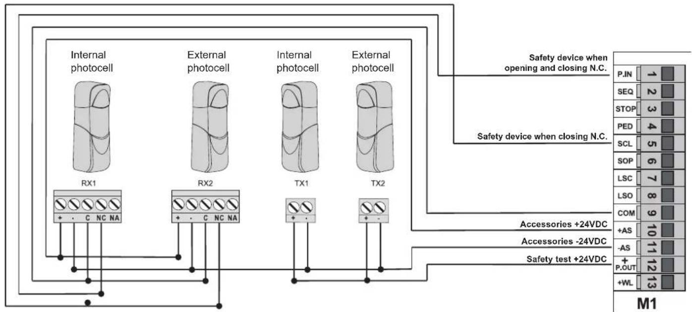
Connecting photocells.
Observe the correct polarity for the photocell power supply. Contacts SCL and P.IN are normally closed.
The triggering of input SCL, during gate closing, inverts motion. If not used, jumper between COM and SCL. With the photocells not engaged, LED DL5 must be on.
The triggering of input P.IN, during gate closing, blocks motion until the photocells remain engaged; upon their disengagement, motion is inverted into an opening of the gate. The triggering of input P.IN, during gate opening, blocks motion until the photocells remain engaged; upon their disengagement, gate opening resumes. If not used, jumper between COM and P.IN. With the photocells not engaged, LED DL1 must be on.
flowchart
graph TD
    A["Internal photocell"] --> B["RX1"]
    C["External photocell"] --> D["RX2"]
    E["Internal photocell"] --> F["TX1"]
    G["External photocell"] --> H["TX2"]
    B --> I["+ - C NC NA"]
    D --> J["+ - C NC NA"]
    F --> K["+ -"]
    H --> L["+ -"]
    I --> M["M1"]
    J --> M
    K --> M
    L --> M
    M --> N["P.IN 1"]
    M --> O["SEQ 2"]
    M --> P["STOP 3"]
    M --> Q["PED 4"]
    M --> R["SCL 5"]
    M --> S["SOP 6"]
    M --> T["LSC 7"]
    M --> U["LSO 8"]
    M --> V["COM 9"]
    M --> W["+AS 10"]
    M --> X["-AS 11"]
    M --> Y["P.OUT 12"]
    M --> Z["+WL 13"]
    style A fill:#f9f,stroke:#333
    style C fill:#f9f,stroke:#333
    style E fill:#f9f,stroke:#333
    style G fill:#f9f,stroke:#333
    style B fill:#ccf,stroke:#333
    style D fill:#ccf,stroke:#333
    style F fill:#ccf,stroke:#333
    style H fill:#ccf,stroke:#333
    style K fill:#ccf,stroke:#333
    style L fill:#ccf,stroke:#333
    style J fill:#ccf,stroke:#333
    style K fill:#ccf,stroke:#333
    style L fill:#ccf,stroke:#333
    style M fill:#ccf,stroke:#333
    style N fill:#cfc,stroke:#333
    style O fill:#cfc,stroke:#333
    style P fill:#cfc,stroke:#333
    style Q fill:#cfc,stroke:#333
    style R fill:#cfc,stroke:#333
    style S fill:#cfc,stroke:#333
    style T fill:#cfc,stroke:#333
    style U fill:#cfc,stroke:#333
    style V fill:#cfc,stroke:#333
    style W fill:#cfc,stroke:#333
    style X fill:#cfc,stroke:#333
    style Y fill:#cfc,stroke:#333
    style Z fill:#cfc,stroke:#333
Connecting sensitive edge and/or internal photocells.
With DSW2 Dip switch 1 OFF, programmable input SOP is configured as normally closed for the use of a non-resistive sensitive edge N.C. With the sensitive edge not engaged LED DL6 must be on. If not used, jumper between COM and SOP.
With DSW2 Dip switch 1 ON, programmable input SOP is configured for the use of a resistive sensitive edge 8K2. With the sensitive edge not engaged LED DL6 must be on. If not used, set DSW2 Dip switch 1 to OFF and jumper between terminal COM and SOP.
The triggering of input SOP, during closing, inverts and immediately stops motion. After the edge is disengaged, the gate remains still until a new control is given. The triggering of input SOP, during opening, inverts and immediately stops motion. After the edge is disengaged, gate closing motion resumes.
Electrical connection with Photo-test function active
With DSW1 Dip switch 8 ON, programmable input P.OUT controls the operation of the safety devices.
flowchart
graph TD
    A["Internal photocell"] --> B["RX1"]
    C["External photocell"] --> D["RX2"]
    E["Internal photocell"] --> F["TX1"]
    G["External photocell"] --> H["TX2"]
    I["Safety device when opening and closing N.C."] --> J["P.IN 1"]
    K["Safety device when closing N.C."] --> L["SEQ 2"]
    M["Safety device when closing N.C."] --> N["STOP 3"]
    O["Safety device when closing N.C."] --> P["PED 4"]
    Q["Safety device when closing N.C."] --> R["SCL 5"]
    S["Safety device when closing N.C."] --> T["SOP 6"]
    U["LSC 7"] --> V["LSC 7"]
    W["LSO 8"] --> X["LSO 8"]
    Y["COM 9"] --> Z["COM 9"]
    AA["+AS 10"] --> AB["+AS 10"]
    AC["-AS 11"] --> AD["-AS 11"]
    AE["+P.OUT 12"] --> AF["+P.OUT 12"]
    AG["+WL 13"] --> AH["+WL 13"]
    AI["Accessories +24VDC"] --> AJ["Accessories -24VDC"]
    AK["Safety test +24VDC"] --> AL["Safety test +24VDC"]
    style A fill:#f9f,stroke:#333
    style C fill:#f9f,stroke:#333
    style E fill:#f9f,stroke:#333
    style G fill:#f9f,stroke:#333
    style I fill:#ccf,stroke:#333
    style K fill:#ccf,stroke:#333
    style M fill:#ccf,stroke:#333
    style Q fill:#ccf,stroke:#333
    style S fill:#ccf,stroke:#333
    style U fill:#ccf,stroke:#333
    style X fill:#ccf,stroke:#333
    style Y fill:#ccf,stroke:#333
    style Z fill:#ccf,stroke:#333
    style AA fill:#ccf,stroke:#333
    style AB fill:#ccf,stroke:#333
    style AC fill:#ccf,stroke:#333
    style AD fill:#ccf,stroke:#333
    style AE fill:#ccf,stroke:#333
    style AF fill:#ccf,stroke:#333
    style AH fill:#ccf,stroke:#333
Stop push button connection.
Input STOP is normally closed. The opening of the contact causes the gate to stop and the automatic closing time to be suspended. If not used jumper between COM and STOP. With the push button not engaged, LED DL3 must be on.
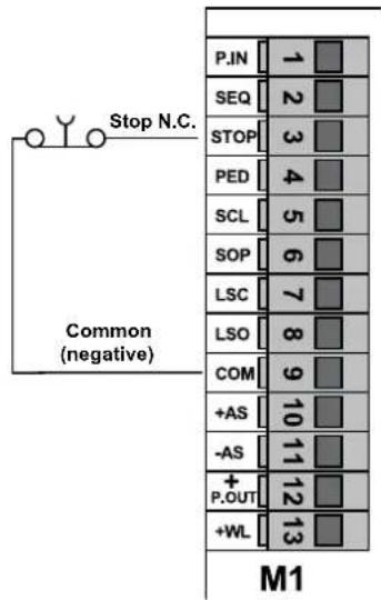
N.B.: if there are no photocells, sensitive edges or stop push buttons in the system, inputs P.IN, STOP, SCL, SOP must be jumpered with COM and DSW1 Dip switch 8 DSW2 Dip switch 1 must be set to OFF.
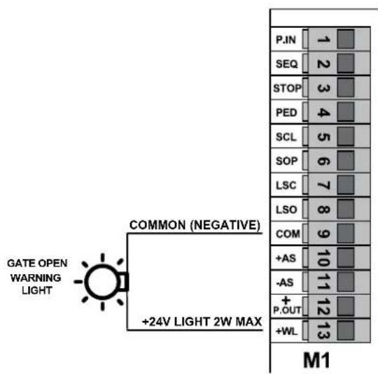
Connecting the Gate Open Warning Light.
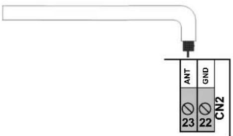
Antenna connection:
a 17 cm rigid wire is supplied, which acts as an antenna and should be wired to terminal ANT.
7. Description of the LEDs in the circuit.
| Abbreviation | Description |
| DL1 Displays the | status of input P.IN (terminal number 1).If not engaged, the LED remains on.Used for opening and closing safety devices, otherwise jumper between terminal COM and P.IN |
| DL2 Displays the | status of input SEQ (terminal number 2).If not engaged, the LED remains off.Used to control the sequential opening (opens, stops, closes, stop) or start (opens, closes). |
| DL3 Displays the | status of input STOP (terminal number 3).If not engaged, the LED remains on.Used to control the gate stopping devices, otherwise jumper between terminal COM and STOP |
| DL4 Displays the | status of input PED (terminal number 4).If not engaged, the LED remains off.Used to control the partial opening of the gate (pedestrian) |
| DL5 Displays the | status of input SCL (terminal number 5).If not engaged, the LED remains on.Used for closing safety devices, otherwise jumper between terminal COM and SCL. |
| DL6 Displays the | status of input SOP (terminal number 6).Using the non resistive sensitive edge with DSW2 Dip switch 1 set to OFF, if not engaged, the LED remains on, otherwise jumper between terminal COM and SOP.Using the 8K2 resistive sensitive edge with DSW2 Dip switch 1 set to ON, if not engaged, the LED remains on, otherwise set DSW2 Dip Switch 1 to OFF and jumper between terminal COM and SOP. |
| DL7 Displays the | status of input LSC left limit switch (terminal number 7).If not engaged, the LED remains on |
| DL8 Displays the | status of input LSO right limit switch (terminal number 8).If not engaged, the LED remains on |
| DL.S Displays the | programming and test status.If not engaged, the LED remains off. |
8. Push buttons in the circuit.
| Abbreviation | Description |
| P1 Travel learning push button | |
| P2 Remote controls learning push button | |
9. Preliminary check.
After powering up the control unit the DL.S LED comes on for a second.
Check the input diagnostics LEDs DL1, DL3, DL5, DL6, DL7 and DL8 are on.
If one of the normally closed contacts or one of the normally open contacts is not in the rest status, the limit switch learning operation cannot be carried out and the DL.S LED flashes quickly to indicate a possible fault.
Should one of the safety inputs P.in, STOP, SCL, SOP not be used, insert a jumper between COM and the input not being used.
10. Programming and deleting the remote control.
The maximum storage capacity is 250 rolling code remote control codes.
Caution: The remote controls can only be saved and deleted when the gate is stationary.
Programming the button of the remote control associated with input SEQ.
- Press push button P2 and hold it down until LED DL.S (PRG) starts to flash ( 1^st flashing frequency).
- Release push button P2.
- Within 10 seconds, activate the remote control button to be learnt and associated with the sequential or start control.
- Learning procedure completion will be signalled by the flashing of the flashing lamp, followed by the LED DLS that stops flashing.
- Repeat the process for every remote control to be learnt.
Programming the button of the remote control associated with input PED for use as 2^nd channel when DSW1 Dip switch 8 is ON. Programming the button of the remote control associated with input P.OUT for use as 2^nd channel when DSW1 Dip switch 8 is OFF.
- Press push button P2 and hold it down. LED DL.S starts to flash ( 1^st flashing frequency).
- Do not release push button P2 until it flashes faster ( 2^nd flashing frequency).
- Release push button P2.
- Within 10 seconds, activate the remote control button to be learnt and associated with the pedestrian control.
- Learning procedure completion will be signalled by the flashing of the flashing lamp, followed by the LED DL.S that stops flashing.
- Repeat the process for every remote control to be learnt.
Deleting a single button saved on the remote control.
- Press push button P2 and hold it down. LED DL.S starts to flash ( 1^st flashing frequency).
- Do not release push button P2. The flashing becomes faster ( 2^nd flashing sequence).
- Do not release push button P2 until it flashes faster ( 3^nd flashing frequency).
- Release push button P2.
- Within 10 seconds, activate the button of the remote control to be deleted.
- Deletion procedure completion will be signalled by the flashing of the flashing lamp, followed by the LED DL.S that stops flashing.
Deleting all the saved remote controls.
- Disconnect the power supply to the control unit.
- Reconnect the power supply to the control unit by holding down push button P2.
- Wait for the DL.S LED to stop flashing.
- At the end of this procedure, all the remote controls in memory are deleted.
11. Programming.
Before you begin programming, we recommend you save at least one remote control associated with input SEQ.
Manual tuning procedure to position the gate.
In order to perform the gate positioning manoeuvres before you begin any learning or checks, there is a function designed to move the motor, both opening and closing, in dead-man mode.
To enter this mode, press both push buttons P1 and P2 simultaneously, then LED DL.S lights up permanently to indicate dead-man tuning mode.
Release the buttons.
Push button P1 now controls opening while push button P2 controls closing, or vice-versa depending on the position of DSW1 Dip switch7.
Simply hold down one of the two push buttons to move the gate.
Exit dead-man mode by pressing both push buttons P1 and P2 simultaneously.
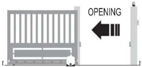
Selecting the direction of opening.
The control unit is equipped with dip switches to select the direction of gate opening.
If the gate opens towards the right, set DSW1 Dip switch 7 to OFF and switch off the power supply to the control unit and then back on again.
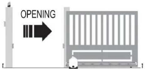
If the gate opens towards the left, set DSW1 Dip switch 7 to ON and switch off the power supply to the control unit and then back on again.
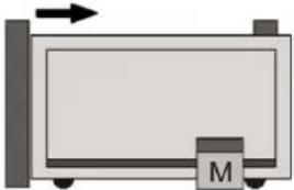
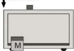
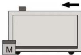
Procedure for gate travel programming:
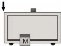
- Begin the procedure with the gate closed.
- Press push button P1 and hold it down until LED DL.S starts to flash.
- Release push button P1.
- Follow the programming phases shown in the figure.
- Programming ends when LED DL.S stops flashing.
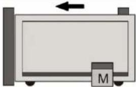
 | 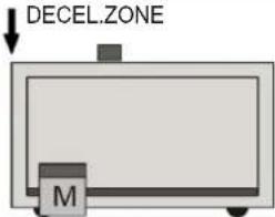 | 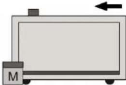 | ||
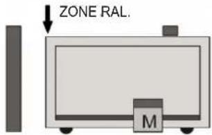
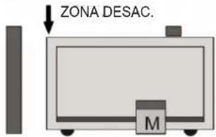
| 1st STARTCAUTION!START WITH THE GATE CLOSED.THE FIRST START STARTS THELEARNING BY MOVING THEMOTOR IN OPENING. | 2nd STARTTHE SECOND START SETS THESTARTING POINT OF OPENINGDECELERATION. | ONCE IT REACHES THE OPENING LIMITSWITCH, THE GATE RESUMES CLOSING. | ||
| DECEL.ZONE | 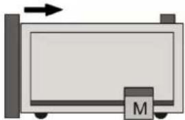 | 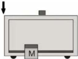 | ||
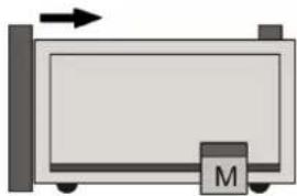
| 3rd STARTTHE THIRD START SETS THESTARTING POINT OF CLOSINGDECELERATION. | ONCE IT REACHES THE CLOSING LIMITSWITCH, THE GATE RESUMESOPENING. | 4th STARTTHE FOURTH START SETS THEPARTIAL OPENING POINT(PEDESTRIAN) | ||
 | ONCE PARTIAL OPENING IS FIXED, THE GATE RESUMES CLOSING.COMPLETE CLOSING AND THE DL.S LED TURNING OFF INDICATE THE END OF PROGRAMMING | |||
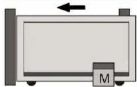
1st START
CAUTION!
START WITH THE GATE CLOSED.
THE FIRST START STARTS THE
LEARNING BY MOVING THE
MOTOR IN OPENING.
THE SECOND START SETS THE STARTING POINT OF OPENING DECELERATION.
THE THIRD START SETS THE STARTING POINT OF CLOSING DECELERATION.
ONCE IT REACHES THE CLOSING LIMIT SWITCH, THE GATE RESUMES OPENING.
THE FOURTH START SETS THE
PARTIAL OPENING POINT
(PEDESTRIAN)
2nd START
3rd START
4th START
If the gate movement turns out to be reversed, check the DSW1 dip switch 7, do not change the wiring of either the limit switch or the electric motor.
12. Testing the automatic gate system.
It is necessary to test all the accessories connected to the control unit, especially the safety devices such as the sensitive edges and photocells. Remember that the photocells reverse the movement of the gate only during closing and the sensitive edges and/or internal photocells, if engaged during opening, reverse the movement of the gate for 1.5 seconds, while if engaged when closing they fully re-open the gate.
13. Trimmer for adjustments
| Trimmer Function Description Range | |||
| TR1-DELAY Pause time | With DSW1 Dip switch 1 ON, it adjusts the amount of time during which the gate remains stationary before automatic closing. | From 1 to 140 seconds, maximum, clockwise | |
| TR2-TORQ Motor torque It adjusts the elec | ectromechanical motor. | From 20 to 100%, maximum, clockwise | |
| TR3-BRK Braking intensity It adjusts the br | braking intensity of the motor during stopping phases. | From 0 to 100%, maximum, clockwise | |
| TR4-SL Slowdown speed | It adjusts the deceleration speed.If turned completely clockwise, deceleration is excluded | From 30 to 80%, maximum, anti-clockwise | |
| TR5-SENSE | Obstacle sensitivity(only with Encoder) | Function only available for motor models with Encoder. It adjust the impact sensitivity. | From 100 to 10%, maximum, clockwise |
14. Dip switch functions.
| Number Status | Function | Description | ||
| DSW1 | DIP 1 | OFF Automatic closing disabled - | ||
| ON Automatic closing enabled The open gate is closed automatically after the pause time. | ||||
| DIP 2 | OFF Operating logic: Opens-Stops-Closes-Stops | It modifies the operating sequence of inputs SEQ (sequential) and PED (pedestrian) also via remote control. | ||
| ON Operating logic: Opens-Closes | ||||
| DIP 3 | OFF Courtesy function on photocell disabled - | |||
| ON | Courtesy function on photocell enabled | Reduction to 3sec of the residual pause time after passing over photocells. | ||
| DIP 4 | OFF Collective operating logic disabled - | |||
| ON | Collective operating logic enabled | When opening the gate, it ignores any controls and reloads the pause time when on pause | ||
| DIP 5 | OFF Pre-flashing disabled - | |||
| ON | Pre-flashing enabled | The flashing lamp starts flashing 3 seconds before the start of each movement | ||
| DIP 6 | OFF | Flashing built into the flashing lamp. | It configures the output for flashing lamps with independent flashing. | |
| ON | Flashing controlled by the control unit. | It configures the output for flashing lamps without independent flashing. | ||
| DIP 7 | OFF | Gate opens towards the Right | Configures gate opening towards the right | |
| ON | Gate opens towards the Left | Configures gate opening towards the left | ||
| DIP 8 | OFF P.OUT 2 ^nd remote control channel | Input P.OUT works as 2^nd radio channel | ||
| ON | P.OUT Safety test (Photo-test) | Input P.OUT controls the operation of the safety devices | ||
| DSW2 | DIP 1 | OFF | Non-resistive edge SOP | SOP input configured to connect a non-resistive sensitive edge. |
| ON | 8K2 resistive edge SOP | SOP input configured to connect an 8K2 resistive sensitive edge. | ||
| DIP 2 | OFF Soft Start disabled | The gate begins moving at constant speed | ||
| ON Soft Start enabled | The gate begins moving at a progressive speed | |||
15. Troubleshooting.
| Problem | Cause | Solution |
| The automatic gate system does not work | No mains supply | Check the power line switch |
| Blown fuses | Replace the fuses with others of the same value | |
| Control and safety inputs not working | Check the diagnostics LEDs: DL1 P.IN, DL3 STOP, DL5 SCL, DL6 SOP must be on. | |
| Safety device test failed | Check the operation of the safety devices installed if 4 simultaneous flashes of the following occur: LED DL.S, indicator light and flashing lamp. | |
| Triac operating control test failed | Replace the control unit if 2 simultaneous flashes of the following occur: LED DL.S, indicator light and flashing lamp. | |
| (Only for motor models with Encoder) Motor not working properly | (Only for motor models with Encoder) Replace the motor if 3 simultaneous flashes of the following occur: DL.S LED, indicator light and flashing lamp. | |
| The limit switches remain activated. | Check the capacitor and/or wiring of the board/motor and/or the presence of any obstacles in deceleration zones if 6 simultaneous flashes of the following occur: DL.S LED, indicator light and flashing lamp. | |
| The limit switches are not activated. | Check the fixing of the limit switch cams and/or whether you have closed the release if 7 simultaneous flashes of the following occur: LED DL.S, indicator light and flashing lamp. | |
| You cannot save the remote controls | Batteries of the remote control discharged | Replace the batteries |
| Remote control not compatible with the first one saved | The first saved rolling-code remote control configures the control unit to save only rolling-code remote controls and not hard coded remote controls. | |
| Reached memory saturation | Delete at least one remote control or add an external receiver (maximum capacity 250 rolling-code remote control codes) | |
| The remote control does not work | Batteries of the remote control discharged | Replace the batteries |
| You cannot enter travel programming | Safety devices open | Check the diagnostics LEDs: DL1 P.IN, DL3 STOP, DL5 SCL, DL6 SOP must be on. |
| As soon as the gate starts it stops and reverses | Low acceleration on starting | Increase the TR2 TORQ trimmer |
| During slowdown, the gate stops and reverses | Slowdown speed too low | Increase the TR4 SL trimmer |
| The gate stops just before the limit switch trips | The limit switch does not work properly | Advance the limit switch cam |
Declaration of Conformity.
Vimar S.p.A. declares that the device complies the following directives:
2014/53/EU (RED)
2014/30/EU (EMC)
2014/35/EU (LVD)
2006/42/EC (Machinery Directive)
The full text of the EU declaration of conformity is on the product sheet available on the following website: www.vimar.com.
REACH (EU) Regulation no. 1907/2006 – Art.33. The product may contain traces of lead.
Sommaire :
Page
natural_image
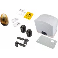
Technical line drawing of an electrical contactor or motor assembly (no text or symbols visible)5. Description de la centrale.
natural_image
Simple diagram of a rectangular container with a labeled M and directional arrow (no text or symbols beyond the label)
1er START
ATTENTION!
DÉMARRER PORTAIL FERMÉ
LE PREMIER START ENCLENCHE
L'APPRENTISSAGE EN ACTIONNANT
LE MOTEUR EN OUVERTURE.
I ZONE RAL.
natural_image
Simple diagram of a rectangular container with a labeled 'M' and an arrow pointing downward (no text or symbols beyond the label)
2e START
LE DEUXIÈME START FIXE LE POINT
DE DÉBUT DU RALENTISSEMENT
D'OUVERTURE.
natural_image
Simple line drawing of a rectangular device with a labeled base (M) and an arrow pointing to it, no text or symbols present.APRÈS AVOIR ATTEINT LE FIN DE COURSE D'OUVERTURE, LE PORTAIL REDÉMARRE POUR SE FERMER.

3e START
LE TROISIÈME START FIXE LE POINT
DE DÉBUT DU RALENTISSEMENT DE
FERMETURE.
natural_image
Simple diagram of a rectangular device with a labeled component 'M' and an arrow pointing upward (no text or symbols beyond the label)APRÈS AVOIR ATTEINT LE FIN DE COURSE DE
FERMETURE, LE PORTAIL REDÉMARRE POUR
S'OUVRIR.
natural_image
Simple diagram of a rectangular device with a downward arrow and a labeled mass 'M' (no text or symbols beyond the label)
4e START
LE QUATRIÈME START FIXE LE POINT DE
L'OUVERTURE PARTIELLE (PIÉTON)
natural_image
Simple diagram of a rectangular container with a downward arrow and a labeled mass 'M' (no text or symbols beyond the label)natural_image
Technical line drawing of an electrical transformer or inductor assembly (no text or symbols visible)natural_image
Simple diagram of a rectangular container with a labeled mass 'M' and an arrow indicating upward motion (no text or symbols beyond the label)natural_image
Simple diagram of a rectangular frame with a labeled component 'M' and an arrow pointing downward (no text or symbols beyond the label)natural_image
Simple diagram of a rectangular device with a labeled component 'M' and an arrow pointing to it (no text or symbols beyond the label)natural_image
Simple diagram of a rectangular device with a labeled component 'M' and an arrow pointing upward (no text or symbols beyond the label)natural_image
Simple diagram of a rectangular device with a downward arrow and a labeled mass 'M' (no text or symbols beyond the label)natural_image
Simple diagram of a rectangular container with a downward arrow and a labeled M (no text or symbols beyond the label)natural_image
Technical line drawing of an electrical contactor or transformer housing (no text or symbols visible)natural_image
Simple diagram of a rectangular container with a labeled mass 'M' and an arrow indicating direction (no text or symbols beyond the label)natural_image
Simple diagram of a rectangular container with a labeled 'M' and an arrow pointing downward (no text or symbols beyond the label)natural_image
Simple diagram of a rectangular device with a labeled component 'M' and an arrow indicating direction (no text or symbols beyond the label)DESPUÉS DE ALCANZAR EL FIN DE CARRERA DE APERTURA, LA CANCELA VUELVE A ARRANCAR PARA CERRAR.
natural_image
Simple diagram of a rectangular device with a labeled component 'M' and an arrow pointing upward (no text or symbols beyond the label)DESPUÉS DE ALCANZAR EL FIN DE CARRERA DE CIERRE, LA CANCELA VUELVE A ARRANCAR PARA ABRIR.

natural_image
Simple diagram of a rectangular device with a downward arrow and a labeled mass 'M' (no text or symbols beyond the label)
4° ARRANQUE
EL CUARTO ARRANQUE FIJA EL PUNTO DE APERTURA PARCIAL (PEATONAL)
natural_image
Simple diagram of a rectangular container with a downward arrow and a labeled mass 'M' (no text or symbols beyond the label)natural_image
Technical line drawing of an electrical transformer or inductor assembly (no text or symbols visible)natural_image
Simple diagram of a rectangular container with a labeled mass 'M' and an arrow indicating direction (no text or symbols beyond the label)natural_image
Simple diagram of a rectangular container with a labeled 'M' and an upward arrow, no text or symbols present.natural_image
Simple diagram of a rectangular device with a labeled component 'M' and an arrow indicating direction (no text or symbols beyond the label)natural_image
Simple diagram of a rectangular device with a labeled component 'M' and an arrow pointing upward (no text or symbols beyond the label)natural_image
Simple diagram of a rectangular container with a labeled mass 'M' and an arrow pointing downward (no text or symbols beyond the label)natural_image
Simple diagram of a rectangular device with a labeled component 'M' and an arrow indicating direction (no text or symbols beyond the label)


- IMPORTANT - SAFETY INFORMATION
- Product characteristics.
- Technical data.
- Preparing the wiring.
- Electrical connections.
- Control unit description.
- Key:
- CAUTION:
- Electrical wiring.
- Input wiring.
- Connecting control push buttons and keyswitch.
- Connecting a timer or magnetic induction detector.
- Connecting photocells.
- Connecting sensitive edge and/or internal photocells.
- Electrical connection with Photo-test function active
- Stop push button connection.
- Connecting the Gate Open Warning Light.
- Antenna connection:
- Description of the LEDs in the circuit.
- Push buttons in the circuit.
- Preliminary check.
- Programming and deleting the remote control.
- Programming the button of the remote control associated with input SEQ.
- Programming the button of the remote control associated with input PED for use as 2nd channel when DSW1 Dip switch 8 is ON. Programming the button of the remote control associated with input P.OUT for use as 2nd channel when DSW1 Dip switch 8 is OFF.
- Deleting a single button saved on the remote control.
- Deleting all the saved remote controls.
- Programming.
- Manual tuning procedure to position the gate.
- Selecting the direction of opening.
- Procedure for gate travel programming:
- Testing the automatic gate system.
- Trimmer for adjustments
- Dip switch functions.
- Troubleshooting.
- Declaration of Conformity.
- Sommaire :
- Page
- Description de la centrale.
Brand : Vimar
Model : ELVOX ESM3.1
Category : Electronic board