
RS05 - Electronic board Vimar - Free user manual and instructions
Find the device manual for free RS05 Vimar in PDF.


| Product Type | Programmable Thermostat |
| Brand | Vimar |
| Model | RS05 |
| Dimensions (H x W x D) | 86 x 86 x 45 mm |
| Weight | Approx. 200 g |
| Power Supply | 2 x AA batteries (alkaline recommended) |
| Display | LCD with backlight |
| Temperature Range | 5°C to 35°C |
| Accuracy | ±0.5°C |
| Programming | Weekly schedule with up to 6 daily time slots |
| Functions | Heating/cooling control, frost protection, holiday mode |
| Control Interface | Touch buttons |
| Compatibility | Most 230V heating/cooling systems |
| Mounting | Wall-mounted (flush or surface) |
| Material | White ABS plastic, glossy finish |
| Maintenance | Clean with a soft, dry cloth. Do not use solvents. |
| Safety | CE marked, RoHS compliant |
| Spare Parts | Battery cover, wall mounting plate (available separately) |
| Repairability | User-replaceable batteries; professional repair for other components |
Frequently Asked Questions - RS05 Vimar
User questions about RS05 Vimar
0 question about this device. Answer the ones you know or ask your own.
Ask a new question about this device
Download the instructions for your Electronic board in PDF format for free! Find your manual RS05 - Vimar and take your electronic device back in hand. On this page are published all the documents necessary for the use of your device. RS05 by Vimar.
USER MANUAL RS05 Vimar
RS05
Board with 24 Vdc trimmer for sliding gate
Indice: Pagina
Warnings for the installer
1 - characteristics....15
2 - description of the control panel....15
3 - risk assessment....16
4 - electrical wiring harnesses....16
5 - description of LEDs, dip switches and buttons on board....21
6 - quick programming....22
7 - complete programming....23
8 - programmablefunctions....24
9 - installing batteries....25
10 - problems and solutions....26
WARNINGS FOR THE INSTALLER
- Carefully read all instructions and warnings in this document as they provide important information regarding safety during installation, operation and maintenance.
- After removing the packaging, check the condition of the device. Packaging materials must be kept out of the reach of children as they constitute a hazard. System installation must comply with current CEI standards.
- This device must only be used for the purpose for which it was expressly designed. Any other use is considered improper and therefore hazardous. The manufacturer declines all liability for damage caused by improper, incorrect or unreasonable use.
- Always disconnect the equipment from the power supply by means of the main switch before performing maintenance or cleaning procedures.
- In the event of faults and/or malfunctions, disconnect the device from the power supply immediately by means of the switch and do not tamper with any of its parts. For repairs, only contact service centres authorised by the manufacturer. Failure to observe the above may impair equipment safety.
- All apparatus within the system must be used exclusively for the purpose for which it was designed.
- This document must always be kept with all paperwork regarding the installation.

2002/96/EC Directive (WEEE).
The crossed-out dustbin symbol on the equipment indicates that the product, at the end of its useful working life, must be disposed of separately from normal household waste, and as such must be taken to a waste separation and recycling centre equipped to deal with electric and electronic equipment or sent back to the dealer when new replacement equipment is purchased.
The user is responsible for ensuring the equipment is disposed of via the correct channels when it is no longer in working order. Suitable separated waste collection for subsequent recycling, processing and environmentally conscious disposal of the old appliance helps to prevent negative impact on the environment and human health while encouraging recycling of the materials used to build the product. For more detailed information regarding the available waste collection systems, contact your local waste disposal service or the shop from which the equipment was purchased.
Risks associated with substances considered hazardous (WEEE).
According to the new WEEE Directive, substances which for some time have been widely used in electrical and electronic equipment are considered hazardous to human health and the environment. Suitable separated waste collection for subsequent recycling, processing and environmentally conscious disposal of the old appliance helps to prevent negative impact on the environment and human health while encouraging recycling of the materials used to build the product.
CE
The product complies with the European Directive 2004/108/EC and subsequent amendments.
1 Characteristics
Control panel for governing sliding gear motors, 24 Vdc with 50 W rated power, equipped with inputs for limit switch, encoder (used for obstacle detection and speed control) and integrated receiver. The control panel enables:
- customizing the space and speed of deceleration in both opening and closing phases
- equipped with obstacle detection system
- LED for input diagnostics
- removable saved data memory
- integrated receiver with capacity for 200 remote controls (hard coded or rolling code)
- current control for electric motor protection.
2 Description of the control panel

Key:
1- Transformer primary fuse (2 A delayed)
2- Transformer 230/120 Vac - 22 Vac
3- 15 A fuse protecting motor
4- 3.15 A fuse protecting accessories
5- LED signalling mains power supply
6- LED for programming diagnosis
7- AP/CH control button
8- Programming buttons
9- External memory
10- Radio module
11- LED for input diagnostics
12- Terminal for aerial connection
13- Functions dip switches (Dip 1, Dip 2)
14- Encoder connector
15- Removable terminal for connecting the limit switches
16- Removable terminal for connecting the control and safety inputs, control panel supplied with jumpered normally closed inputs.
17- Removable terminal for connecting the motor output, flashing light and accessories power supply
3 Risk assessment
Before starting to install the automatic gate system it is necessary to evaluate all possible points of danger during the movement of the gate. Fig. 2 highlights some of the danger points of the sliding gate.

Before starting installation you need to check that the gate slides properly, that there are secure mechanical stops and check the gate support system.
4 Electrical wiring harnesses:

Key:
1 - Photocells
2 - Selector switch
3 - Flashing light
4 - Gear motor
5 - Rack
System set-up
4.1 Power supply line wiring
Inside the transformer compartment there is a terminal with a 2 AT protection fuse, connect the phase in the corresponding pole to the fuse.
Fig. 4
Fuse 2 A L 250 V (Mains: 230 V, 240 V)
Fuse 4 A L 250 V (Mains: 110 V, 117 V, 125 V)

4.2 Wiring for flashing light, courtesy light and gate movement warning light
Fig. 5
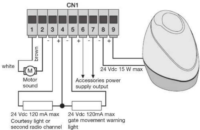
N.B.: Do not change the motor output wiring (terminals 1 and 2) the dip switch 2-2 selects the direction of opening.
| Terminals Description Function | ||
| 1-2 Motor output | Output Output for controlling electric motor 24 Vdc rated power 50 W(terminal number 1 white, terminal number 2 brown) | |
| 3-4 | Courtesy light or second radio channel | Output 24 Vdc maximum load 85 mA, can be programmed as a timed output (60 seconds) or second radio channel output, see dip switch number 6 (3 = GND / 4 = +24 Vdc). |
| 4-5 | Warning light output | Output 24 Vdc maximum load 85 mA, flashes slowly when opening, on with stationary open gate, flashing fast when closing and off with gate closed (4 = 24 Vdc / 5 = GND). |
| 6-7 | Accessories power supply output | Output 24 Vdc maximum 300 mA for supplying the photocells and accessories (6 = +24 Vdc, 7= GND) |
| 8-9 | Output for flashing light | Output 24 Vdc maximum load 15 W for flashing light (8 = GND, 9 = +24 Vdc). |
The sum of the absorptions of the 2CAN, AUX and -VA outputs must not exceed 500 mA.
Input description table:
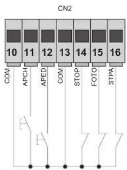
The control unit is supplied with jumpered normally closed inputs (STOP, PHOTO and STPA) remove the jumper from the input you are going to use.
flowchart
graph TD
    A["COM"] --> B["APCH"]
    B --> C["APED"]
    C --> D["COM"]
    D --> E["STOP"]
    E --> F["FOTO"]
    F --> G["STPA"]
    H["CN2"] --> I["10"]
    H --> J["11"]
    H --> K["12"]
    H --> L["13"]
    H --> M["14"]
    H --> N["15"]
    H --> O["16"]
| Terminal number Description Input type | ||
| 10-13-18 Control inputs common (permanent GND) | - | |
| 11 Sequential control | input, to govern the complete travel of the gate | normally open |
| 12 Sequential control | input, to govern the pedestrian travel of the gate | normally open |
| 14 Input for stopping | the gate Normally closed | |
| 15 Photocell input, active during gate closing | Normally closed | |
| 16 Input for edges or | internal photocell, active during gate closing and opening | Normally closed |
| 17 Opening limit switch | input with dip switch 2-2 offClosing limit switch input with dip switch 2-2 on | Normally closed |
| 19 Closing limit switch | input with dip switch 2-2 offOpening limit switch input with dip switch 2-2 on | Normally closed |
Fig. 6

4.3 Connecting control buttons and key switch
Normally open contacts (the red AP/CH or APED LEDS light up when the selector or buttons connected in parallel are operated):
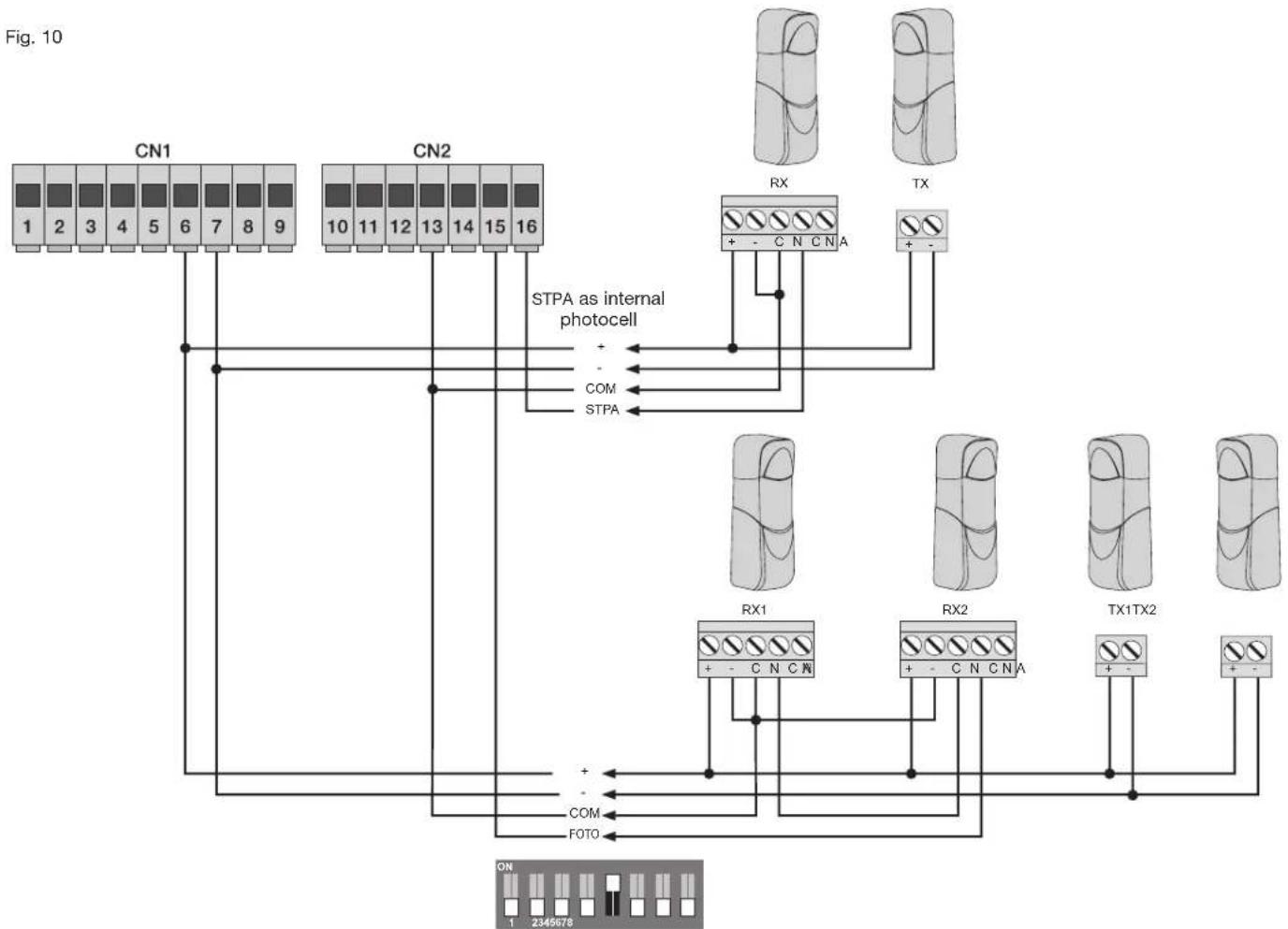
4.4 Connecting photocells
Normally closed contact (when the photocells are not engaged the FOTO LED must be on), if not used then jumper between COM. and FOTO, you must observe the polarity of the power supply for the photocells:
Fig. 7

flowchart
graph TD
    A["CN1"] --> B["1"]
    A --> C["2"]
    A --> D["3"]
    A --> E["4"]
    A --> F["5"]
    A --> G["6"]
    A --> H["7"]
    A --> I["8"]
    A --> J["9"]
    K["CN2"] --> L["10"]
    K --> M["11"]
    K --> N["12"]
    K --> O["13"]
    K --> P["14"]
    K --> Q["15"]
    K --> R["16"]
    S["RX1"] --> T["+ - C N C N R"]
    U["RX2"] --> V["+ - C N C N A"]
    W["TX1TX2"] --> X["+ -"]
    Y["COM"] --> Z["FOTO"]
    AA["FOTO"] --> AB["+"]
    AC["+"] --> AD["-"]
4.5 Connecting sensitive edge or internal photocell
With edge or photocell not engaged the STPA LED must be on, see dip switches 1-4 and 1-7. If not used, jumper between COM and STPA. If a sensitive edge is connected, dip switch number 4 must be set ON and dip switch number 7 selects the type of edge (OFF with normally closed contact or edge ON with balancing resistor of 8.2 K Ohm), the edge tripping reverses the gate movement for approximately 10 cm.
4.5.1 Connecting resistive sensitive edge
Fig. 8
Example for DIP in OFF position:

Example for DIP in ON position:

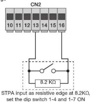

Edge connection to Switch

4.5.2 Connecting internal photocell
If the STPA input is connected to the photocell receiver, set the dip switch number 1-4 to OFF (if the internal photocell is engaged the gate will stop, both when opening and when closing, and then it will remain stationary until the photocell is freed, to then start again with opening).
Fig. 9

flowchart
graph TD
    A["CN1"] -->|1 2 3 4 5 6 7 8 9| B["STPA as internal photocell"]
    C["CN2"] -->|10 11 12 13 14 15 16| D["RX"]
    E["STPA"] -->|+ -| F["COM"]
    G["CN"] --> H["12345678"]
4.5.3 Connecting photocells with photo-test function active
If the photo-test function is activated (the control unit checks the operation of the photocells, see dip switch 5 ON), respect the following connection (each time the motor starts the control unit cuts off power to the transmitter of the photocell to check their operation):
flowchart
graph TD
    A["CN1"] -->|STPA as internal photocell| B["CN2"]
    B -->|STPA as internal photocell| C["RX"]
    B -->|STPA as internal photocell| D["TX"]
    C --> E["RX1"]
    C --> F["RX2"]
    C --> G["TX1TX2"]
    D --> H["FOTO"]
    E --> I["ON 1 2345678"]
    F --> J["ON 1 2345678"]
    G --> K["ON 1 2345678"]
4.6 Stop button connection
Stop button connection, normally closed contact, opening the contact causes the gate to stop and suspends the automatic closing time (when the button is not engaged, the STOP LED should be lit), if not used then jumper between COM and STOP.
Fig. 11

N.B. If the system has no photocells, sensitive edges or stop buttons (the FOTO, STPA and STOP inputs must be jumpered with the common, terminal 13), do not activate the photo-test function.
4.7 Connecting the aerial
The 17 cm rod is supplied pre-wired, to increase the range connect the aerial art. ZL43 as shown in the figure:

5 Description of the LEDs in the circuit:
| Abbreviation Description | |
| AC Shows whether there is mains power (lit if there is mains voltage) | |
| STPA | Displays the status of the STPA input (terminal 16), if not engaged the green LED remains lit, if not used then jumper between terminal COM and STPA |
| AP/CH | Displays the status of the AP/CH input (terminal 11), if not engaged the red LED remains off |
| APED | Displays the status of the APED input (terminal 12), if not engaged the red LED remains off |
| STOP | Displays the status of the STOP input (terminal 14), if not engaged the green LED remains lit, if not used then jumper between terminal COM and STOP |
| FOTO | Displays the status of the FOTO input (terminal 15), if not engaged the green LED remains lit, if not used then jumper between terminal COM and FOTO. |
| FCAP | Displays the status of the opening limit switch with dip2-2 off, the green LED goes out when the gate is fully open.Displays the status of the closing limit switch with dip2-2 on, the green LED goes out when the gate is fully closed. |
| FCCH | Displays the status of the closing limit switch with dip2-2 off, the green LED goes out when the gate is fully closed.Displays the status of the opening limit switch with dip2-2 on, the green LED goes out when the gate is fully open. |
| ENC.A | Displays the encoder A input, on steady when the motor is moving at cyclical speed, flashing during slowdown, off with the motor stopped. |
| ENC.B | Displays the encoder B input, on steady when the motor is moving at cyclical speed, flashing during slowdown, off with the motor stopped. |
| DL12 | Displays the programming status of the travel and of the radio control learning (two-colour LED) |
Buttons in the circuit:
| Abbreviation Description | |
| AP/CH Controls opening and closing the gate | |
| P3 Press to enter travel programming | |
| P2 Press to enter radio controls programming or deletion | |
Preliminary check:
After powering up the control unit the DL12 LED comes on for a second.
Check the LEDS for diagnosis of the inputs, STOP, FOTO and STPA must be on.
Should one of the safety inputs (FOTO, STOP, STPA) not be used, insert a jumper between COM and the input not used.
6 Quick programming
Procedure for facilitated gate travel programming:
N.B. Before starting programming, check the dip switch 2-2 (OFF opening to left, ON opening to right)

- Move the gate to approximately 1 metre from closing.
- Keep button P3 pressed for 2 seconds (the red DL12 LED starts flashing slowly), release button P3.
- Press the AP/CH button, the gate continues until the closing limit switch trips, to then start again with opening at reduced speed.
- On reaching the magnetic limit switches when opening, the gate starts again with closing until the limit switch trips.
- The DL12 LED turns off, the control unit has saved the travel of the gate, aligning with the default parameters, with a distance for slowing down of 50 cm when opening and 75 cm when closing, before the magnetic limit switches.
If, during programming, the operations are reversed, do not change the wiring of the electric motor (terminal 1 and 2) and of the limit switches (terminal 17-19), but check the dip switch 2-2 (OFF opening the gate to the left, ON opening the gate to the right).
N.B.: If the wires of the electric motor power supply are reversed, with the opening command the control unit signals the error via the DL12 LED blinking and the flashing light (see error message table).
Procedure for saving a remote control:
- Press the P2 button for approximately 2 seconds, the DL12 LED with a green light flashes slowly, release button P2.
- The control panel is waiting to learn a remote control (timeout 20 seconds).
- Press the button on the remote control to be saved, the DL12 LED illuminates with a steady green light for approximately 2 seconds, to then switch off.
Repeat the same procedure to save other remote controls. The maximum capacity is 200 remote controls.
On reaching the maximum capacity (200 radio controls) being saved on the remote control (the green DL12 LED flashes), on pressing the button of the new transmitter to be saved, the green DL12 LED makes 3 quick flashes.
N.B.: The first saved remote control configures the control panel to accept only remote controls with a rolling code or only remote controls with a fixed 12-bit code.
7 Complete programming
Customized travel programming
N.B.: Before starting to program check dip switch 2-2 (OFF opening to the left, ON opening to the right) and dip switch 2-1 must be in the OFF position (operation with limit switch).
- Move the gate to approximately 1 metre from closing.
- Keep button P3 pressed for 4 seconds (the red DL12 LED starts flashing rapidly), release button P3
- Press the AP/CH button, the gate closes until the closing limit switch trips, to then start again with opening.
- Before the gate gets to be fully open, press the AP/CH button and the control unit will save the point for starting to slow down when opening
- The gate continues slowing down until the opening limit switch trips, to then restart with closing
- Before the gate gets to be fully closed, press the AP/CH button and the control unit will save the point for starting to slow down when closing
- The gate continues slowing down until the closing limit switch trips, to then restart with opening
- Press the AP/CH button to fix the space for pedestrian opening (when controlling with the Aped input the gate opens by the space set here), the gate starts closing, until the closing limit switch trips.
- The control unit saves the set travel and the DL12 LED goes out, the procedure for programming the travel is successfully concluded.
Programming or deleting radio controls
Save the remote control button to control the AP/CH input: press the P2 button until the DL12 LED with a green light begins to flash slowly, release the button and press the button on the remote control to save, the DL12 LED comes on with a green light for 1 second to confirm saving. To save other remote controls, repeat the above procedure.
Save the remote control button to control the APED input: press the P2 button until the DL12 LED with a green light begins to flash quickly, release the button and press the button on the remote control to save, the DL12 LED comes on with a green light for 1 second to confirm saving the remote control button for operating pedestrian opening. To save other remote controls, repeat the above procedure.
To delete a saved remote control: press the P2 button until the DL12 LED with a green light begins to flash very quickly, release the button and press the button on the remote control to delete, the DL12 LED comes on with a green light for 1 second to confirm deleting the remote control button. To save other remote controls, repeat the above procedure.
To delete all the remote controls: cut off the power to the control panel, also disconnect any batteries.
Press and hold down the button P2, reconnect the power supply to the control panel without releasing the button P2 until the DL12 LED goes out
The maximum capacity is 200 radio controls, on reaching the maximum capacity being saved on the remote control (the green DL12 LED flashes), on pressing the button of the new transmitter to be saved, the green DL12 LED makes 3 quick flashes to indicate the memory is saturated.
N.B. The first saved remote control configures the control panel to accept only remote controls with a rolling code or only remote controls with a fixed 12-bit code.
8 Programmable functions:
The table shows the functions that can be activated via the dip switches, the control unit reads the dip switches with the gate stationary on closing:
| Dip switch number | Status of dip switch | Description |
| DIP 1-1 OFF Automatic closing function off | ||
| DIP 1-1 ON Automatic closing function on | ||
| DIP 1-2 | OFF | Condominium function on (during gate opening it is not possible to stop the movement with the remote control or AP/CH inputs) |
| DIP 1-2 ON With each command the gate: opens, stops, closes, stops | ||
| DIP 1-3 OFF Pre-flashing off | ||
| DIP 1-3 | ON | Pre-flashing on, before the gate moves the flashing light comes on for 3 seconds |
| DIP 1-4 OFF STPA input as internal photocell | ||
| DIP 1-4 ON STPA input as sensitive edge | ||
| DIP 1-5 OFF Photo-test function off | ||
| DIP 1-5 | ON | Photo-test function on (photocell checking with each command) see paragraph 4.6.3 |
| DIP 1-6 OFF Second radio channel associated with pedestrian gate opening | ||
| DIP 1-6 | ON | Second radio channel associated with activation for 1 second of 2can output (terminal 3 and 4) |
| DIP 1-7 OFF Sensitive edge with normally closed contact | ||
| DIP 1-7 | ON | Resistive sensitive edge, normally open contact with balancing resistance of 8.2 K Ohm in parallel |
| DIP 1-8 OFF Close immediately function off | ||
| DIP 1-8 | ON | Enables the close immediately function (the photocell tripping takes the automatic closing time to 5 seconds, upon its disengagement) |
| DIP 2-1 OFF not used | ||
| DIP 2-1 ON not used | ||
| DIP 2-2 OFF For opening the gate to the left | ||
| DIP 2-2 ON For opening the gate to the right | ||
Adjustment trimmer
| Trimmer Description | |
| TR1 | |
| TR2 Force (adjusts the motor torque) | |
| TR3 Slowdown speed | |
| TR4 Cycle speed | |
| TR5 Automatic closing time (adjustable from 1 to 120 seconds) | |
N.B.: On varying the trimmers TR3 (slowdown speed) or TR4 (cycle speed), the red DL12 LED flashes quickly, issue a command with the button APCH. The gate opens and closes completely to save the absorptions during the travel with the new speeds, when fully closed the DL12 LED turns off, saving the new values.
The error messages are displayed by the DL12 LED and the flashing light (terminal number 8 and 9).
Error message key:
| Number of flashes Description | |
| 2 Photocell test failed (incorrect wiring or photocells busy) | |
| 3 Detected a problem in the circuit that activates the motor | |
| 4 Problem with encoder (encoder not present or electric motor wiring reversed) | |
| 5 Serious error on EEPROM (U2 component missing or damaged) | |
| 6 The travel end time has elapsed (U2 component missing or damaged) | |
| 7 F2 fuse blown | |
| 8 Motor overcurrent error | |
| 9 Motor power cables (terminals 1-2) reversed | |
At the end of programming check the automatic gate system works properly by simulating the photocells and sensitive edges tripping. In the event of malfunctioning, check the wiring, the dip switch 2-2 for selecting the direction of opening.
9 Installing batteries
Insert the battery charging circuit in connector CN8 and connect the batteries, with battery-only operation the speed of the motor is 15% lower than the speed with mains power, the number of operations with the batteries depends on the number of photocells in the system and the length of the gate. When operating on batteries only, the AC LED is off, the 2CAN and AUX outputs are not active and the accessories are not supplied with the gate stationary.
10 - Troubleshooting:
| Problem Cause Solution | ||
| The automatic gate system does not work No | mains supply | Check the power line switch |
| Blown fuses | Replace the fuses with others of the same value | |
| Control and safety inputs not working | Check the diagnosis LEDS (stop, STPA and photo must be on) | |
| You cannot save the remote controls Safety devices open | Check the diagnosis LEDS (stop, STPA and photo must be on) | |
| Batteries of the remote control discharged | ||
| Remote control not compatible with the first one saved | ||
| Reached memory saturation | ||
| The remote control does not work Batteries of the remote control discharged Replace the batteries | ||
| You cannot enter travel programming Safety devices open Check the diagnosis LEDS (stop, STPA and photo must be on) | ||
| As soon as the gate starts it stops and reverses | Motor torque not sufficient Increase the force with the trimmer TR2 | |
| During slowdown, the gate stops and reverses | Slowdown speed too low Increase the value of trimmer TR3 | |
| The gate does not stop with the limit switches tripping, where applicable | The magnetic sensor cannot read the magnet Move | the magnet near to the sensor |
| Check the LEDS of the limit switches. | ||
| Check dip switch number 2-1 for limit switch presence and dip switch 2-2 for direction of gate opening. | ||
EC DECLARATION OF CONFORMITY
(Declaration of incorporation of partly completed machinery Annex IIB Directive 2006/42/EC)
No.: ZDT00434.00
The undersigned, representing the following manufacturer
Elvox SpA
Via Pontarola, 14/A - 35011 Campodarsego
(PD) Italy
herewith declares that the products
CONTROL BOARD - RS SERIES
Articles RS01, RS02, RS03, RS04, RS05, RS06, RS07, RS08, RS12, RS13, RS14
are in conformity with the provisions of the following EU Directive(s) (including all applicable amendments) and that all of the following standards and/or specifications have been applied
EMC Directive 2004/108/EC: EN 61000-6-1 (2007), EN 61000-6-3 (2007) + A1 (2011)
R&TTE Directive 1999/5/EC: EN 301 489-3 (2002), EN 300 220-3 (2000)
Machinery Directive 2006/42/EC EN 60335-2-103 (2003) + A11 (2009),
EN 13241 (2003) + A1 (2011), EN 12453 (2000)
He also declares that the product must not be commissioned until the end machine, in which it is to be incorporated, has been declared in conformity, when applicable, with the provisions of Directive 2006/42/EC.
He declares that the relevant technical documentation has been constituted by Elvox SpA, drawn up in accordance with Annex VIIIB of Directive 2006/42/EC and that the following essential requirements have been fulfilled: 1.1.1, 1.1.2, 1.1.3, 1.1.5, 1.1.6, 1.2.1, 1.2.2, 1.2.6, 1.3.1, 1.3.2, 1.3.3, 1.3.4, 1.3.7, 1.3.8, 1.3.9, 1.4.1, 1.4.2, 1.5.1, 1.5.2, 1.5.4, 1.5.5, 1.5.6, 1.5.7, 1.5.8, 1.5.9, 1.6.1., 1.6.2, 1.7.1, 1.7.2, 1.7.3, 1.7.4.
He undertakes, in response to an adequately justified request from the national authorities, to present all the necessary supporting documentation concerning the product.
Campodarsego, 29/04/2013
The Chief Executive Officer
Note: The contents of this declaration match what was declared in the latest revision of the official declaration that was available before this manual was printed. This text has been adapted for editorial purposes. A copy of the original declaration can be required to Elvox SpA

- Indice: Pagina
- WARNINGS FOR THE INSTALLER
- 2002/96/EC Directive (WEEE).
- CE
- Characteristics
- Key:
- Risk assessment
- Electrical wiring harnesses:
- System set-up
- Power supply line wiring
- Wiring for flashing light, courtesy light and gate movement warning light
- Input description table:
- Connecting control buttons and key switch
- Connecting photocells
- Connecting sensitive edge or internal photocell
- Connecting resistive sensitive edge
- Connecting internal photocell
- Connecting photocells with photo-test function active
- Stop button connection
- Connecting the aerial
- Description of the LEDs in the circuit:
- Buttons in the circuit:
- Preliminary check:
- Quick programming
- Procedure for saving a remote control:
- Complete programming
- Customized travel programming
- Programming or deleting radio controls
- Programmable functions:
- Installing batteries
- EC DECLARATION OF CONFORMITY
- CONTROL BOARD - RS SERIES
- The Chief Executive Officer
Brand : Vimar
Model : RS05
Category : Electronic board