9450 Sport - Pool POLARIS - Free user manual and instructions
Find the device manual for free 9450 Sport POLARIS in PDF.
User questions about 9450 Sport POLARIS
0 question about this device. Answer the ones you know or ask your own.
Ask a new question about this device
Download the instructions for your Pool in PDF format for free! Find your manual 9450 Sport - POLARIS and take your electronic device back in hand. On this page are published all the documents necessary for the use of your device. 9450 Sport by POLARIS.
USER MANUAL 9450 Sport POLARIS
natural_image
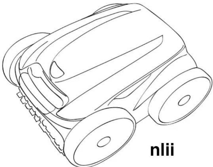
Line drawing of a toy car with visible wheels and a textured grip (no text or symbols)E
E
| ⚠️E n hing h h n h in l ning n in nn si in his n l his s si n h is li ns n l i i in l i n h is i i in hi h h ill ins ll h s hs l l i ns is nh nn s hs l l i n is s h in in s ssin l ihsi i n in l i n ins ll inn in nn s h ll h ins ins in his n l n ll ins ll inn i n ill i h n |
| ⚠️ E E EE ins n h g n n is i s is l l l l i ns i ns is in l i i in l i i s ins ll ls ll s ign sl ls in l ssn i si n ig n l l in il ns is ni ll gn n in i n ssi nn l s is n in ns ins ll in l in nn i n is in li n l s nsign s sn n l ins ll in l ills in in i nn l lg nl |
| ⚠️ E EEs ins n l s is i n nl l s ins l n is n isi ss ls l l s En l s ning ns l ls lig i l s ns l s n sin l n in i si in nl is in l ins l in n ni in i s l sins ins ns n l s sgi n ns ins l s l sig s l s n is l sins ins n s El in ll in ls is s ni ins ins sl n s l i i l sins ns ls ins l in ins nl lg n |
Inns
i n n ns i ns
Section 2. Cleaner Specifications
i n ss l
3.1 Unpacking 5
3.2 Assembling the Transport Caddy 5
3.3 Connecting the Control Unit to the Caddy...... 7
3.4 Connecting to Power Source....8
i n i n
4.1 Submerging the Cleaner 9
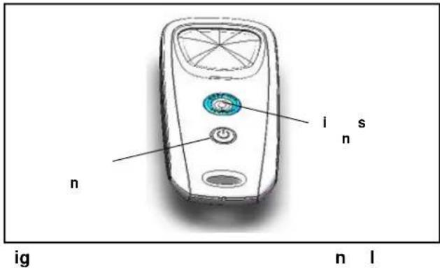
4.2 The Polaris 9350/P935 Cleaner Control Unit ... 10
4.3 The Polaris 9450 Sport/P945 Cleaner Control Unit....10
4.4 The Polaris 9550 Sport/P955 Cleaner Control Unit....11
4.5 Starting the Cleaner .....11
4.6 Stopping the Cleaner and Removing from the Pool.... 12
4.7 Operating the Cleaner with the Remote Control (9550 Sport/P955 only) 12
4.8 Synchronizing the Remote Control.... 13
4.9 Storing the Cleaner 13
i n g ing h l n
5.1 Displaying Current Day and Time.... 14
5.2 Changing the Clock Day and Time.... 14
5.3 Changing Default Cleaning Times 14
5.4 Programming Cleaning Cycles.... 15
5.5 Canceling Cleaning Cycles 15
i n l ning n in n n
6.1 Cleaning the Filter Canister.... 16
6.2. Cord Tangling 17
6.3 Replacing the Brushes 18
6.4 Replacing the Tires....19
i n s
i n l sh ing
8.1 Using the Information LED for Troubleshooting (9350 / P935 Cleaner) 21
8.2 Viewing Cleaner Status Information for Troubleshooting (9450 Sport/P945 and 9550 Sport/P955)....21
8.3 General Troubleshooting 22
8.4 Control Unit Error Codes
(9450 Sport/P945 and 9550 Sport/P955)...... 23
THANK YOU FOR PURCHASING THE POLARIS CLEANER.
YOUR POLARIS ROBOTIC CLEANER HAS BEEN DESIGNED AND MANUFACTURED TO BE EASILY INSTALLED AND TO PROVIDE LOW MAINTENANCE OPERATION. PRIOR TO INSTALLING YOUR NEW POLARIS CLEANER, PLEASE DO THE FOLLOWING:
1) Complete and return the warranty card.
2) Record your purchase information on the spaces provided below.
3) Attach your invoice (or a copy) to this page.
Taking these steps will help ensure prompt warranty service, should it be required. If service is required, please contact your original dealer. If the original dealer does not perform warranty service, please visit www.polarispool.com to locate an independent service company near you. If you are unable to locate a service company, please call our Technical Support department at 1-800-822-7933.
RECORD YOUR POLARIS CLEANER DATA HERE:
Date of Purchase ____ Purchased From ____ Serial Number: ____
(located on machine head)
City ____ State/Province ____ Zip/Postal Code ____
n
This device complies with Part 15 of the FCC Rules and IC licence-exempt RSS standard. Operation is subject to the following two conditions: (1) this device may not cause harmful interference, and (2) this device must accept any interference received, including interference that may cause undesired operation.
E This equipment has been tested and found to comply with the limits for a Class B digital device, pursuant to part 15 of the FCC Rules. These limits are designed to provide reasonable protection against harmful interference in a residential installation. This equipment generates, uses and can radiate radio frequency energy and, if not installed and used in accordance with the instruction, may cause harmful interference to radio communications. However, there is no guarantee that interference will not occur in a particular installation. If this equipment does cause harmful interference to radio or television reception which can be determined by turning the equipment off and on, the user is encouraged to try to correct interference by one or more of the following measures:
- Reorient or relocate the receiving antenna.
- Increase the separation between the equipment and receiver.
- Connect the equipment into an outlet on circuit different from that to which the receiver is connected.
- Consult the dealer or an experienced radio/TV technician for help.
Any changes or modifications not expressly approved by the part responsible for compliance could void the user's authority to operate the equipment.
E This device complies with FCC and IC RF radiation exposure limits set forth for general population. This device must be installed to provide a separation distance of at least 20cm from all persons and must not be co-located or operating in conjunction with any other antenna or transmitter.
Under Industry Canada regulations, this radio transmitter may only operate using an antenna of a type and maximum (or lesser) gain approved for the transmitter by Industry Canada. To reduce potential radio interference to other users, the antenna type and its gain should be so chosen that the equivalent isotropically radiated power (e.i.r.p.) is not more than that necessary for successful communication.
i n n ns i ns
Congratulations on purchasing the Polaris Robotic Cleaner. Please read through the entire manual before installing your new robotic pool cleaner. Your cleaner must be installed and operated as specified.
E
!
il l ih h ll ing nings n s l in n n in l i n h
EEEE
To reduce risk of electrical shock:
- Connect unit to receptacle protected by a ground fault circuit interrupter (GFCI). Such a GFCI receptacle should be provided by a qualified installer and should be tested on a routine basis. To test the GFCI, push the test button. The GFCI should interrupt power. Push the reset button. Power should be restored. If the GFCI fails to operate in this manner, the GFCI is defective. If the GFCI interrupts power to the pump without the test button being pushed, a ground current is flowing, indicating the possibility of an electric shock. Do not use this product. Disconnect the cleaner and have the problem corrected by a qualified service representative before using.
- Per the United States National Electrical Code ^ (NEC ^ ), keep the control unit at least five (5) feet from the edge of the (pool/spa) water. In Canada, the Canadian Electrical Code (CEC) requires a minimum distance of 3m (10 ft.) to be maintained between the pool edge and the control unit. Never submerge the control unit.
- Do not enter pool while the Polaris cleaner is in water.
- Do not bury cord. Locate cord so as to prevent it from being damaged by lawn mowers, hedge trimmers and other equipment.
- To reduce the risk of electrical shock, do not use the Polaris robotic cleaner or control unit if the cord is worn or damaged. Contact Zodiac Pool Systems, Inc. Technical Support immediately for proper servicing and replacement of the damaged cord.
- Double insulation—For continued protection against possible electric shock, use only identical replacement parts when servicing. Do not attempt repair of the Polaris robotic cleaner, control unit, power cord, or floating cable.
• NEVER OPEN CONTROL UNIT. - DO NOT USE AN EXTENSION CORD TO CONNECT THE UNIT TO ELECTRIC SUPPLY; PROVIDE A PROPERLY LOCATED GFCI RECEPTACLE. THE CONTROL UNIT SHOULD BE PLACED NEAR THE GFCI RECEPTACLE BOX.
EE
• To reduce the risk of injury, do not permit children to operate this product.
- Do not let anyone, especially small children, sit, step, lean, or climb on any equipment installed as part of your pool's operational system.
!
ll i ih h ll ing nings l s g l i n s n l in
- The Polaris cleaner must be installed and operated as specified.
- This product is intended for use with permanently-installed pools. Do not use with storable pools. A permanently-installed pool is constructed in or on the ground or in a building such that it cannot be readily disassembled for storage. A storable pool is constructed so that it is capable of being readily disassembled for storage and reassembled to its original integrity.
- Clean the filter canister in the Polaris cleaner after each use.
- Do not use the product in your pool if the water temperature is above 95^ (35°C) or below 55^ (13°C).
!
USE OF THE POLARIS ROBOTIC CLEANER IN A VINYL LINER POOL
Certain vinyl liner patterns are particularly susceptible to rapid surface wear of pattern removal caused by objects coming into contact with the vinyl surface, including pool brushes, pool toys, floats, fountains, chlorine dispensers, and automatic pool cleaners. Some vinyl liner patterns can be seriously scratched or abraded simply by rubbing the surface with a pool brush. Ink from the pattern can also rub off during the installation process or when it comes into contact with objects in the pool. Zodiac Pool Systems, Inc., is not responsible for, and the Limited Warranty does not cover, pattern removal, abrasion or markings on vinyl liners.
Section 2. Cleaner Specifications
2.1 General Specifications
The general specifications for the cleaner are as follows:
| nls l lg | 100-125 VAC, 60 Hz |
| l l g | 30 V DC |
| ns ll l | 150 W max |
| l l ng h | 60 ft (18 m)70ft (21m) |
| l n si | 16.9 x 18.9 x 10.6 in. (43 x 48 x 27 cm) |
| igh l n | 21 lbs. (9.5 kg) |
| igh | 42 lbs. (19 kg) |
| il in | All-purpose filter canister |
| l l ng hs | Variable programming |
The cleaner is a double-insulated product. A double-insulated electrical appliance is one which has been designed in such a way that it does not require a safety connection to ground. The basic requirement for double-insulation is that no single failure can result in dangerous voltage becoming exposed so that it might cause an electric shock and that this is achieved without relying on an earthed (grounded) metal casing. This is achieved by having two (2) layers of insulating material surrounding live parts or by using reinforced insulation. Therefore, devices having double-insulated construction, such as this cleaner, do not utilize a grounded (three-prong) cord/plug.
i n ss l
ning
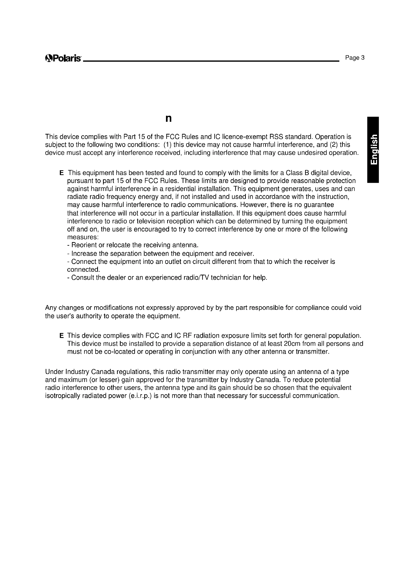
The packaging should contain the following items:
- Polaris cleaner
- Control unit
• Remote Control (9550 Sport/ P955 only) - Transport and storage caddy assembly components (Figure 1)
(a) handle frame
(b) support blocks (x 2)
(c) wheels (x 2)
(d) wheel locking clips (x 2)
(e) wheel axle / hubcap (x 2)
(f) base unit
(g) cleaner hook
(h) caddy handle
(i) remote control & attachment hook
natural_image
Exploded view diagram of a car interior showing components like steering wheel, gear shift, and bracket (no text or labels)ignssslnns
When unpacking the cleaner and its components:
- Check to make sure each component is in the box.
- Check cleaner and components for damage during transport.
- If there are any missing parts or damage, contact Zodiac® Technical Support at 1-800-822-7933.
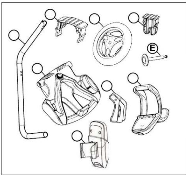
ss linghns
- Unscrew the handnut from the base unit (Figure 2).
natural_image
Technical line drawing of a mechanical component with a rotating knob and adjustment arrow (no text or symbols)ignnsni
-
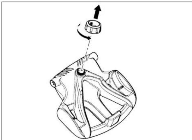
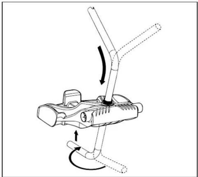
Insert the metal handle frame tubing into the base unit with notch end at the top, then rotate so the bends are away from you. (Figure 3).
-
Push base unit down (Figure 3) so the metal handle frame is seated in the recess on the underside of the base.
natural_image
Mechanical diagram showing a lever mechanism with arrows indicating motion (no text or symbols)ignnlsni
- Slide the handnut over the tube and twist to tighten onto base unit (Figure 4).

natural_image
Technical line drawing of a mechanical device with a lever and adjustment arrow (no text or symbols)igisnn
-
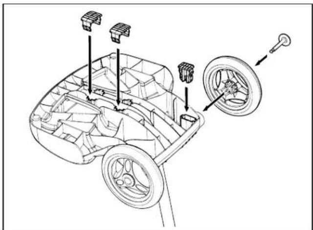
Snap two (2) support blocks into place (Figure 5).
-
Slide axle and hubcap piece through center of wheel and attach to base unit. Snap locking clip into place to secure wheel. Repeat to attach both wheels (Figure 5).
natural_image
Technical line drawing of a car interior showing structural components and wheel assembly (no text or labels)igninlsnh
hls
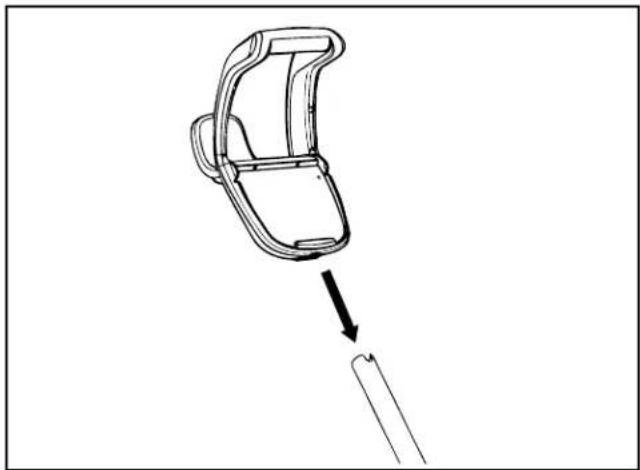
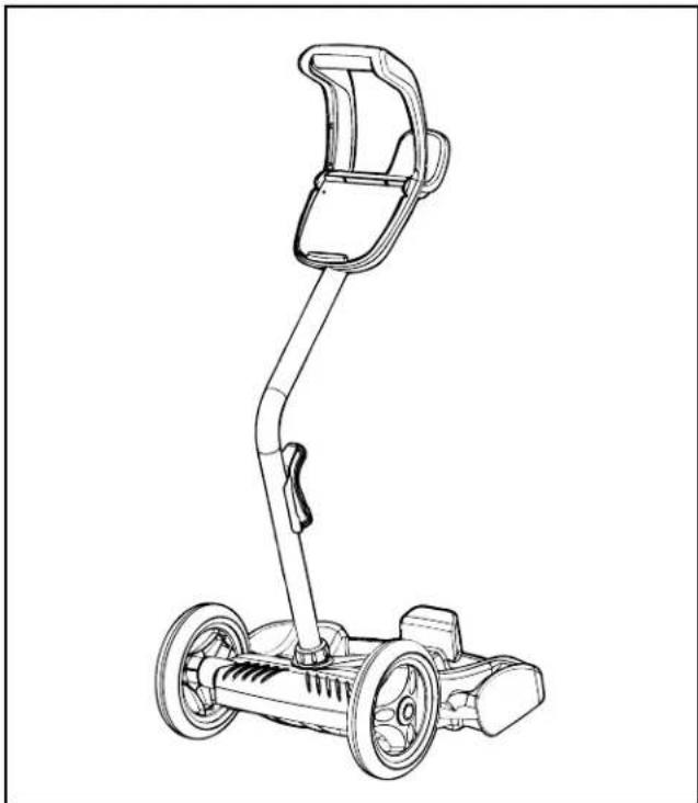
- Slide the control unit base / caddy handle attachment down over the metal tubing until it snaps into place. (See Figure 6).
natural_image
Diagram of a car handle assembly with an arrow indicating direction (no text or symbols)ighnl
- Align cleaner hook pins with the top holes in the handle tube and snap into place (Figure 7).
text_image
Diagram illustrating the use of a device to adjust a car body, with an inset showing the component being inserted.ignIninl
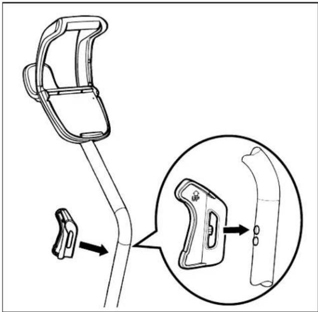
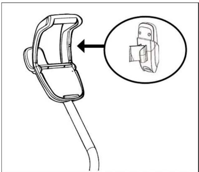
- Locate pin on the remote control holder and align it with the recepticle on the handle of the caddy to attach the remote control unit to caddy (Figure 8).
natural_image
Technical line drawing of a mechanical clamp or bracket with an inset close-up showing a component detail (no text or symbols)ignnllinl
natural_image
Line drawing of a handheld electric motor with attached sensor device (no text or symbols)igllssIns
nninghnlnih
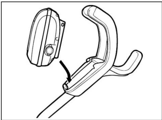
- Align the bottom of the control unit with the notch at bottom of the control unit hook on the caddy (Figure 10).
natural_image
Technical line drawing of a mechanical clamp or bracket assembly with a close-up inset showing the component (no text or symbols)iglignnlniih
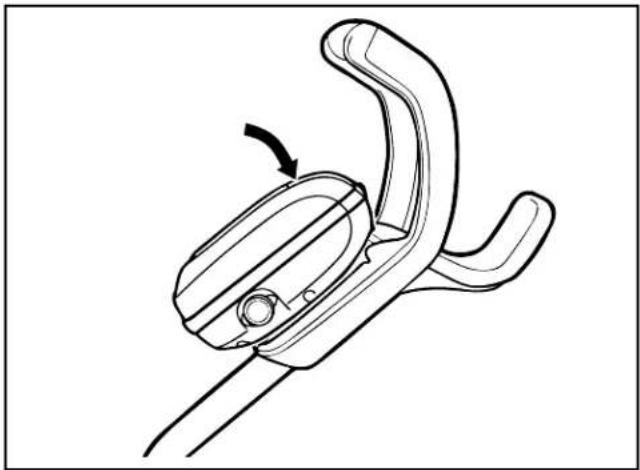
- Press control unit onto the caddy hook until it snaps and locks into position (Figure 11).
natural_image
Line drawing of a mechanical clamp or bracket component with an arrow indicating rotation (no text or symbols)ighhlnnin
nn ing

Failure to comply with the following warnings can result in permanent injury, electrocution or drowning.
EEEE
- : Per NEC ^ requirements, keep the control unit at least five (5) ft. (1.5 m) from the edge of the pool.
- : Per CEC requirements, keep the control unit at least three (3) m (10 ft.) from the edge of the pool.
- Only connect the control unit to a receptacle protected by a ground fault circuit interrupter (GFCI). Contact a certified electrician if you cannot verify that the receptacle is protected by a GFCI.
- Do not use an extension cord to connect the control unit.
- Do not allow anyone to swim while the cleaner is in the pool.
-
The control unit is water-resistant, not waterproof. In order to prevent electrocution, never submerge the control unit or leave exposed to inclement weather.
-
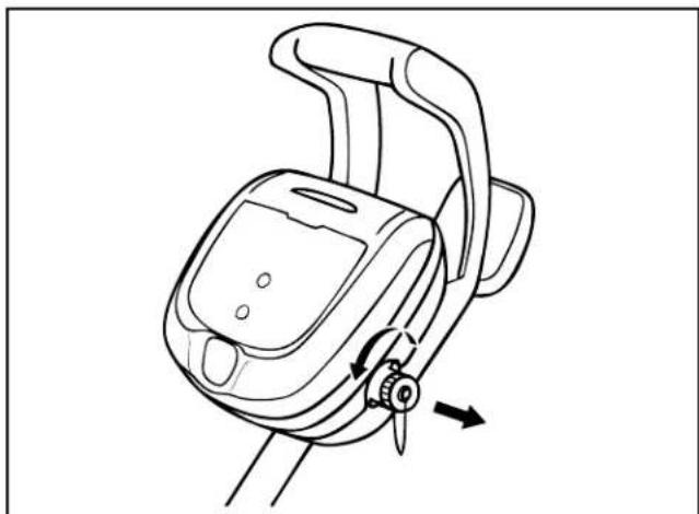
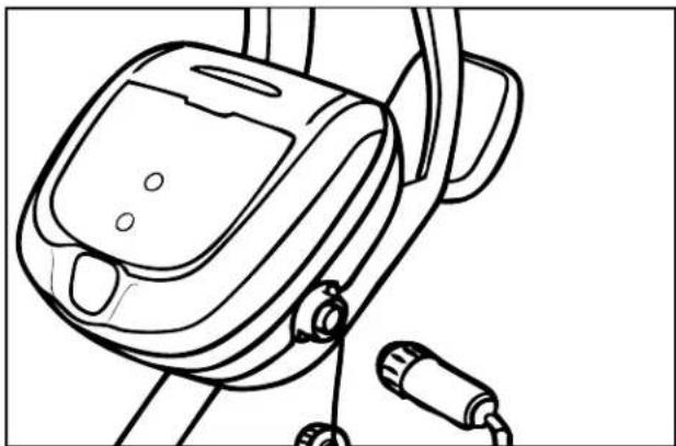
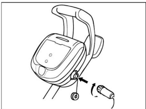
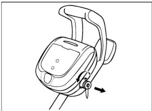
Unscrew the protective cap for the power cable from the side of the control unit by turning counter-clockwise (Figure 12).
natural_image
Line drawing of a mechanical device with a scroll wheel and directional arrow (no text or symbols)igi
natural_image
Line drawing of a handheld device with attached cable and switch (no text or symbols)ignnl
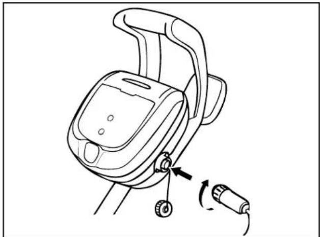
- Grip the notched end of the floating power cable, insert into the control unit, and turn clockwise to tighten. (Figure 13.)
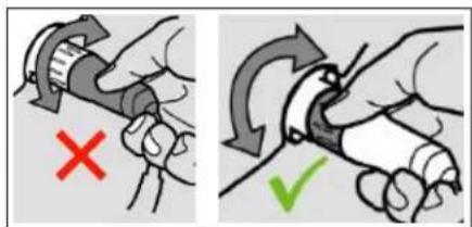
E To avoid damaging the power cable, do not try to twist the entire cable housing (see below).
text_image
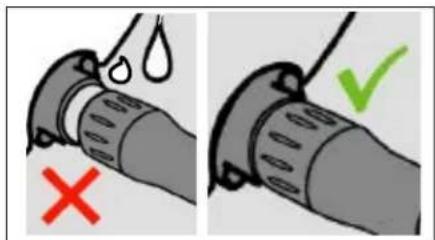
Diagram illustrating hand grip and grip movement with red X and green checkmark indicatorsE To avoid exposing the power cable connector pins to water, be sure the connector is screwed in all the way and there is no gap. (see below).
text_image
Diagram showing correct and incorrect pipe damage with red X mark and green checkmark indicating failureinin

To prevent damage to the cleaner, be sure to adhere to the following guidelines:
- Remove the cleaner from the pool after the cleaning cycle is completed and store on the caddy out of direct sunlight or inclement weather.
- Never lift the cleaner out of the pool by the floating cable. Always use the lift feature to remove cleaner from the pool.
• Take additional care when lifting the cleaner out of the pool. It becomes heavier when filled with water.
• Always remove the cleaner from pool when super chlorinating or adding acid. - Do not handle cleaner while it is in operation.
• Always make sure the cleaner head is fully submerged before you begin operation.
- Clean the filter canister after each cleaning cycle.
- Do not leave your cleaner in the pool on a permanent basis.
- At the end of each cycle, remove the cleaner from the pool. Start at the cleaner head and untangle any coils in the cable before storing the cleaner.
When the control unit is powered on with the floating cable attached, the operating time for the current selected cycle is displayed.
The Polaris robotic cleaner includes a safety feature that automatically stops the cleaner if it is powered on but not submerged in water. For pools equipped with a beach area, this safety feature is programmed to drive the cleaner in reverse and back into the pool when the impeller is out of the water.
ging h l n
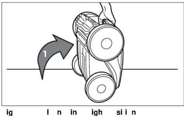
- Submerge the cleaner in the pool and remove any air trapped inside by keeping the unit vertical (Figure 15).
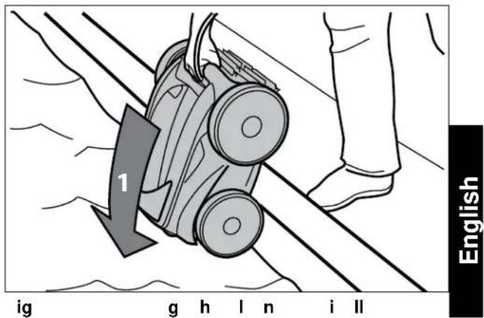
text_image
1 ig g h l n i ll English- Ensure the unit sinks to the bottom of the pool and does not float (Figure 16).
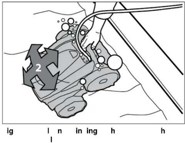
text_image
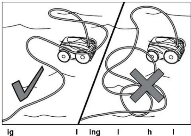
2 ig l n in ing h h- Spread out the floating cable over the pool, ensuring there are no kinks or coils in the cable (Figure 17).
text_image
ig I ing I h IhlisInnIni
text_image
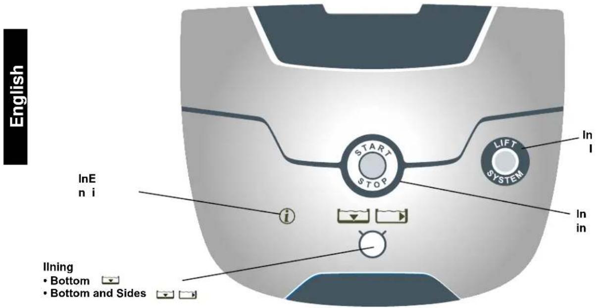
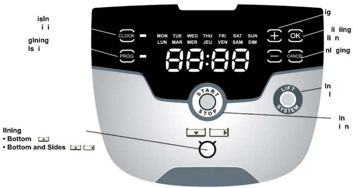
English InE n i i LIFT SYSTEM In I In in Inning • Bottom • Bottom and SideshlisInnlni
text_image
isIn i i glning Is i CLOCK MON TUE WED THU FRI SAT SUN LUN MAR MER JEU VEN SAM DIM PROG. 88:88 + OK Cancel li iing li n nl ging START STOP LIFT SYSTEM In I In i n llning • Bottom • Bottom and Sides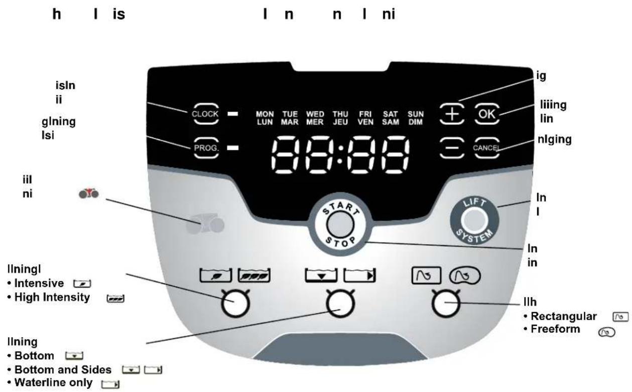
The default cleaning surface setting for the Polaris cleaners is Bottom Surface. To change the current programmed cycle, see Section 5. Programming the Cleaner.
llning ll ls
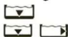
Use ▼ ▶ to change cleaning surface setting.

Toggle between: nl


nis

lin
llningnnsil nl
Use ☐ ☐ ☐ to choose cleaning intensity level.

Toggle between: INTENSIVE

INTENSIVE

HIGH INTENSITY
l l h nl
Use 📄 📋 to choose pool shape.

Toggle between: □ RECTANGULAR

FREEFORM
gin Ining
After selecting the cleaning surface and other options as applicable, press STAR to begin operation.
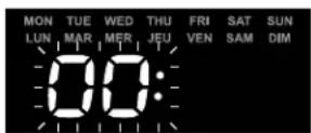
The screen displays the time remaining for the selected cycle. For example, 0:44 on the display indicates that cleaning will be completed in 44 minutes.
E The control unit automatically switches to standby power mode after 10 minutes of inactivity and the display screen turns off. Press any key to exit standby mode. Cleaner will continue to function in standby mode if in the middle of a cleaning cycle.
inghln ninghl
The automated Lift System makes removing the cleaner from the pool simple. The Lift System will move the cleaner toward the edge of the pool then drive it to the surface for removal.
- At the end of the cleaning cycle, or at any time during a cleaning cycle, press to begin the automated lift procedure.
Press and hold the Lift System button to turn cleaner to the left. Cleaner will keep rotating left. Once the cleaner is oriented towards the wall of your choice, release the button.
Press and release the Lift System button and the cleaner will drive up the wall and to the water line and wait to be retrieved.
The screen displays

when the
Lift System is in operation.
E To stop the lift procedure at any time, press.

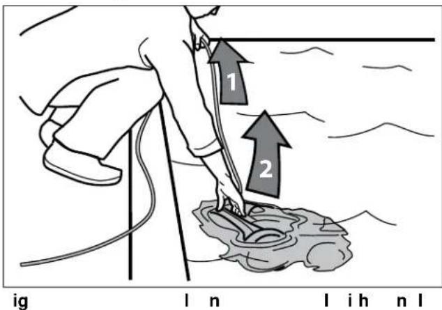
- When the cleaner is within arm's reach, use the handle to remove from the water (Figures 18, 19). Never lift the cleaner out of the pool by the floating cable.
text_image
1 2 ig l n l i h n l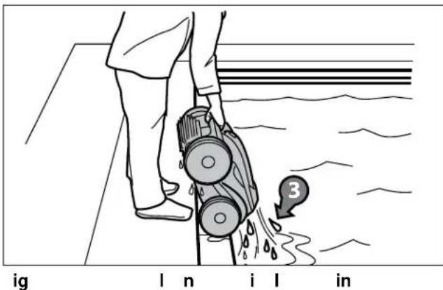
text_image
ig l n i l in 3inghln ihh nlnl
The Polaris 9550 Sport and P955 robotic cleaner comes with a handheld remote control stored on the cleaner caddy next to the control unit. The remote control is factory-synchronized to your cleaner's control unit.
text_image
i s n n ig n l• To turn on the remote control:
Press ⏻ (see Figure 20) and hold for 3 seconds.
The display shows to indicate the cleaner is now operating in remote control mode.
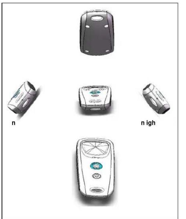
- To pilot the cleaner, point the device toward the cleaner in the water and move directionally as shown in Figure 21.
natural_image
Illustration of four different mobile phone models labeled 'n' and 'n igh', shown in separate views (no text or symbols on devices themselves)ig n l i i n l n s
• To remove the cleaner from the pool using the remote control, press (see Figure 20).
The cleaner rotates left until you release the Lift System button.
nhniinghnl
Even though the remote control is factory-synchronized to your cleaner's control unit, it may be necessary to synchronize again if you need to replace either the control unit or the remote control.
• To synchronize the remote control to the control unit:
Press ⏻ and hold for 3 seconds to turn on remote. Plug the control unit into a power source.
When the display shows the operating time, press

and

ultaneously for six (6) seconds.
- The display shows followed by the normal operating time display to indicate the cleaner is now synched with the remote and ready to begin operating in remote control mode.
inghln
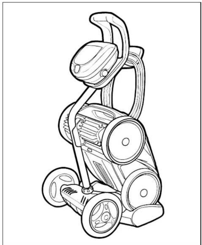
The cleaner must be cleaned regularly using slightly soapy clean water. Do not use solvents such as trichlorethylene or its equivalent. Rinse the cleaner generously using clean water. Do not let your cleaner dry in direct sunlight near the pool. The cleaner must be stored on its caddy so that it dries quickly.
-
Place the rear wheels on the caddy side wedges.
-
Place cleaner in vertical position on the caddy base and clip to hook (Figure 23).
-
Disconnect the cable from the control unit. Replace the protective cap on the control unit.
-
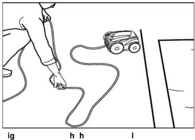
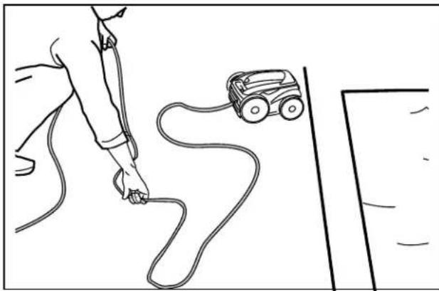
Starting at the cleaner head. Remove all coils and tangles from the cable (Figure 22).
natural_image
Line drawing of a person playing with a small toy car on a path, labeled with letters ig, h, h, l (no text or symbols on the diagram itself)- Loosely coil the power cable starting at the cleaner and moving toward the connection point at control unit. Store the cable by wrapping it around the hook located on the front of the caddy (Figure 23).
natural_image
Line drawing of a lawn mower with three wheels and handle (no text or symbols)ig
In
|
n
ingingh
In
nnl
You can program up to seven preset cleaning cycles to run the cleaner on a specific day and time when you are away from the pool.
E You cannot change programming or display current day and time during a cleaning cycle.
is l ing n n i
- Press CLOCK to display current day and time in 24-hour clock format.

text_image
CLOCK MON TUE WED THU FRI SAT SUN LUN MAR MER JEU VEN SAM DIM PROG. 18:30 n n i is is l s n s h nging h l n i- Press and hold CLOCK for three (3) seconds.

text_image
CLOCK MON TUE WED THU FRI SAT SUN LUN MAR MER JEU VEN SAM DIM PROG.All days of the week flash twice.
-
Press ⊕ or ⊖ buttons to cycle through seven (7) days and display desired day.
-
Press OK to select.

Current hour setting flashes.
- Press ⊕ or ⊖ buttons to cycle through 24 hours and display desired hour setting.
E Control unit is set to display time in 24-hour clock format. Time setting will cycle through 1-24.
5.


Current minutes setting flashes.
6.


Press 📄 or 🚗 buttons to cycle through 1-59 minutes and display desired minutes setting.
7.

Press to select.
8.

Press 📋 to set time and exit the menu.
9.

Press 📄 to display current day and time setting and verify the time you set is correct.
h nging l l ning i s
Use ▼ ▶ to change cleaning surface setting.

Default cleaning times are:
nl 1 hour 30 minutes
n i s
2 hours 30 minutes

lin
Variable cleaning time depending on settings
1.


Press 📄 or 🚗 buttons to increase or decrease cleaning time in 30-minute increments.
2.

to select.
gingInningls
You can program up to seven cleaning cycles.
Program cleaning for either seven consecutive cycles or the same cycle repeated over several weeks
(e.g., every Wednesday and Saturday for three weeks).
- Choose pool cleaning settings to program.
llls
Choose ▼ ▶ to select either bottom of pool or bottom plus sides of pool.
- Choose 📋 to select waterline only in addition to bottom or bottom plus sides options.
- Choose 📄 📌 to select intensive or high intensity level cleaning.
- Choose 📄 📅 to select pool shape.

- Press to view current programmed cleaning cycles.
Cycle day and time is displayed for three seconds.
- When the cleaning cycle you want to change
is displayed, press and hold PROG. for 3 to 5 seconds.
The days of the week flash twice.
Elf the display flashes all zeros, the time has not been set (new cleaner). Day and time must be set before you can program cleaning times, see section 5.2 Changing the Clock Day and Time.


- Press 7 days of the week.

- Press to select.
Hour setting flashes twice.


- Press buttons to cycle through 24 hours.

- Press to select.

Minutes setting flashes zero.


-
Press to cycle through four 15-minute increments (00, 15, 30, or 45).
-
Press to select.


text_image
CLOCK MON TUE WED THU FRI SAT SUN LUN MAR MER JEU VEN SAM DIM PROG.The next day to program flashes.

- Press 📄 to program an additional cleaning cycle for a different day

Press to exit the programming menu
Days of the week are lit indicating programs stored in the control unit memory for that day.
nlinglningls
n l n n i i l g

- Press and hold for 3 to 5 seconds.
The days of the week flash twice.


- Press or buttons to cycle through seven (7) days.
E If the day of the week flashes with no time displayed, there is no program set for that day.

- Press an 📄 for 3 to 5 seconds to delete programming for the selected day.
Press

to exit.
nlllgs

-
Press to make sure you have exited the Programming Menu.
-
Press and hold

programming in the control unit.
The display will turn off for one (1) second. When all programs are cancelled, the current day and time is displayed on the screen with no days of the week lit.
in Inningn
innn

To avoid electric shock and other hazards which could result in permanent injury or death, disconnect (unplug) the cleaner from the power source before performing any cleaning and maintenance.
I ning h il nis
The filter canister should be cleaned at the end of each cycle.
-
Make sure the control unit cable is disconnected from the electrical outlet or the floating cable has been disconnected from the control unit.
-
Remove the cleaner from the water and let the remaining water drain by maintaining the cleaner in the vertical position.
-
Set the unit on its wheels.
-
To remove the filter canister assembly from the cleaner, follow steps 5 through 8.
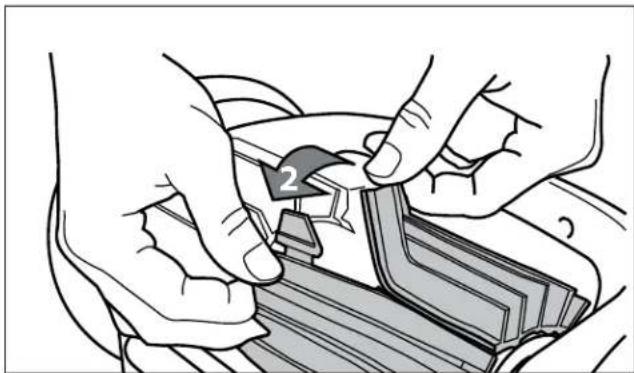
-
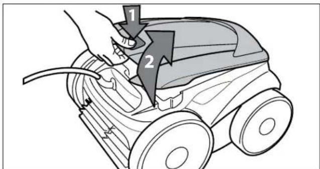
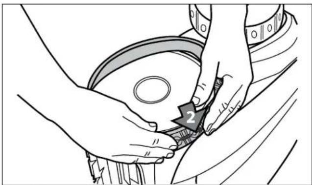
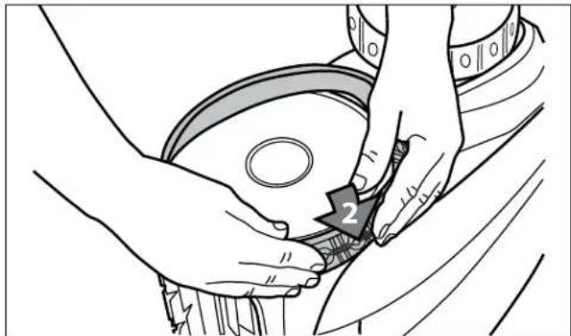
Push the cover lock (1) and lift the cover (2) until it is secured in the vertical position. (Figure 24).
text_image
Diagram showing a hand using a lawn mower to adjust or install a lawn towel, with numbered arrows indicating steps 1 and 2.ig
i l n
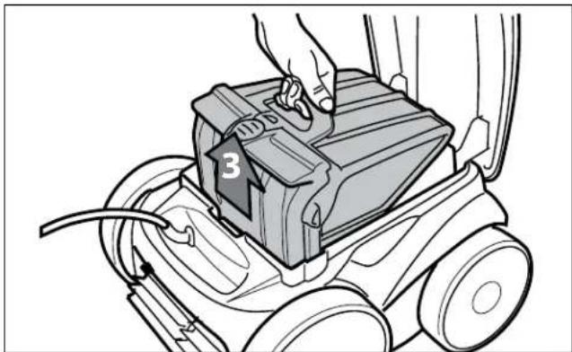
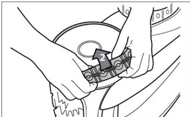
- Remove the filter canister assembly from the body (3), as shown in Figure 25.
natural_image
Line drawing of a hand operating a box labeled '3' on a wheeled cart (no text or symbols beyond label)igilnisssl
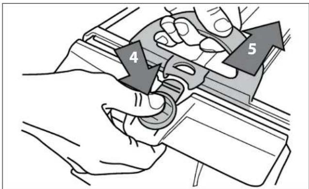
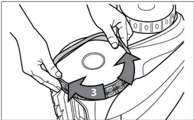
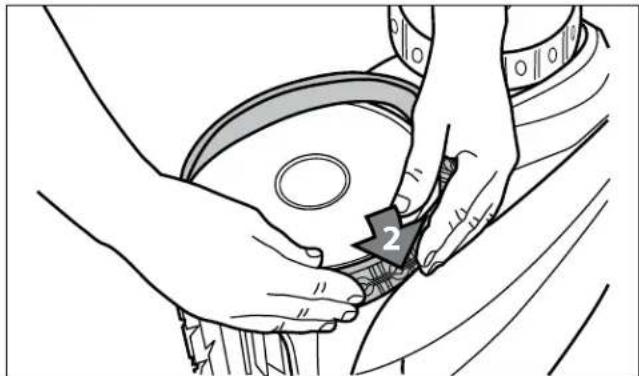
- Push the quick release button on the canister assembly (4) and pull open the filter assembly (5), as shown in Figure 26.
text_image
7igshilnis
text_image
4 5ignilnisssl
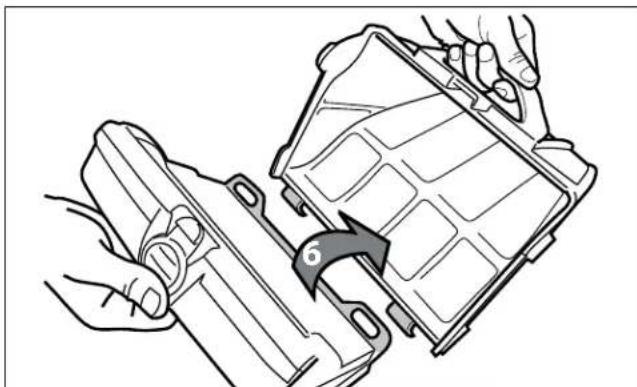
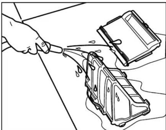
- Separate the filter canister from the filter support (6), as shown in Figure 27.
ngling
natural_image
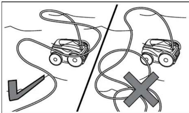
Diagram showing two car wheels connected by ropes, separated by a diagonal line and a cross symbol (no text or labels)Cleaner power cable may become tangled if correct procedure is not followed after each cleaning cycle.
natural_image
Illustration of hands assembling a mechanical component with a curved arrow indicating rotation (no text or symbols)igilnis
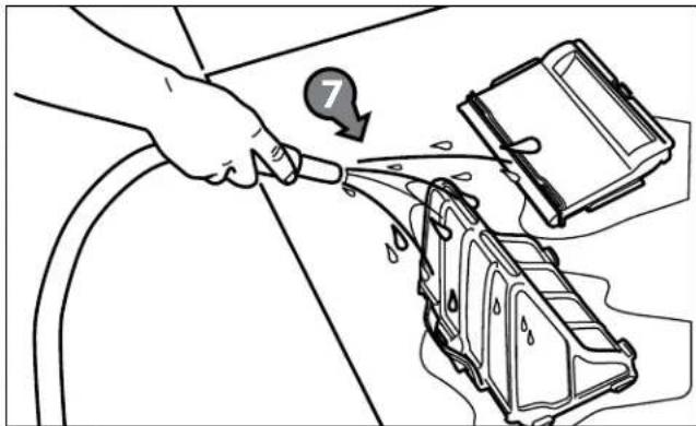
- Empty all debris from the filter canister, then rinse the canister, the filter support, and the cleaner under water or using a hose, as shown in Figure 28.
Tangling of the power cable can occur more frequently when operating the cleaner on the automatic timer 7-Day Programmed Cycle (9450/P945 and 9550/P955). Do not leave the cleaner unattended for prolonged periods and follow the procedure below to avoid excessive tangling.
Iningl
natural_image
Line drawing of a mechanical device with attached components (no text or symbols)- Unplug power to the cleaner at the control unit.
natural_image
Line drawing of a person using a small robot to interact with a curved line (no text or symbols)- Remove the cleaner from the pool and untangle all kinks and coils in the power cable starting at the cleaner head.
natural_image
Line drawing of a hand pouring liquid into a device with a lid nearby (no text or symbols)- Remove filter canister and rinse with clean water. Plug power cord back into control unit and store cleaner for next use.
linghshs
The cleaner is fitted with PVC brushes. There are "wear" indicators on the brushes (Figure 29). To maintain cleaner performance at its best you need to replace the brushes as soon as one of the wear indicators is reached (even if the blade wear is not even). It is recommended that you replace the brushes when the rubber is worn down to the top of the wear indicator (or every two years, whichever comes first).
text_image
ig ni s- Lift the cleaner to a vertical position so that the handle is up (Figure 30).
text_image
ig l n in igh si i n- Separate the edges of the brush and undo the tabs (Figure 31). Remove the worn brushes.
natural_image
Illustration of hands assembling or adjusting a mechanical component (no text or symbols visible)ignhshsh
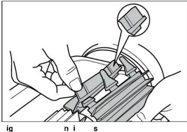
- To install a new brush, position the new brush on the roller with the spikes facing downwards (Figure 32).
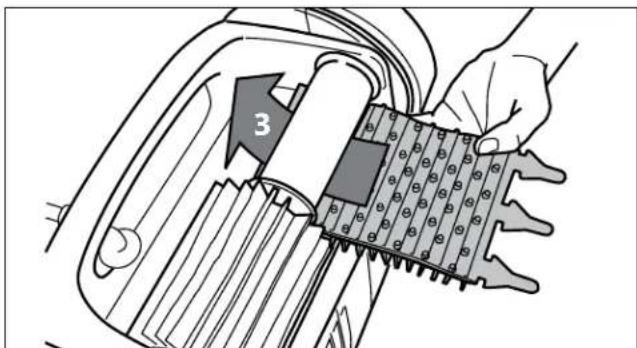
text_image
3ig nsllhsh
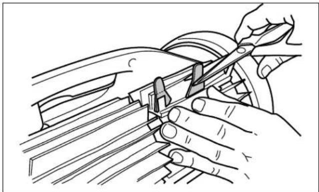
- Thread each tab into the slot provided and gently feed it through until the heel comes out at the other side of the slot (Figure 33).

natural_image
Illustration of hands assembling a mechanical component with a numbered arrow (no text or symbols present)igllshghEhl
- Use a pair of scissors to cut the tabs 3/4 inch from the heel so that they are no higher than the spikes (Figure 34).
natural_image
Line drawing of hands using a tool to adjust or install a mechanical component (no text or symbols present)igs
- Repeat this procedure to install the second brush.
linghis
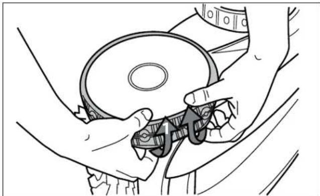
- Pull on the inside of the old tire to remove the tire lip from the wheel (Figure 35).
natural_image
Line drawing of hands operating a mechanical device with a circular component (no text or symbols)igllhlihhl
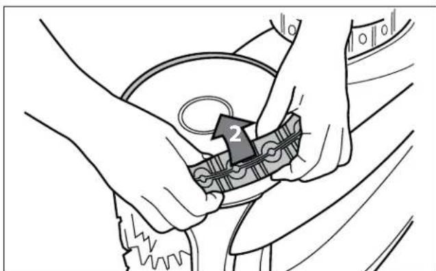
- Remove the old tire (Figure 36).
text_image
2ighli
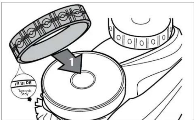
- To replace the tire, position the tire on the wheel making sure to orient the tire so that the word INSIDE is toward the body of the cleaner (Figure 37).
text_image
INSIDE Towards Body 1igilninin
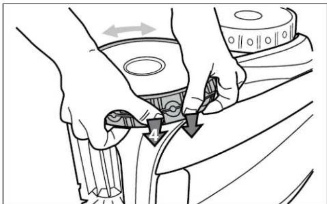
- Push one side of the tire on to the wheel and fit the rib of the tire in the groove of the wheel (Figure 38).
natural_image
Illustration of hands adjusting a car seatbelt with arrows indicating movement (no text or symbols)igshhiinInhhI
natural_image
Illustration of hands cleaning a circular object with a numbered label (2), no text or symbols presentignnihi
- Work the tire onto the wheel and verify the rib of the tire is positioned properly within the groove of the wheel (Figure 39).
i n s
The complete spare parts list and exploded view is available on the Polaris website at www.polarispool.com. In Canada, parts list and exploded view is available at www.polarispool.ca
text_image
3ighinnhhl
- Push and position the rib of the inner side of the tire in the groove of the wheel (Figure 40). If needed, turn the wheel gently to help with installation.
inlshing
sing h n i n E l sh ing l n
The Information LED ⓘ on the control unit flashes in a specific sequence to indicate one of three possible cleaner malfunctions.
| ninElshing | li n |
| LED flashes once with one second interval. | Unplug the floating cable from the control unit and reconnect.If the problem is not resolved through troubleshooting, contact Polaris Technical Support at (USA) 1-800-822-7933. |
| LED flashes twice with one second interval | Turn cleaner wheels to ensure they are not jammed.Check brushes for debris.Start a new cleaning cycle.If the problem persists, contact Polaris Technical Support at (USA) 1-800-822-7933. |
| LED flashes three times with one second interval | Check the pump axis for debris.Check propellor for debris.Clean the filter.Start a new cleaning cycle.If the problem persists, contact Polaris Technical Support at (USA) 1-800-822-7933. |
Information about your cleaner's current status and any relevant error condition is available through a troubleshooting status screen. To view this information:
- Remove cleaner from the pool and turn power off.

- Press and at the same time and hold for at least five (5) seconds.
The following cleaner operation messages are displayed consecutively for three (3) seconds:

text_image
96 34 lh s l n h s sin n Er: 10 s i l n h sh l s n 35 14 i in ing h s hAfter cycling through each message, control unit returns to current day and time display.
n l l sh ing
The following table lists some of the more common symptoms, causes and solutions encountered when using the 9450 Sport / P945 and the 9550 Sport / P955 cleaner.
| Islin | ||
| The flashing indicator lights (9350/P935) or error code on the display (9450/P945, 9550/P955) appear just after start (either pressing Power or Cycle button for less than 20 seconds).E If the flashing lights are accompanied by an error code on the display, refer to section 8.4 Control Unit Error Codes. | Floating cable may not be plugged into the control unit correctly. | Unplug floating cable from the control unit and reconnect. |
| Cleaner may not be fully submerged. | Remove cleaner from the pool and re-submerge, see Submerging the Cleaner. | |
| Cleaner may need to be reset and begin a new cycle. | Press power button OFF, then Cycle I or Cycle II to begin a new cycle. | |
| Propellor may be jammed and not turning correctly. | Contact Polaris Technical Support at (USA) 1-800-822-7933. | |
| Wheels may be jammed and not turning correctly. | Contact Polaris Technical Support at (USA) 1-800-822-7933. | |
| The flashing lights appear during the cleaning cycle. | Cleaner may be sucking air (lights will appear after 60 seconds air intake) | Remove cleaner from the pool and re-submerge, see Submerging the Cleaner. |
| The cleaner does not stay firmly on the pool bottom. | There is air in the appliance casing. | Submerge the cleaner following the procedure in Submerging the Cleaner. |
| The filter canister is full or dirty. Clean | the filter canister, see Cleaning the Filter Canister. | |
| The cleaner does not or no longer climbs the pool sides. | The filter canister is full or dirty. Clean | the filter canister, see Cleaning the Filter Canister. |
| Sides of pool are slippery or slimy. Although the water seems clear, microscopic algae, invisible to the human eye, are present in the pool. As a result the pool sides become slippery and prevent the cleaner from climbing. Check tires for wear and replace as necessary. | Do a shock chlorination treatment and slightly reduce the pH. DO NOT leave the cleaner in the pool during this treatment. | |
| On startup the cleaner does not move. | Not supplied with electricity. The outlet, | the control unit is connected to, is not supplying electrical power. Check that the outlet to which the control unit is connected is receiving electricity. |
| Unit is turned ON. | Check that you have started one (1) of the two (2) programs and check that the indicator for the selected program is lit. If the indicator light is not lit, turn the wheels then disconnect the control unit and wait at least 20 seconds before reconnecting. If the problem persists, contact Polaris Technical Support at (USA) 1-800-822-7933. | |
| Cable is tangling in the pool | Too much cable length in the water. | Do not unravel the entire cable length. Place only the required length of cable in the water and place the rest on the side of the pool. Follow the procedure in Cord Tangling to avoid and correct tangled cord. |
| The cleaner is not cleaning effectively. | The brushes have become smooth or the "wear" indicator shows. | Replace the brushes following the procedure in Replacing the Brushes. |
| Filter canister is full or dirty. | Clean the filter canister following the procedure in Cleaning the Filter Canister. | |
| Floating cable is excessively coiled or kinked. | Make sure the floating cable is spread out over the pool. Ensure the cable is not too tightly wrapped or coiled when storing. If the problem persists, lay the cable straight in the sun to relax it and remove kinks. | |
n I ni E s n
The control unit will display one of ten different error codes to indicate specific problems with either the control unit or mechanically with the cleaner.
• To remove an error code after troubleshooting, press any key and the control box turns off.
- If an error code is displayed and no key pressed, the screen goes into standby mode after 10 minutes of inactivity. Press any key to turn the screen back on.
- When an error is detected, programming for the control unit is temporarily suspended. The button is turned off.
Press and hold the PROG button to clear the error code and reactivate current programming.

| E | S | • lin |
| 1 | (1) Pump short-circuit. | • Check for any small debris or cable stopping brushes from turning freely. |
| 2 | (2) Right side traction motor short-circuit | • Check the connector pins in the power cable for corrosion or a bent pin. |
| 3 | (3) Left side traction motor short-circuit | • Turn each wheel one quarter turn in one direction repeatedly until rotation is smooth and not catching, then repeat turning wheel in the opposite direction until rotation is smooth.• If problem is not resolved through troubleshooting, contact Polaris Technical Support at (USA) 1-800-822-7933. |
| 4 | Pump motor overconsumption | • Check for small debris or hair in the fan.• Clean the filter canister. |
| 5 | (5) Right side drive motors overconsumption | • Check for any small debris or hair and that the cable is not caught, stopping brushes from turning freely. |
| 6 | (6) Left side drive motors overconsumption | • Turn each wheel one quarter turn in one direction repeatedly until rotation is smooth and not catching, then repeat turning wheel in the opposite direction until rotation is smooth. |
| 7 | (7) Cleaner floats on the surface. | • Turn cleaner power off, then submerge cleaner according to correct procedure. |
| 8 | (8) Cleaner is turned on and running out of water. | |
| 9 | NOT A CLEANER ERROR | • End of cycle status code. Cleaner function is normal. No action required. |
| 10 | Cleaner and control box communication error. | • Turn cleaner power off then back on to restart the program.• Check connection of the floating cable on the control box.• Check the connector pins in the power cable for corrosion or a bent pin.• If problem is not resolved through troubleshooting, contact Polaris Technical Support at (USA) 1-800-822-7933. |
Zodiac Pool Systems, Inc.
2620 Commerce Way, Vista, CA 92081
1.800.822.7933 | www.ZodiacPoolSystems.com
Zodiac Pool Systems Canada, Inc.
2115 South Service Road West, Unit 3
Oakville, Ontario • Canada L6L 5W2
1.888.647.4004 | www.ZodiacPoolSystems.ca
ZODIAC ^® is a registered trademark of Zodiac International, S.A.S.U., used under license. All trademarks referenced herein are the property of their respective owners.
©2013 Zodiac Pool Systems, Inc. H0392900 Rev C 1307
natural_image
Line drawing of a small robotic car with visible wheels and a textured body, labeled 'nlii' below (no other text or symbols)| ⚠️E n hing h h n h in l ning n in n n s i in his n l his s si n h is ll ns n l i i in l i n h is i i n hi h h ill ins ll h s hs l l i ns is n h n n s hs l l i n is s h in in s ssi n l ih s i i n in in l i n ins ll i n n in n n s h ll h ins i ns in his n l n ll ins ll i n n i n ill i h n |
 E i n l n i n in l in n n i ns n l i i is n h g n n is i s is l l l l i n s i ns is in l i i n l i i s ins ll l s ll s ig n sl ls in i l ss n i s i n ig n l l in i l ns is ni l g n n i n i n ssi nn l s is n i n ns ins ll i n l in n n i n is in ll n l s nsign s s n n l ins ll i n l ills i n in i nn l l g ni E i n l n i n in l in n n i ns n l i i is n h g n n is i s is l l l l i n s i ns is in l i i n l i i s ins ll l s ll s ig n sl ls in i l ss n i s i n ig n l l in i l ns is ni l g n n i n i n ssi nn l s is n i n ns ins ll i n l in n n i n is in ll n l s nsign s s n n l ins ll i n l ills i n in i nn l l g ni |
 E Es s ins l n ni n n is s i lii n i is in nl s is i i n nl l s ins l n is n isi s s ls l ls En l s ning n s l ls lig i l s ns l s n sin l n in i si i n nl is in l ins l in n ni in i s l sins ins n s n l s s gi n n s ins l s l sig s l s n is l sins ins n s El in ll i n ls is s ni ins ins sl n s l i l si n s sn ls ins l i n ins n l g n E Es s ins l n ni n n is s i lii n i is in nl s is i i n nl l s ins l n is n isi s s ls l ls En l s ning n s l ls lig i l s ns l s n sin l n in i si i n nl is in l ins l in n ni in i s l sins ins n s n l s s gi n n s ins l s l sig s l s n is l sins ins n s El in ll i n ls is s ni ins ins sl n s l i l si n s sn ls ins l i n ins n l g n |
l s i s
i n nsign si n s s i
s n iss n ss i ns i n n s g s l i n l is in s s l ss s
text_image
i n ss l g s ll gtext_image
ig i l in l snatural_image
Mechanical diagram showing a lever mechanism with arrows indicating motion (no text or symbols)iglll
s
natural_image
Line drawing of a mechanical device with a lever and adjustment arrow (no text or symbols)ignlinill
|
natural_image
Technical line drawing of a car interior showing structural components and wheel assembly (no text or labels)natural_image
Line drawing of a mechanical component with an arrow indicating direction (no text or symbols)igilignhi
natural_image
Line drawing of a handheld smart water heater with articulated arm and wheels (no text or symbols)ighinsInssl
n l
n hi
natural_image
Line drawing of a mechanical device with a scroll wheel and directional arrow (no text or symbols)igilhn
natural_image
Line drawing of a mechanical device with a button and cable, showing no text or symbolsignhllli
text_image
Diagram illustrating hand movement and approval steps with red X and green ✓ signstext_image
Diagram showing two methods of removing a pipe, with red 'X' indicating no change and green checkmark indicating confirmation.inninnn
⚠ EEE
natural_image
Two cartoon-style car illustrations on a road, one with a downward arrow and the other with a cross, connected by coiled cables (no text or symbols)h isi l I is in sl n
text_image
ig i l n l is in 1 2 I ign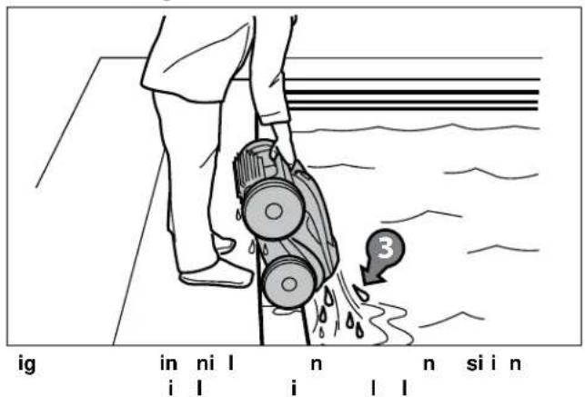
text_image
ig in ni l n n si n i l i l l
text_image
l n s l n l i lnatural_image
Line drawing of a person using a small robot to move a curved path (no text or symbols)ig I I I li n i n
natural_image
Line drawing of a lawn mower with three wheels and handle (no text or symbols)ig ng n s l h i
ingin
n
sln
text_image
CLOCK MON TUE WED THU FRI SAT SUN LUN MAR MER JEU VEN SAM DIM PROG s l s s l s in lign n is

natural_image
Line drawing of a hand operating a vacuum cleaner with a numbered component (no text or symbols)natural_image
Illustration of hands assembling a mechanical component with a curved arrow indicating rotation (no text or symbols)natural_image
Diagram showing two car wheels connected by ropes, one with a checkmark and the other with a cross (no text or symbols)natural_image
Line drawing of a mechanical device with attached sensors and buttons (no text or symbols)natural_image
Line drawing of a person using a small toy car to walk on a curved path (no text or symbols)natural_image
Line drawing showing a hand pouring liquid into a device with a lid nearby (no text or symbols)natural_image
Illustration of hands assembling or adjusting a mechanical component (no text or symbols visible)igilsnglsssss
natural_image
Mechanical assembly diagram showing hands assembling a component with a numbered arrow (no text or symbols present)ignslsnglsnshn
natural_image
Line drawing of hands using a tool to adjust or install a mechanical component (no text or symbols visible)iglsngls
natural_image
Line drawing of hands operating a mechanical device with a circular component (no text or symbols)ignlnsl
natural_image
Illustration of hands assembling a mechanical component with a numbered arrow (no text or symbols)igEnllns
text_image
INSIDE Towards Body 1iglignnnIn
natural_image
Line drawing of hands adjusting a car seatbelt with arrows indicating adjustment (no text or symbols)igInsI
natural_image
Illustration of hands cleaning a circular object with a numbered label (2), no text or symbols presentignnn
natural_image
Illustration of hands adjusting a circular object with a numbered arrow labeled '3' (no text or symbols beyond the number)igilnl
Zodiac Pool Systems, Inc.
2620 Commerce Way, Vista, CA 92081
1 800 822 7933 | www.ZodiacPoolSystems.com
Zodiac Pool Systems Canada, Inc.
2115 South Service Road West, Unit 3
Oakville (Ontario) • Canada L6L 5W2
1 888 647 4004 | www.ZodiacPoolSystems.ca
ZODIAC ^® is a registered trademark of Zodiac International, S.A.S.U., used under license. All trademarks referenced herein are the property of their respective owners.
natural_image
Line drawing of a toy car with wheels and a textured grip (no text or symbols)| ⚠️E n hing h h n h in l ning n in nn s i in his n l his ss i n h is li ns n l i in l i n h is i i n hi h h ill ins ll hs l l i ns is nh n ns hs l l i n is s h in in s ssi n l ih si i n in l i n ins ll in n in nn s h ll h ins ins in his n l n ll ins ll in n i n ill i h n |
| ⚠️EEE E in l n in in l in nn i ns n l i i is n h g n n is l s is l l i l i n s i ns is in l i i n l i i s ins ll l s ll s ig n sl ls in l ss n i s i n ig n l l in i l ns is ni l g n n i n i n ssi nn l s is n in ns ins ll in l in nn i n is in ll n l s nsign s s n n l ins ll in l ills in in i nn l l g nl |
| ⚠️E E l i s n s l in li i n ni in s sin ns n l s s ins l n ni n n is nl i ni ls lii insn sis is ins g s l is i in n s ins l l n s is n ls isi ss ls ls En s n is n ls isi ss ls l sl sn ll l n ni in s n sin l n in i si in nl ins l in n ni in i s is in s l sg l l l l | sins ins s n l ins l in l in in ss n s n l in lg n |
ni
i n ns i n s s g i i n s
Elin li in ls n is s l s sl n n l sin nn l in
E E
E E
E
Elin li in s s n is s l s i s l is in l sin s sn ls
natural_image
Technical line drawing of a mechanical device with directional arrows indicating motion (no text or symbols)igllillnis
natural_image
Line drawing of a mechanical device with a lever and adjustment arrow (no text or symbols)igslnsg
li
natural_image
Technical line drawing of a car interior showing structural components and wheel assembly (no text or labels)igllsslssl
Iss
natural_image
Line drawing of a mechanical component with an arrow indicating direction (no text or symbols)ignsllnili
text_image
ig I Ig n h I li i ns I gnatural_image
Line drawing of a handheld electric motor with attached sensor device (no text or symbols)iginsln
sinInin I I i
natural_image
Line drawing of a mechanical clamp or bracket with an arrow indicating rotation (no text or symbols)igllninlnli
natural_image
Line drawing of a mechanical device with a scroll wheel and directional arrow (no text or symbols)igl
n i n ls inis l i


natural_image
Line drawing of a mechanical device with a knob and cable, no text or symbols presentignllsinisli
text_image
Diagram illustrating two hand positions with red and green checkmarks indicating correct and incorrect states of a mechanical or electrical component.text_image
Diagram showing correct and incorrect ways to remove a pipe, with red 'X' indicating no change and green checkmark indicating confirmation.inin
E
text_image
Diagram comparing two car paths with a checkmark and cross symbol, likely illustrating a road safety or steering concept.I in I I is in (9550 Sport/P955 únicamente):
text_image
Diagram showing a person using a water pump with labeled component '3' and water droplets, likely illustrating a mechanical or hydraulic system.
ninin llii n
Inl
únicamente)
text_image
n nni g n is lnig n l
text_image
In I I I I I h Sig n si in ls l n l
natural_image
Line drawing of a lawn mower with wheels and handle (no text or symbols)inginl
lii
(9450 Sport/P945 y 9550 Sport/P955 únicamente)
natural_image
Line drawing of a hand operating a box labeled '3' on a wheeled cart (no text or symbols beyond label)natural_image
Illustration of hands assembling a battery pack with a directional arrow indicating rotation (no text or symbols)natural_image
Diagram showing two car wheels connected by ropes, separated by a diagonal line and a cross symbol (no text or labels)E
natural_image
Line drawing of a mechanical device with attached sensors and buttons (no text or symbols)natural_image
Line drawing of a person pulling a small toy car on a curved path (no text or symbols)natural_image
Line drawing of a hand pouring liquid into a device with a lid nearby (no text or symbols)natural_image
Illustration of hands assembling or adjusting a mechanical component (no text or symbols visible)iglsillslill
natural_image
Illustration of hands assembling or adjusting a mechanical component with a numbered arrow (no text or symbols present)igilsillssn
natural_image
Line drawing of hands using a tool to adjust or install a mechanical component (no text or symbols present)iglsills
natural_image
Line drawing of hands operating a CD or DVD disc assembly (no text or symbols)ig i ln i i n i l
- Saque el neum tico vie o (Figura 36).
natural_image
Illustration of hands assembling a mechanical component with a numbered arrow (no text or symbols)ig Inii
text_image
INSIDE Towards Body 1igininlsniss
natural_image
Illustration of hands adjusting a car seatbelt with arrows indicating movement (no text or symbols)igElninssiinl
natural_image
Illustration of hands cleaning a circular object with a numbered label (2), no text or symbols presentigEinnllni
natural_image
Illustration of hands adjusting a circular object with a numbered arrow labeled '3' (no text or symbols beyond the number)ig
Zodiac Pool Systems, Inc.
2620 Commerce Way, Vista, CA 92081
1.800.822.7933 | www.ZodiacPoolSystems.com
Zodiac Pool Systems Canada, Inc.
2115 South Service Road West, Unit 3
Oakville, Ontario • Canada L6L 5W2
1.888.647.4004 | www.ZodiacPoolSystems.ca
ZODIAC ^® is a registered trademark of Zodiac International, S.A.S.U., used under license. All trademarks referenced herein are the property of their respective owners.
©2013 Zodiac Pool Systems, Inc. H0392900 Rev C 130