
1035 - Multimeter PeakTech - Free user manual and instructions
Find the device manual for free 1035 PeakTech in PDF.
| Brand | PeakTech |
| Model | 1035 |
| Type | Digital Multimeter |
| Display | LCD 27 mm, 3 ½ digits (max 1999) |
| Dimensions (LxWxH) | 70 x 150 x 50 mm (case included) |
| Weight | 260 g (case included) |
| Power Supply | 1 x 9 V battery (NEDA 1604, 6F22) |
| Measurement Functions | DC/AC voltage, DC current, resistance, diode test, battery test |
| DC Voltage Ranges | 200 mV, 2000 mV, 20 V, 200 V, 600 V |
| AC Voltage Ranges | 200 V, 600 V |
| DC Current Ranges | 2000 µA, 20 mA, 200 mA, 10 A |
| Resistance Ranges | 200 Ω, 2000 Ω, 20 kΩ, 200 kΩ, 2000 kΩ |
| Overvoltage Category | CAT III 600 V |
| Pollution Degree | 2 |
| Special Functions | Data Hold, backlight, battery test |
| Overload Protection | Fuses 0.2 A/600 V (µA/mA) and 10 A/600 V (10 A) |
| Maintenance | Clean with a damp, lint-free cloth |
| Repairability | Repair by qualified service technician only |
| Accessories Included | Carrying case, test leads, battery, manual |
| Operating Temperature | 0 °C to 50 °C |
| Storage Temperature | -20 °C to 60 °C |
Frequently Asked Questions - 1035 PeakTech
User questions about 1035 PeakTech
0 question about this device. Answer the ones you know or ask your own.
Ask a new question about this device
Download the instructions for your Multimeter in PDF format for free! Find your manual 1035 - PeakTech and take your electronic device back in hand. On this page are published all the documents necessary for the use of your device. 1035 by PeakTech.
USER MANUAL 1035 PeakTech
natural_image
Simple line drawing of a trash bin with diagonal lines crossing through it (no text or symbols)PeakTech ^® 01/2019 Th/Pt/Po./Mi
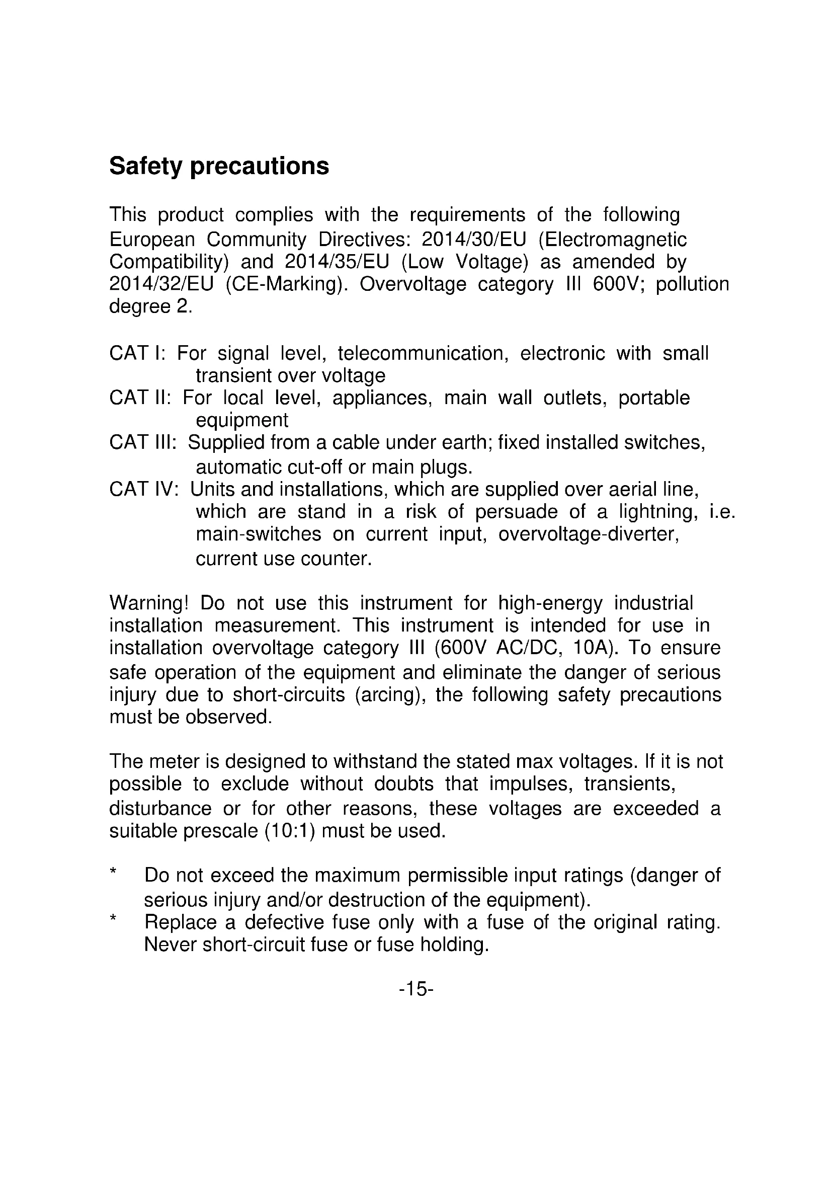
Safety precautions
This product complies with the requirements of the following European Community Directives: 2014/30/EU (Electromagnetic Compatibility) and 2014/35/EU (Low Voltage) as amended by 2014/32/EU (CE-Marking). Overvoltage category III 600V; pollution degree 2.
CAT I: For signal level, telecommunication, electronic with small transient over voltage
CAT II: For local level, appliances, main wall outlets, portable equipment
CAT III: Supplied from a cable under earth; fixed installed switches, automatic cut-off or main plugs.
CAT IV: Units and installations, which are supplied over aerial line, which are stand in a risk of persuade of a lightning, i.e. main-switches on current input, overvoltage-diverter, current use counter.
Warning! Do not use this instrument for high-energy industrial installation measurement. This instrument is intended for use in installation overvoltage category III (600V AC/DC, 10A). To ensure safe operation of the equipment and eliminate the danger of serious injury due to short-circuits (arcing), the following safety precautions must be observed.
The meter is designed to withstand the stated max voltages. If it is not possible to exclude without doubts that impulses, transients, disturbance or for other reasons, these voltages are exceeded a suitable prescale (10:1) must be used.
* Do not exceed the maximum permissible input ratings (danger of serious injury and/or destruction of the equipment).
* Replace a defective fuse only with a fuse of the original rating. Never short-circuit fuse or fuse holding.
* Disconnect test leads or probe from the measuring circuit before switching modes or functions.
* Do not conduct voltage measurements with the test leads connected to the mA/A- and COM-terminal of the equipment.
* To avoid electric shock, disconnect power to the unit under test and discharge all capacitors before taking any resistance measurements.
* Do not conduct current measurements with the leads connected to the V/Ω-terminals of the equipment.
* Check test leads and probes for faulty insulation or bare wires before connection to the equipment.
* To avoid electric shock, do not operate this product in wet or damp conditions. Conduct measuring works only in dry clothing and rubber shoes, i. e. on isolating mats.
* Never touch the tips of the test leads or probe.
* Comply with the warning labels and other info on the equipment.
* Always start with the highest measuring range when measuring unknown values.
* Do not subject the equipment to direct sunlight or extreme temperatures, humidity or dampness.
* Do not subject the equipment to shocks or strong vibrations.
* Do not operate the equipment near strong magnetic fields (motors, transformers etc.).
* Keep hot soldering irons or guns away from the equipment.
* Allow the equipment to stabilize at room temperature before taking up measurement (important for exact measurements).
* Do not input values over the maximum range of each measurement to avoid damages of the meter.
* Do not turn the rotary function switch during voltage or current measurement, otherwise the meter could be damaged.
* Use caution when working with voltages above 35V DC or 25V AC. These Voltages pose shock hazard.
* Replace the battery as soon as the battery indicator “BAT” appears. With a low battery, the meter might produce false reading that can lead to electric shock and personal injury.
* Fetch out the battery when the meter will not be used for long period.
* Periodically wipe the cabinet with a damp cloth and mid detergent. Do not use abrasives or solvents.
* The meter is suitable for indoor use only
* Do not operate the meter before the cabinet has been closed and screwed safely as terminal can carry voltage.
* Do not store the meter in a place of explosive, inflammable substances.
* Measuring instruments don't belong to children hands.
Cleaning the cabinet
Clean only with a damp, soft cloth and a commercially available mild household cleanser. Ensure that no water gets inside the equipment to prevent possible shorts and damage to the equipment.
1. Introduction
This instrument is a compact, rugged, battery operated, handheld 3 12 digit multimeter for measuring DC and AC voltage, DC current, resistance and diode. The dual-slope A/D converter uses C-MOS technology for auto-zeroing, polarity selection and overrange indication. Full overload protection is provided.
2. Features
* Single 20 positions easy to use rotary switch for function and range selection
* 27 mm high contrast LCD
* Backlight
* Automatic overrange indication with the "OL" displayed
* Automatic polarity indication on DC ranges
* Diode testing with 1 mA fixed current
* Hold-function
* Battery test
CAUTION!
Note on using the supplied safety test leads according the IEC /
EN 61010-031:2008:
Measurements in the field of overvoltage category CAT I or CAT II can be performed with test leads without sleeves with a maximum of up to 18mm long, touchable metallic probe, whereas for measurements in the field of overvoltage category CAT III or CAT IV test leads with put on sleeves, printed with CAT III and CAT IV must be used, and therefore the touchable and conductive part of the probes have only max. 4mm of length.
3. Specifications
Accuracies are: (% of reading + no. of digits) guaranteed for 1 year, 23^ C ± 5°C, less than 75% R.H.
DC Voltage
| Range | Accuracy | Resolution |
| 200 mV | ± 0.5 % + 2 digit | 100 μV |
| 2000 mV | 1 mV | |
| 20 V | 10 mV | |
| 200 V | 100 mV | |
| 600 V | 1 V |
Input Impedance: > 1 MΩ on all ranges
Overload protection: 600 V DC or peak AC rms on all ranges, in 200 mV range 220 V _rms
AC Voltage
| Range | Accuracy | Resolution |
| 200 V | ± 1.2 % + 10 digit | 100 mV |
| 600 V | 1 V |
Input Impedance: > 1MΩ on all ranges
Frequency range: 45 Hz to 450 Hz
Overload protection: 600 V DC or AC rms in all ranges
Indication: Average (rms of sine wave)
DC Current
| Range | Accuracy | Resolution |
| 2000 μA | ± 1,0 % + 2 digit | 1 μA |
| 20 mA | 10 μA | |
| 200 mA | ± 1,2 % + 2 digit | 100 μA |
| 10 A | ± 2,0 % + 2 digit | 10 mA |
Overload protection: μA/mA-ranges: 0,2 A/600 V fuse
10A-ranges: 10A/600V fuse
maximum input current: 10 A
Resistance
| Range | Accuracy | Resolution |
| 200 Ω | ± 0.8 % + 2 digit | 0.1 Ω |
| 2000 Ω | 1 Ω | |
| 20 kΩ | 10 Ω | |
| 200 kΩ | 100 Ω | |
| 2000 kΩ | ± 1,0 % + 2 digit | 1 kΩ |
Max. open circuit: under 2,8 V
Overload protection: 220 V _rms in all ranges (max. 15 sec.)
Diode Test
| Range | Description | Test Conditions |
 | Display read approx. forward voltage of diode | Forward DC current 1 mA.Reversed DC voltage approx. 2,8 V. |
4. General Characteristics
Display 27 mm LCD display, 1999 counts
(3 12 digits) with automatic polarity indication
Overrange indication "OL" Figure only in the display
common mode voltage 600 V max.
Reading rate time 2-3 readings per sec. (approx.)
Temperature for
guaranteed accuracy 23^ C ± 5^ C
Operating Temperature 0°C...50°C (32°F....122°F)
Storage Temperature -20°C...60°C (-4°F...140°F)
Power Supply One 9 Volt battery (NEDA 1604, 6F22
Type or equivalent)
Low Battery Indication
"LO BAT" or "BAT" on the left of the display
Size (WxHxD)
70 x 150 x 50 mm with holster
Weight 260 g with holster
Accessories
carrying case, test leads, battery and operation manual
5. Operation
5.1. Front Panel Description
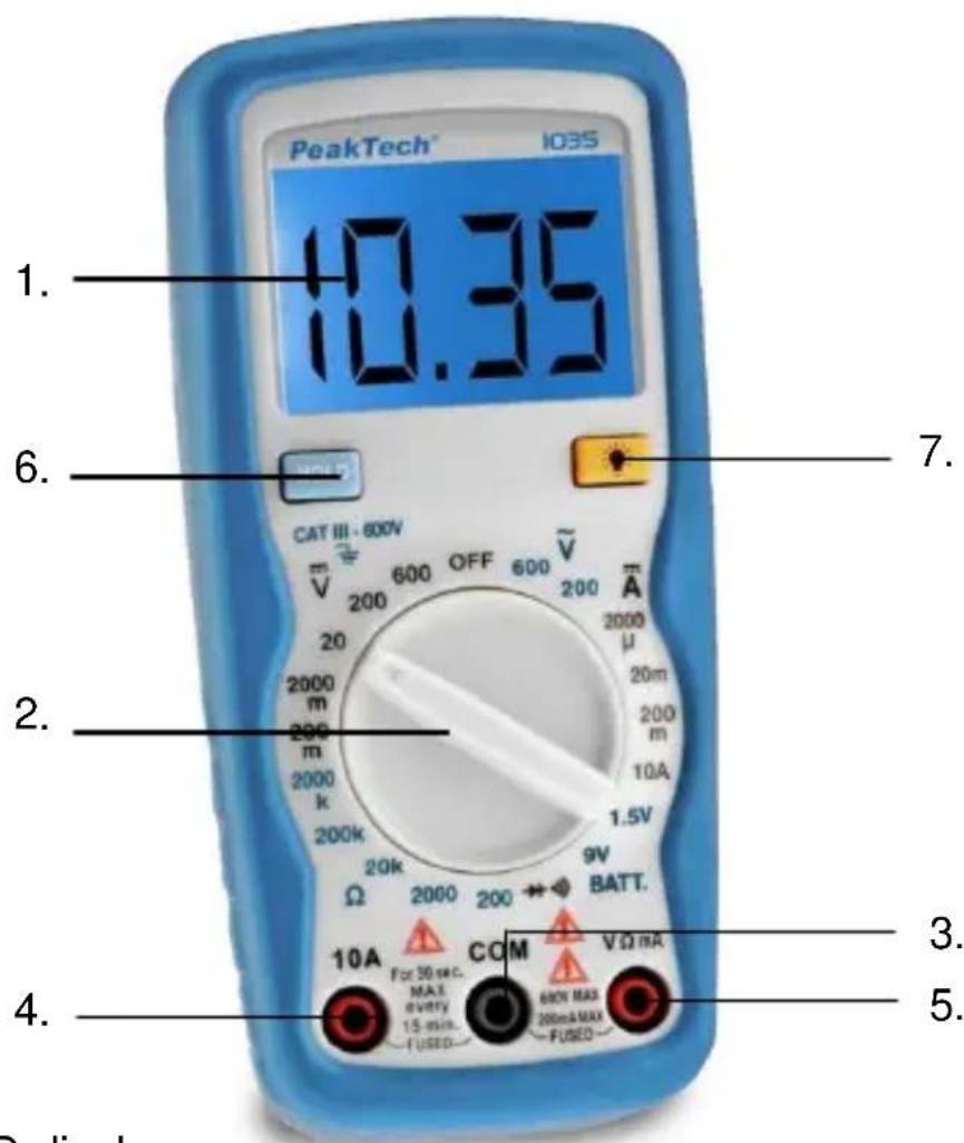
text_image
PeakTech™ 103S 1. 10.35 6. 7. CAT III - 800V 200 600 OFF 600 V̅ 200 μA 2000 m 2000 m 2000 k 200k 1.5V Ω 2000 200 BATT. 10A For 30 sec. MAX every 15 min. COM V Ω mA FUSED 60N MAX 200mA MAX FUSED 4. 5. Display- LCD-display
- Function switch
- COM-input jack
- 10 A-input jack
- V/Ω/mA-input jack
- Data-Hold
- Backlight
5.2. Preliminary Note
- To check the 9 V battery please switch on the DMM. If the battery is weak, a "LO BAT" or "BAT" sign will appear on the left of Display. If this does not appear on the display proceed as below. See "Maintenance" if the battery has to be replaced.
- The warning sign next to the test leads jack is for warning that the input voltage or current should not exceed the indicated values. This is to prevent damage to the internal circuitry.
- The function switch should be set to the range which you want to test before operation.
5.3. DC Voltage Measurement
- Connect the black test lead to the COM jack and the red test lead to the V/Ω/ mA- jack.
- Set the function switch to the DC V range to be used and connect the test leads across the source or load under measurement.
Note:
- If the voltage range is not known beforehand set the function switch to the highest range and work down.
- When only the figure "OL" is displayed, overrange is being indicated and the Function switch must be set to a higher range.
- CAUTION: Do not apply more than 600 V to the input. Indication is possible at higher voltages but there is danger of damaging the internal circuitry.
- Use extreme caution to avoid contact with high tension circuits when measuring high voltage.
5.4. AC Voltage Measurement
- Connect the black test lead to the COM jack and the red test lead to the V/Ω/ mA-jack.
- Set function switch to the AC V range to be used and connect the test leads across the source or load under measurement.
Note:
- If the voltage range is not known beforehand set the function switch to the highest range and work down.
- Caution: Do not apply more than 600 V rms to the input. Indication is possible at higher voltages but there is danger of damaging the internal circuitry.
- Use extreme caution to avoid contact with high tension circuits when measuring high voltage.
5.5. DC Current Measurement
- Connect the black test lead to the COM jack and the red test lead to the V/Ω/ mA-jack for a max. of 200 mA. For a maximum of 10 A, move the red test lead to the 10 A jack.
Set the function switch to the DC A range to be used and connect the test leads in series with the load under measurement.
Note:
- If the current range is not known beforehand, set the FUNCTION switch to the highest range and work down.
-
When only the figure "OL" is displayed overrange is being indicated and the FUNCTION switch must be set at higher range.
-
Caution: The maximum input current is 200 mA, or 10 A depending upon the jack used. Excessive current will blow the fuse which must be replaced.
- Replace the blown fuse only with a fuse with the same ratings and dimensions.
5.6. Resistance Measurement
- Connect the black test lead to the COM jack and the red test lead to the V/Ω/-mA-jack. (Note: The polarity of the red test lead is "+"
- Set the function switch to the range to be used and connect the test leads across the resistance under measurement.
Note:
- If the resistance value being measured exceeds the maximum voltage of the range selected, an over-range indication will be displayed "OL". Select a higher range. For resistance approx. 1 MΩ and above, the meter may take a few seconds to stabilize. This is normal for high resistance readings.
- When the input is not connected, i. e. at open circuit, the figure "OL" will be displayed for the overrange condition.
- When checking in-circuit resistance, be sure the circuit under test has all power removed and that all capacitors are fully discharged.
5.7. Diode Measurement
- Connect the black test lead to the COM jack and the red test lead to the V/Ω/-mA-jack. (Note: the polarity of the red test lead is "+"
- Set the function switch to the -range an connect the test leads across the diode under measurement.
Note:
- When the input is not connected, i. e. at open circuit, the figure "OL" will be displayed for the overrange condition.
- There is 1 mA current flow through the device under test
- The meter displays the forward voltage drop in millivolts, and overload when the diode is reversed.
5.8. Battery test function
With this function you can test batteries with a load in form of a resistance, resulting in a more accurate assessment of the battery power as in the pure tension test.
This measurement function is not suitable for testing of button cells, because they are not designed for high load.
Load ranges
1,5 V/13,4 Ω for AAA/UM4 & AA/UM3 batteries
9 V/1,4 kΩ for 9V (NEDA 1604, 6F22, 006P) batteries
WARNING!
If not handled carefully, batteries and accumulators can cause by sparks or even an explosion of the battery through a short-circuit. Make sure that the battery poles are never shorted by metallic items.
- Connect the black test lead into the "COM" socked and the red test lead into the "V/Ω/mA" socket.
- Turn the rotary switch to the battery test position 1,5 V or 9 V range, which the nominal voltage of the test battery meets.
- Connect both test probes to the battery to be measured.
6. Maintenance
Your digital multimeter is a precision electronic devise. Do not tamper with the circuitry. To avoid damage:
a) Never connect more than 600 V DC or AC rms
b) Never connect a source of voltage with function switch on position and - position.
c) Never operate the DMM unless the battery cover is in place and fully closed.
d) Battery and/or fuse replacement should only be done after the test leads have been disconnected and power is off.
6.1. Battery Replacement
Note the condition of the 9-V-battery using the procedure described above. If the battery needs to be replaced, open the back cover, remove the spent battery and replace with a battery of the same type.
Batteries, which are used up dispose duly. Used up batteries are hazardous and must be given in the for this being supposed collective container.
6.2. Statutory Notification about the Battery Regulations
The delivery of many devices includes batteries, which for example serve to operate the remote control. There also could be batteries or accumulators built into the device itself. In connection with the sale of these batteries or accumulators, we are obliged under the Battery Regulations to notify our customers of the following:
Please dispose of old batteries at a council collection point or return them to a local shop at no cost. The disposal in domestic refuse is strictly forbidden according to the Battery Regulations. You can return used batteries obtained from us at no charge at the address on the last side in this manual or by posting with sufficient stamps.
natural_image
Simple line drawing of a trash bin with no text or symbolsBatteries, which contain harmful substances, are marked with the symbol of a crossed-out waste bin, similar to the illustration shown left. Under the waste bin symbol is the chemical symbol for the harmful substance, e.g. „Cd“ for cadmium, „Pb“ stands for lead and „Hg“ for mercury.
You can obtain further information about the Battery Regulations from the Bundesministerium für Umwelt, Naturschutz und
Reaktorsicherheit (Federal Ministry of Environment, Nature Conservation and Reactor Safety).
6.3. Fuse Replacement
Should the fuse need replacement, use only fuses identical in physical size to the original (0,2A/600V ; 10A/250V).
All rights, also for translation, reprinting and copy of this manual or parts are reserved. Reproductions of all kinds (photocopy, microfilm or other) only by written permission of the publisher.
This manual is according the latest technical knowing. Technical alterations reserved.
We herewith confirm that the units are calibrated by the factory according to the specifications as per the technical specifications.
We recommend to calibrate the unit again, after 1 year.
© PeakTech ^® 01/2019 Th/Pt/Po./Mi
natural_image
Simple line drawing of a trash bin with diagonal lines crossing it, no text or symbols present.PeakTech ^® 01/2019 Th/Pt/Po./Mi
natural_image
Simple line drawing of a trash bin with diagonal lines crossing through it (no text or symbols)PeakTech ^® 01/2019 Th/Pt/Po./Mi
natural_image
Simple line drawing of a trash bin with diagonal lines crossing through it, no text or symbols present.PeakTech ^® 01/2019 Th/Pt/Po./Mi