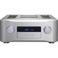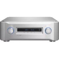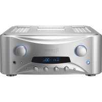
Grandioso F1 - Receiver Esoteric - Free user manual and instructions
Find the device manual for free Grandioso F1 Esoteric in PDF.


User questions about Grandioso F1 Esoteric
0 question about this device. Answer the ones you know or ask your own.
Ask a new question about this device
Download the instructions for your Receiver in PDF format for free! Find your manual Grandioso F1 - Esoteric and take your electronic device back in hand. On this page are published all the documents necessary for the use of your device. Grandioso F1 by Esoteric.
USER MANUAL Grandioso F1 Esoteric
The lightning flash with arrowhead symbol, within an equilateral triangle, is intended to alert the user to the presence of uninsulated "dangerous voltage" within the product's enclosure that may be of sufficient magnitude to constitute a risk of electric shock to persons.

The exclamation point within an equilateral triangle is intended to alert the user to the presence of important operating and maintenance (servicing) instructions in the literature accompanying the appliance.
WARNING: TO PREVENT FIRE OR SHOCK HAZARD, DO NOT EXPOSE THIS APPLIANCE TO RAIN OR MOISTURE.
CAUTION
●DO NOT REMOVE THE EXTERNAL CASES OR CABINETS TO EXPOSE THE ELECTRONICS. NO USER SERVICEABLE PARTS ARE INSIDE.
- IF YOU ARE EXPERIENCING PROBLEMS WITH THIS PRODUCT, CONTACT THE STORE WHERE YOU PURCHASED THE UNIT FOR A SERVICE REFERRAL. DO NOT USE THE PRODUCT UNTIL IT HAS BEEN REPAIRED.
- USE OF CONTROLS OR ADJUSTMENTS OR PERFORMANCE OF PROCEDURES OTHER THAN THOSE SPECIFIED HEREIN MAY RESULT IN HAZARDOUS RADIATION EXPOSURE.
IN USA/CANADA, USE ONLY ON 120 V SUPPLY.
Model for USA
This equipment has been tested and found to comply with the limits for a Class B digital device, pursuant to Part 15 of the FCC Rules. These limits are designed to provide reasonable protection against harmful interference in a residential installation. This equipment generates, uses, and can radiate radio frequency energy and, if not installed and used in accordance with the instructions, may cause harmful interference to radio communications. However, there is no guarantee that interference will not occur in a particular installation. If this equipment does cause harmful interference to radio or television reception, which can be determined by turning the equipment off and on, the user is encouraged to try to correct the interference by one or more of the following measures:
- Reorient or relocate the equipment and/or the receiving antenna.
- Increase the separation between the equipment and receiver.
- Connect the equipment into an outlet on a circuit different from that to which the receiver is connected.
- Consult the dealer or an experienced radio/TV technician for help.
Model for Canada
Industry Canada's Compliance Statement:
This Class B digital apparatus complies with Canadian ICES-003.
Model for Europe

This product complies with the European Directives request, and the other Commission Regulations.
CAUTION
Changes or modifications not expressly approved by the party responsible for compliance could void the user's authority to operate the equipment.
- The information in the following table is only applicable to products for sale in the People's Republic of China.
● The products sold in the European area are manufactured in accordance with the European RoHS Directive.

产品有毒有害物质或元素的名称及含量
1) Read these instructions.
2) Keep these instructions.
3) Heed all warnings.
4) Follow all instructions.
5) Do not use this apparatus near water.
6) Clean only with dry cloth.
12) Use only with the cart, stand, tripod, bracket, or table specified by the manufacturer, or sold with the apparatus. When a cart is used, use caution when moving the cart/ apparatus combination to avoid injury from tip-over.
7) Do not block any ventilation openings. Install in accordance with the manufacturer's instructions.
8) Do not install near any heat sources such as radiators, heat registers, stoves, or other apparatus (including amplifiers) that produce heat.
9) Do not defeat the safety purpose of the polarized or grounding-type plug. A polarized plug has two blades with one wider than the other. A grounding type plug has two blades and a third grounding prong. The wide blade or the third prong are provided for your safety. If the provided plug does not fit into your outlet, consult an electrician for replacement of the obsolete outlet.
10) Protect the power cord from being walked on or pinched particularly at plugs, convenience receptacles, and the point where they exit from the apparatus.
11) Only use attachments/accessories specified by the manufacturer.

13) Unplug this apparatus during lightning storms or when unused for long periods of time.
14) Refer all servicing to qualified service personnel. Servicing is required when the apparatus has been damaged in any way, such as power-supply cord or plug is damaged, liquid has been spilled or objects have fallen into the apparatus, the apparatus has been exposed to rain or moisture, does not operate normally, or has been dropped.
●The apparatus draws nominal non-operating power from the AC outlet with its POWER or STANDBY/ON switch not in the ON position.
- The mains plug is used as the disconnect device; the disconnect device shall remain readily operable.
●Caution should be taken when using earphones or headphones with the product because excessive sound pressure (volume) from earphones or headphones can cause hearing loss.
WARNING
Products with Class I construction are equipped with a power supply cord that has a grounding plug. The cord of such a product must be plugged into an AC outlet that has a protective grounding connection.
CAUTION
- Do not expose this apparatus to drips or splashes.
- Do not place any objects filled with liquids, such as vases, on the apparatus.
- Do not install this apparatus in a confined space such as a book case or similar unit.
●The apparatus should be located close enough to the AC outlet so that you can easily reach the power cord plug at any time. - If the product uses batteries (including a battery pack or installed batteries), they should not be exposed to sunshine, fire or excessive heat.
- CAUTION for products that use replaceable lithium batteries: there is danger of explosion if a battery is replaced with an incorrect type of battery. Replace only with the same or equivalent type.

Precautions concerning batteries
Misuse of batteries could cause them to rupture or leak leading to fire, injury or the staining of nearby things. Please read and observe the following precautions carefully.
- Be sure to insert the batteries with correct positive (⊕) and negative (⊖) orientations.
- Use batteries of the same type. Never use different types of batteries together.
- If the remote control is not used for a long time (more than a month), remove the batteries to prevent them from leaking.
- If the batteries leak, wipe away the leakage inside the battery compartment and replace the batteries with new ones.
- Do not use batteries of types other than those specified. Do not mix new batteries with old ones or use different types of batteries together.
- Do not heat or disassemble batteries. Never throw batteries into fire or water.
- Do not carry or store batteries with other metallic objects. The batteries could short circuit, leak or explode.
- Never recharge a battery unless it is confirmed to be a rechargeable type.
For European Customers
Disposal of electrical and electronic equipment and batteries and/or accumulators
a) All electrical/electronic equipment and waste batteries/accumulators should be disposed of separately from the municipal waste stream via collection facilities designated by the government or local authorities.
b) By disposing of electrical/electronic equipment and waste batteries/accumulators correctly, you will help save valuable resources and prevent any potential negative effects on human health and the environment.
c) Improper disposal of waste electrical/electronic equipment and batteries/accumulators can have serious effects on the environment and human health because of the presence of hazardous substances in the equipment.
d) The Waste Electrical and Electronic Equipment (WEEE) symbols, which show wheeled bins that have been crossed out, indicate that electrical/electronic equipment and batteries/accumulators must be collected and disposed of separately from household waste.
If a battery or accumulator contains more than the specified values of lead (Pb), mercury (Hg), and/or cadmium (Cd) as defined in the Battery Directive (2006/66/EC), then the chemical symbols for those elements will be indicated beneath the WEEE symbol.
e) Return and collection systems are available to end users. For more detailed information about the disposal of old electrical/electronic equipment and waste batteries/accumulators, please contact your city office, waste disposal service or the shop where you purchased the equipment.
Contents
Thank you for purchasing this Esoteric product.
Read this manual carefully to get the best performance from this product. After reading it, keep it in a safe place with the warranty card for future reference.
IMPORTANT SAFETY INSTRUCTIONS 3
Before use....6
Connections....8
Connecting speakers .... 10
Connecting with a Grandioso K1....12
Notes about the protection circuits....12
Notes about the remote control ....13
Names and functions of parts (main unit) 14
Using headphones 15
Names and functions of parts (remote control)....16
Basic operation....17
Settings 20
Settings Menu 1....21
Settings Menu 2....22
Settings Menu 3....23
Restoring factory settings....24
Troubleshooting....24
Specifications....25
Dimensional drawings....26
Before use
What's in the box
Check to be sure the box includes all the supplied accessories shown below. Please contact the store where you purchased this unit if any of these accessories are missing or have been damaged during transportation.
Power cord × 1
Remote control (RC-1315) × 1
Batteries for remote control (AAA) × 2
Felt pads × 4
Owner's manual (this document) × 1
Warranty card × 1
Note about pinpoint feet
High-precision metal pinpoint feet are attached firmly to the bottom plate of this unit.

text_image
Chassis Pinpoint foot (metal) Foot-stand (metal) Screws that attach foot-standThe stands for these feet are loose, but when the unit is placed in position, it is supported by these pinpoint feet, which will effectively disperse vibrations.
- Apply the included felt pads to the bottoms of the foot-stands to avoid scratching the surface where the unit is placed.
Precautions for use
- Place the unit in a stable location near the audio system that you will use with it.
- Do not install this unit in a location that could become hot. This includes places that are exposed to direct sunlight or near a radiator, heater, stove or other heating equipment. Moreover, do not place it on top of another amplifier or equipment that generates heat.
- Avoid locations that are subject to vibrations or exposed to excessive dust, cold or moisture.
- In order to enable good heat dissipation, leave at least 20 cm (8") between this unit and walls and other equipment when installing it. If you put it in a rack, take precautions to prevent overheating by leaving at least 20 cm (8") open above the top of the unit and at least 10 cm (4") open behind the unit.
Failure to provide these gaps could cause heat to build up inside and result in fire. - Do not install the unit face up or on its side.
- Do not place anything, not even CDs, CD-Rs, LP records or cassette tapes, on top of the unit. Do not put cloth on top of the unit or place it on top of bedding or thick carpet. Doing so could cause it to overheat or damage it.
- Do not move the unit during use.
- Be careful to avoid injury when moving the unit due to its weight. Have someone help you move it if necessary.
- The voltage supplied to the unit should match the voltage printed on the rear panel. If you are in any doubt regarding this matter, consult an electrician.
- Do not open the body of the unit as this might result in damage to the circuitry or cause electric shock. If a foreign object should get into the unit, contact your dealer.
- When removing the power plug from the wall outlet, always pull directly on the plug; never yank on the cord.
Maintenance
Use a soft dry cloth to wipe the surface of the unit clean.
For stubborn smudges, use a damp cloth that has been thoroughly wrung out to remove excess moisture.

For safety, disconnect the power plug from the outlet before cleaning.
● Never spray liquid directly on this unit.
- Do not use chemically-treated wipes, thinner or similar substances because they could damage the surface of the unit.
- Avoid allowing rubber or plastic materials to touch the unit for long periods of time because they could damage the cabinet.

Precautions when making connections
● After completing all other connections, plug the power plug into a power outlet.
- Read the owner's manuals of all devices that will be connected, and follow their instructions.
- Do not bundle connecting cables with power cords. Doing so could cause noise.
flowchart
graph TD
    A["Record player"] --> B["Grandioso K1"]
    B --> C["When using a Grandioso K1"]
    C --> D["Set the analog output (AOUT) of the Grandioso K1 to ESLA."]
    D --> E["Super Audio CD player, etc."]
    E --> F["Audio outputs (AUDIO OUT, etc.)"]
    E --> G["Super Audio CD player, tuner, etc."]
    F --> H["XLR pin assignment 1. COMMON 2. HOT (+) 3. COLD (−)"]
    G --> I["XL R audio cables"]
    G --> J["RCA audio cables"]
    G --> K["A"]
    G --> L["E"]
    style A fill:#f9f,stroke:#333
    style B fill:#ccf,stroke:#333
    style C fill:#cfc,stroke:#333
    style D fill:#fcc,stroke:#333
    style E fill:#ffc,stroke:#333
    style F fill:#cfc,stroke:#333
    style G fill:#cfc,stroke:#333
    style H fill:#fff,stroke:#333
    style I fill:#fff,stroke:#333
    style J fill:#fff,stroke:#333
    style K fill:#fff,stroke:#333
    style L fill:#fff,stroke:#333
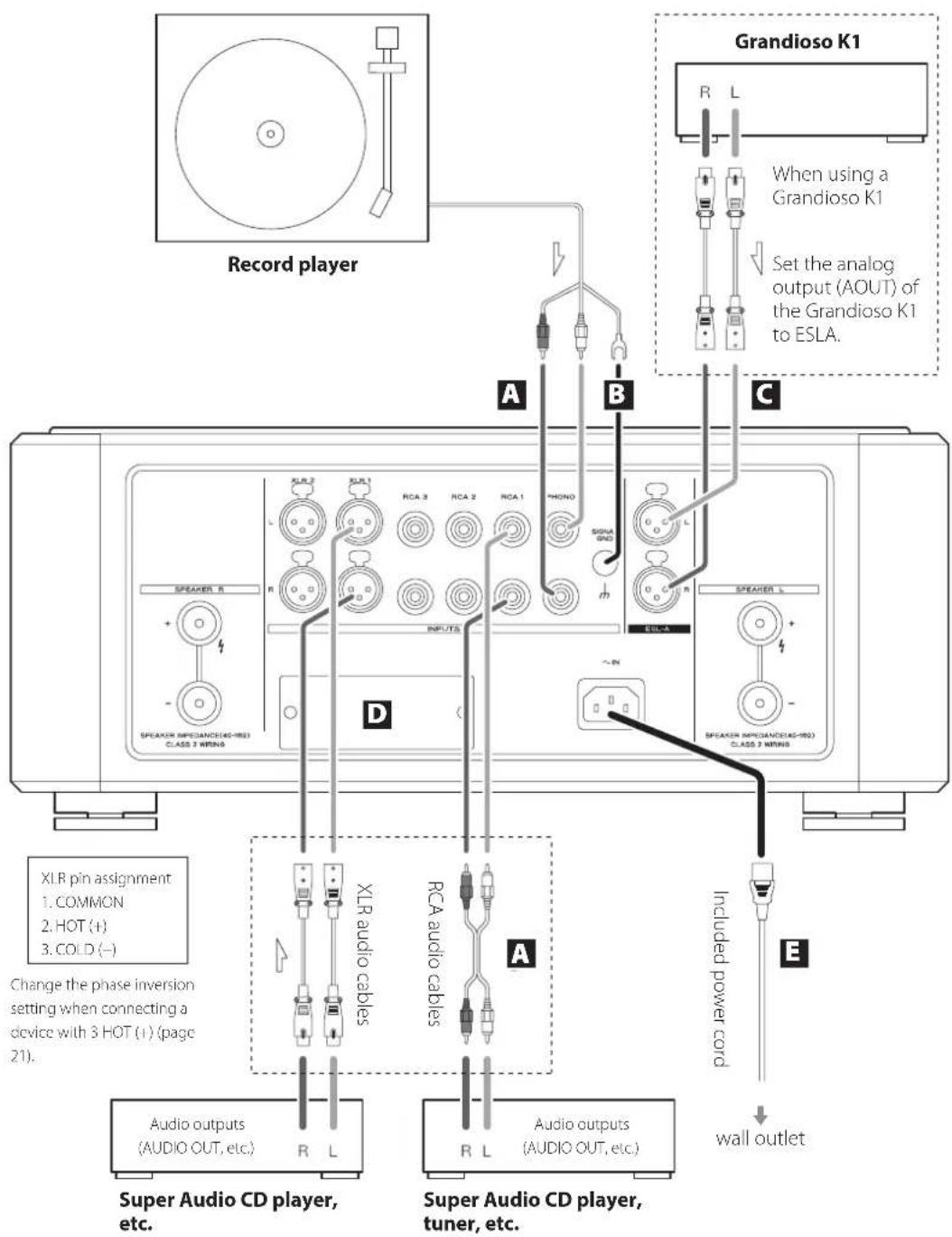
A Analog input (INPUTS) connectors
Connect the analog output connectors of Super Audio CD players, DVD players, cassette decks, tuners and other equipment to these connectors.
Connect the R connector of a pair on this unit to the right (R) connector of an output device and the L connector of the same pair on this unit to the left (L) connector of the output device.
Use commercially-available cables for connections.
For XLR connectors: Use a balanced XLR audio cable.
Insert a balanced XLR plug until the connector lever locks. Press this lever when disconnecting.
For RCA and PHONO connectors: Use an RCA audio cable.
Connect the white pin plugs to the white (L) connectors and connect the red pin plugs to the red (R) connectors.
- The XLR input connectors can be switched to 3 HOT (+) (page 21).
Connecting record players
This unit has a built-in phono equalizer. When connecting a record player, use the PHONO connectors.
- Always connect the record player's ground to the SIGNAL GND grounding terminal on this unit.
- Use the MM/MC (phono selection) button to set the cartridge type being used (page 19).
B SIGNAL GND grounding thermal
Using a commercially-available sheathed wire to connect this to the grounding terminal of a Super Audio CD player, power amplifier or other device might improve the audio quality.
- This is not an electrical safety ground.
C ES-LINK Analog (ESL-A) connectors
Use these to connect to a Grandioso K1 (page 12).
- Ordinary balanced cables (with XLR connectors) are used for connection. These connectors can only be used with compatible devices, however, because the transmission format is unique.
- Set the analog output (AOUT) of the Grandioso K1 to ESLA.
D Optional board slot
This slot is for installing an optional board that is sold separately.
E AC power inlet (\~IN)
Connect the included power cord to this socket. After completing all other connections, plug the power plug into a power outlet.
Use only a genuine Esoteric power cord. Use of other power cords could result in fire or electric shock.
At Esoteric, we use Esoteric MEXCEL stressfree cables for reference.
For detailed information, access the following website.
http://www.esoteric.jp/products/esoteric/accessory/indexe.html
text_image
R Right speaker Left speaker L S INPUTS SPEAKER IMPDANCE(40-183) CLASS 2 MIRING SPEAKER IMPDANCE(40-183) CLASS 2 MIRING SUEA 2 SUEA 1 RCA 3 RCA 2 RCA 1 PHONO SIGNAL GND ECLN R R S ASKER L SPEAKER IMPDANCE(40-183) CLASS 2 MIRINGNotes about speaker cables
- Use commercially-available speaker cables to connect the speakers.
- Use the shortest speaker cables possible. The longer the cable, the greater the resistance value and the more that damping performance is reduced. Moreover, length also increases impedance and capacitance, degrading the sound quality of high frequencies.
- Use left and right speaker cables that have the same length.
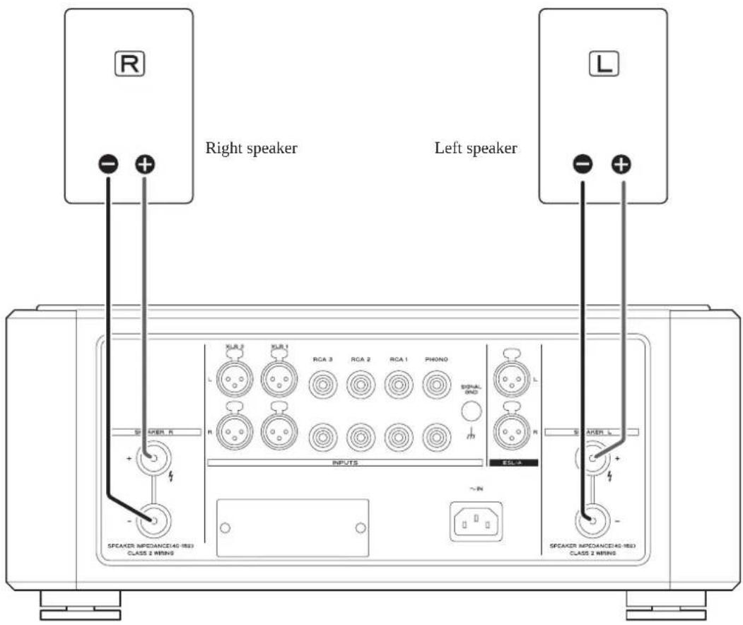
How to connect speaker cables
Use commercially-available speaker cables to connect the + terminal of the unit to the + terminal of the speaker and the - terminal of the unit to the - terminal of the speaker.
- Use speakers with at least 4 impedance.
- If the exposed tip of the core wire of a speaker cable contacts another cord or terminal, a short could occur.
Never allow a speaker cable to short. - Do not connect more than one amplifier to a speaker.
- Do not bundle speaker cables with power cords. Doing so could cause noise.
The power plug should always be disconnected when connecting speaker cables.
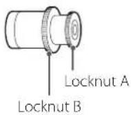
When using banana plugs
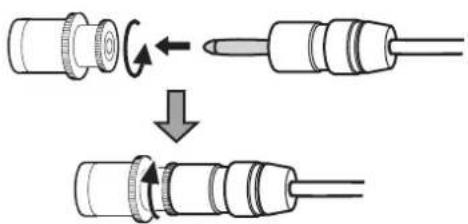
Loosen locknut A and insert the plug into the opening in the end of the terminal. Then, tighten locknut A.
text_image
Diagram illustrating the process of a mechanical component being rotated or flipped, with arrows indicating rotation and change.- Keep locknut B tightened when using.
- Carefully read the instructions for the banana plugs that you are using.
Notice about the European model
In accordance with European safety regulations, connecting banana plugs to speaker terminals is not allowed on European models. The holes into which banana plugs could be inserted have been covered with black caps. Connect speakers using bare wires or spade lugs. If a black cap should become separated from its terminal, return it to its original position.
When using bare wires
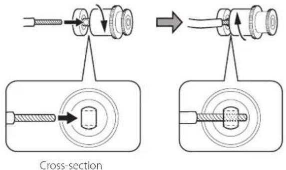
Loosen locknut B and insert the core wire from the side. Then, tighten locknut B.
- The hole for the insertion of the core wire is open on the left and right sides.
text_image
Cross-section- The maximum wire diameter that can be inserted is 4 mm (1/8").
When using spade lugs
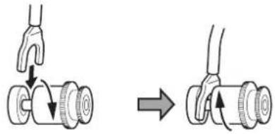
Loosen locknut B and place the terminal wire from the top or bottom. Then, tighten locknut B.
natural_image
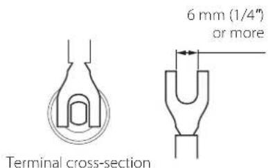
Diagram showing a hand gripping a cylindrical object with a curved handle, before and after a press or lifting operation (no text or symbols present)- When using a spade lug to connect, use one with an inside diameter of at least 6 mm (1/4").
text_image
6 mm (1/4") or more Terminal cross-sectionConnecting with a Grandioso K1
text_image
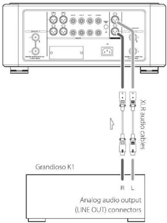
XL audio cables Grandioso K1 Analog audio output (LINE OUT) connectorsUse XLR audio cables to connect the ES-LINK Analog (ESL-A) connectors on this unit with the analog audio output (LINE OUT) connectors on the Grandioso K1.
- Set the analog output (AOUT) of the Grandioso K1 to ESLA.
Notes about the protection circuits
This unit has a DC protection circuit, an overcurrent protection circuit and an overheating protection circuit built-in.
When a protection circuit is operating, the power indicator blinks and one of the following error messages blinks on the display.
DCout ERR!
The DC protection circuit is active.
Turn the unit off once and wait several minutes before turning it on again.
OverCURNT!
The overcurrent protection circuit is active.
A short might have occurred with the +/- speaker cables. In this case, turn the unit off and check the speaker cable connections.
Over TEMP!
The overheating protection circuit is active.
The internal temperature has become high. Turn the unit off and wait a while for the temperature to decrease. You can also change the installation conditions to improve ventilation.
- If the overheating protection circuit continues to operate for 30 seconds, the unit will automatically turn itself off. After this, the POWER button will be disabled for as long as the internal temperature remains high.
If the indicator continues to blink even after likely causes have been eliminated, contact the store where you purchased the unit.
Precautions for use
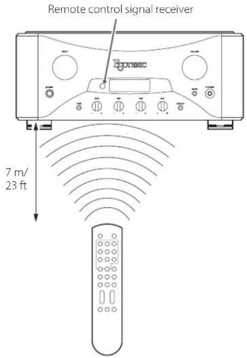
When using the remote control, point it toward the remote control signal receiver on the main unit from a distance of 7 m (23 ft) or less. Do not place obstructions between the main unit and the remote control.
Moreover, operation from an angle can make reception difficult, so use the remote facing the front of the main unit as much as possible.
text_image
Remote control signal receiver 7 m/ 23 ft- The remote control might not work if the remote control signal receiver is exposed to direct sunlight or bright light.
- Beware that use of this remote control could cause the unintentional operation of other devices that can be controlled by infrared rays.
Installing batteries
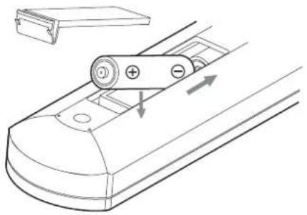
Remove the cover from the back of the remote control and insert two AAA batteries with their / oriented as shown in the case. Replace the cover.
natural_image
Technical line drawing of a mechanical device with labeled components and directional arrows (no text or symbols)When to replace batteries
If the distance required between the remote and the main unit decreases or if the unit stops responding to the remote buttons, replace both batteries with new ones.
Dispose of the used batteries according to the instructions on them or requirements set by your local municipality.
CAUTION

Misuse of batteries could cause them to rupture or leak, which might result in fire, injury or the staining of nearby materials.
Please read and observe the precautions on page 5 carefully.
text_image
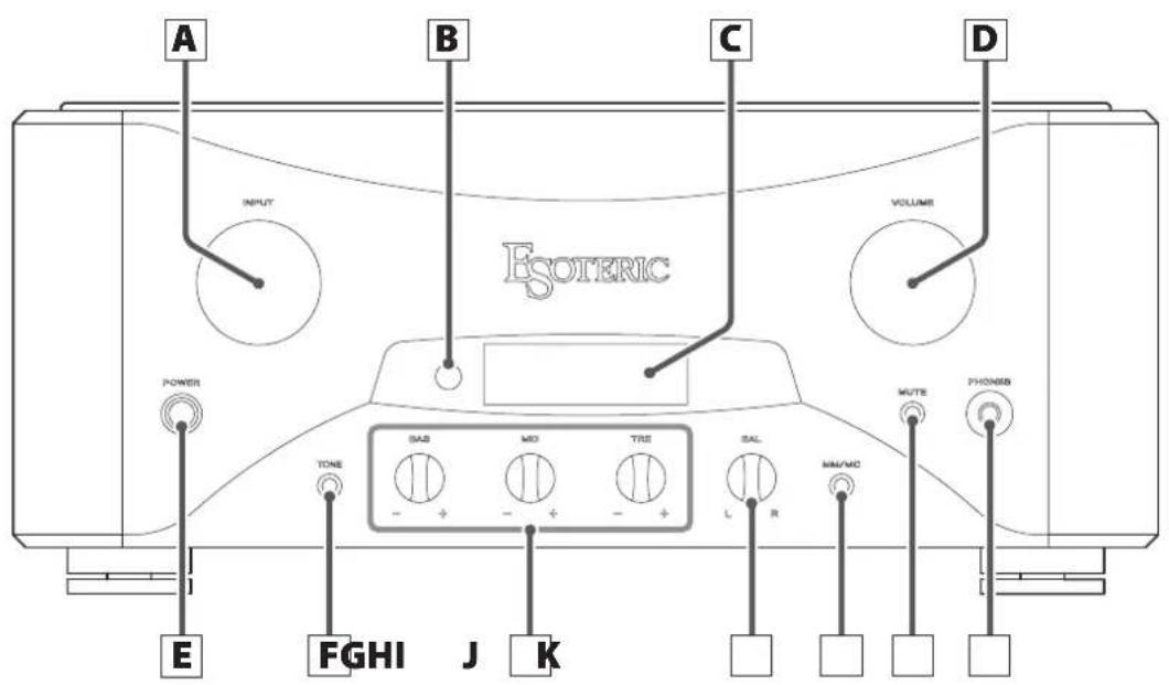
A B C D INPUT VOLUME ESOTERIC POWER TONE SAB MO TRS SAL MUTE PHONES E FGHI J K L RA INPUT knob
Turn this knob to select the active input. Select the connector that is connected to the device you want to play.
- You can change the names that are shown on the display for the connectors (page 21).
When the Settings Screen is open, use this to change setting values.
When inputting a source name, use this to move the cursor.
B Remote control signal receiver
This receives signals from the remote control. When using the remote control, point the end of it toward this receiver panel (page 13).
C Display
Shows the current input source name, volume, setting items, etc.
D VOLUME knob
Use to adjust the volume.
Turn this knob clockwise to increase the volume and counterclockwise to decrease it.

Sudden loud noises might cause hearing damage and other trouble. Always minimize the volume before starting playback, and adjust it to an appropriate level after playback begins.
Use to select characters when setting input source names.
E POWER button
Press to turn the unit on and off.
When the unit is on, the power indicator (ring around the button) lights blue.
- When not using the unit, turn it off.
- To protect your speakers, follow the proper procedures when you turn the unit on or off (pages 17 and 18).
Using headphones
F TONE bypass button
Use this to turn tone bypass on and off.
Press at least three seconds to open the Settings Screen.
G Tone controls
Use these to adjust the levels of different frequency ranges.
Turn toward + to increase the level, and turn toward - to decrease it.
Set these knobs to their center positions for a flat response (no adjustment).
BAS
Adjust the level of low frequencies.
MID
Adjust the level of medium frequencies.
TRE
Adjust the level of high frequencies.
- These adjustments only effect the output when tone bypass is off.
- When tone bypass is off, "TONE" appears at the top of the display.
H BAL (balance) knob
Adjust the left-right volume balance.
I MM/MC (phono selection) button
Set for the cartridge type (MM/MC) used by the player connected to the PHONO connectors (page 19).
Use to confirm characters when setting input source names.
J MUTE button
Press this button to temporarily mute the sound.
- When muted, "MUTE" blinks on the screen.
When the Settings Screen is open, press this to close it.
K PHONES jack
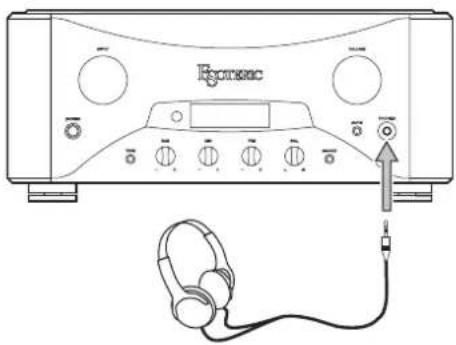
Connect headphones with a standard 6.3mm (1/4") stereo plug here.
- When a headphone plug is inserted, speaker sound output will stop.
text_image
EconacConnect a headphone plug (standard 6.3mm stereo) to the PHONES jack, and adjust the volume to a suitable level.
When using headphones, be careful not to turn the volume up too much.
text_image
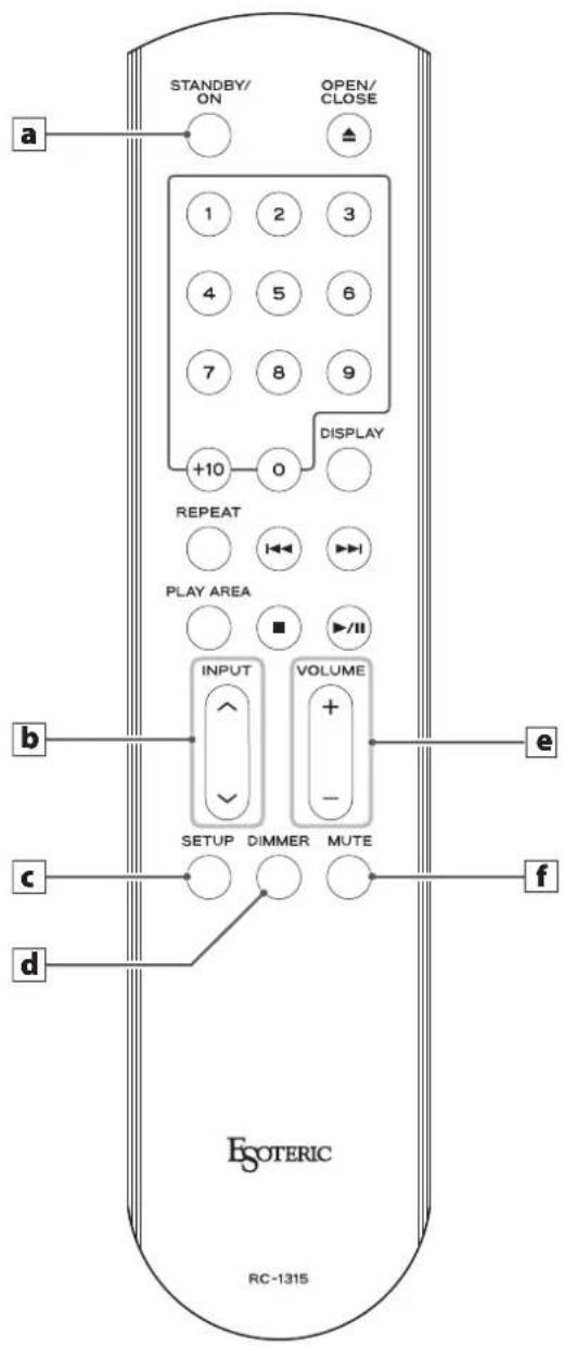
STANDBY/ ON OPEN/ CLOSE a 1 2 3 4 5 6 7 8 9 +10 0 DISPLAY REPEAT PLAY AREA INPUT VOLUME SETUP DIMMER MUTE e c f d ESOTERIC RC-1315If both the main unit and the remote control have buttons with the same function, we only explain procedures using one of them in this manual. However, the other can also be used in the same manner.
- The buttons not explained here do not function with this unit.
● This remote control can also be used for other Esoteric products.
a Setting (STANDBY/ON) button
On the Settings Screen, use to confirm selection of some settings and to input connector names.
- This button does not turn the unit on/off.
b INPUT (^^/∨) buttons
Press these buttons to switch between input sources. Select the connector that is connected to the device you want to play.
When the Settings Screen is open, use this to change setting values.
When inputting a source name, use this to move the cursor.
c SETUP button
Use with Settings Screen Menus 1, 2 and 3 (page 20).
d DIMMER button
Use to adjust the brightness of the display and indicator (page 19).
e VOLUME buttons (+/-)
Use to adjust the volume. Press the + button to increase the volume and the - button to decrease it.
Use to select characters when setting input source names.
f MUTE button
Press this button to temporarily mute the sound. Press again to restore the volume setting (page 18).
- When muted, "MUTE" blinks on the screen.
When the Settings Screen is open, press this to close it.
Turning the unit on
1 Turn on the connected input source devices.
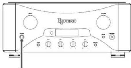
2 Press the POWER button to turn the unit on.
text_image
HcpomacPOWER
The power indicator lights blue.
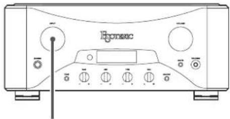
3 Turn the INPUT knob to select an input source.
text_image
EconsecINPUT
natural_image
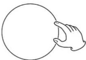
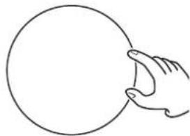
Simple line drawing of a hand holding a circle (no text or symbols)4 Play the source, and then adjust the volume by turning the VOLUME knob.
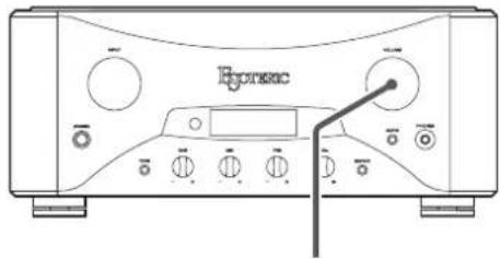
text_image
EpsonacVOLUME
natural_image
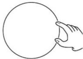
Simple line drawing of a hand holding a circle (no text or symbols)Sudden loud noises might cause hearing damage and other trouble. Always minimize the volume before starting playback, and adjust it to an appropriate level after playback begins.
Turning the unit off
There might be noise from the speakers if the unit is turned off suddenly. When you turn the unit off, follow the steps below.
1 If a connected device is playing back, stop playback.
2 Turn the unit's VOLUME knob counterclockwise to minimize the volume.
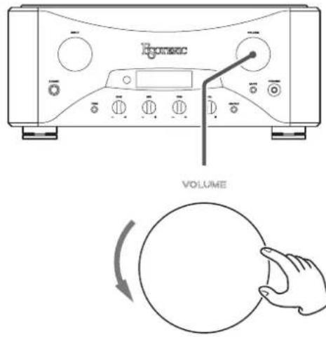
text_image
RONEC VOLUME● Always turn the volume to the minimum level before you turn the unit on or off. Failure to do so could cause sudden loud noises that might result in harm to your hearing or damage to the speakers when you turn the unit on.
3 Press the POWER button to turn the unit off.
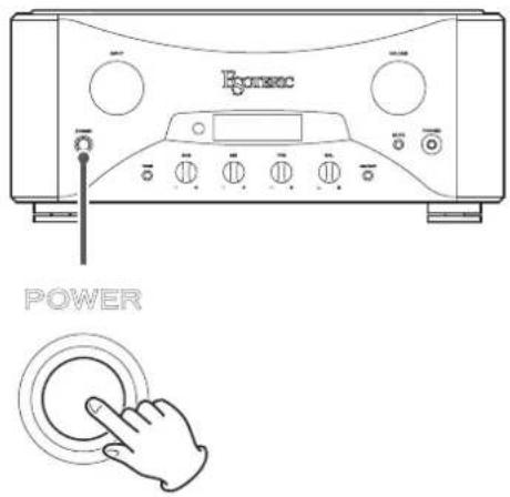
text_image
Ecorsec POWER4 Turn off the connected input source devices.
Muting the output
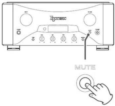
text_image
Ecopec MUTEPress the MUTE button to temporarily mute the sound. Press again to restore the volume setting.
- When muted, "MUTE" blinks on the screen.
- You can also restore the sound by turning the VOLUME knob or by pressing the VOLUME buttons (+/-).
Tone controls
You can separately adjust the levels of low (BAS), medium (MID) and high (TRE) frequencies.
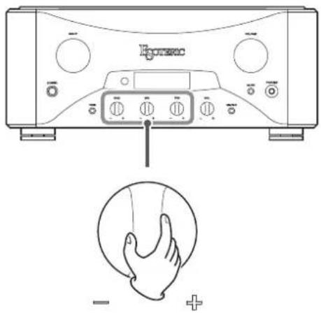
text_image
Epoere - +- These adjustments have no effect when tone bypass is on. Before adjusting them, press the TONE bypass button so that "TONE" appears at the top of the display.
Tone bypass
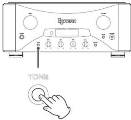
text_image
Котхас TONEWhen tone bypass is on, audio signals do not pass through the tone circuit before amplification.
When tone bypass is off, "TONE" appears at the top of the display.
Setting the cartridge type
Set the cartridge type being used by the record player connected to the PHONO connectors.
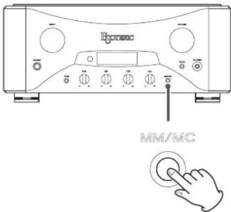
text_image
Hypersic MM/MCTurn the INPUT knob to set the input source to PHONO before pressing the MM/MC (phono selection) button to change the setting.
Adjusting the balance
Adjust the balance between the left and right output channels.
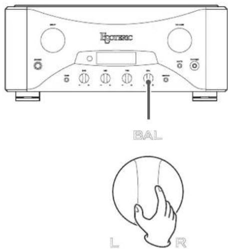
text_image
Ecopec BAL L RDimmer
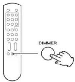
text_image
DIMMEREach time you press the DIMMER button, the brightness of the display and indicator change as follows.
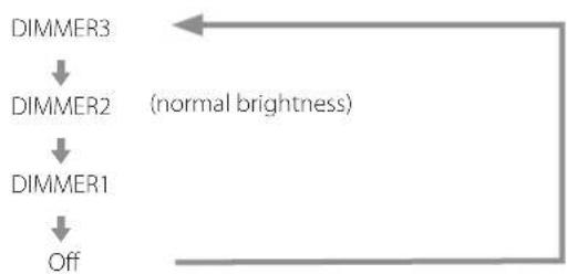
flowchart
graph TD
    A["DIMMER1"] --> B["DIMMER2"]
    B --> C["DIMMER3"]
    C --> D["Off"]
    style A fill:#f9f,stroke:#333
    style B fill:#f9f,stroke:#333
    style C fill:#f9f,stroke:#333
    style D fill:#f9f,stroke:#333
    note right of C (normal brightness)
- Even when set to off, the display will light at normal brightness for a few seconds when you press a button or turn a knob. If tone bypass is on, however, this will not light when the tone controls are turned.
- In setting mode, the display lights at normal brightness.
Basic operation
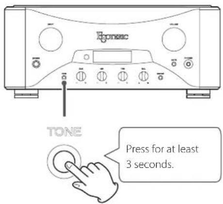
1 Press and hold the TONE bypass button for at least 3 seconds.
text_image
Epsonic TONE Press for at least 3 seconds.The MENU 1 icon appears on the display.
- You can also press the SETUP button on the remote control.
Opening Settings Menu 2
When Settings Menu 1 is open, press and hold the TONE bypass button for at least 3 seconds.
- You can also press and hold the SETUP button on the remote control for at least 3 seconds.
Opening Settings Menu 3
Show "goto MENU3" on Settings Menu 2, and press the MM/MC (phono selection) button.
- You can also press the Setting (STANDBY/ON) button on the remote control.
2 Press the TONE bypass button repeatedly to select the item to change.
- You can also repeatedly press the SETUP button on the remote control.
- When making settings, the MENU icon appears on the display.
- If you do nothing for 10 or more seconds, setting mode will end and ordinary display will resume.
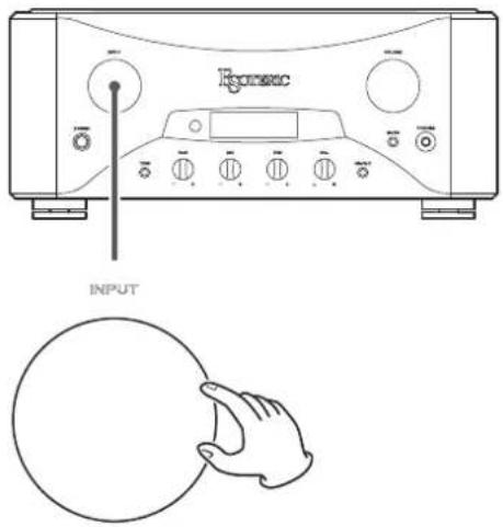
3 Turn the INPUT knob to change the setting.
text_image
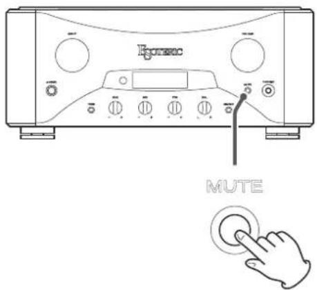
Roverac INPUT4 Press the MUTE button to complete making settings.
text_image
Ecopec MUTEIf you do nothing for 10 or more seconds, setting mode will end and ordinary display will resume.
- Settings are retained even if the power plug is disconnected.
In Settings Menu 1, you can make settings for the selected input source.
You can set the output level adjustment, phase inversion and input source name. You can set these independently for each of the inputs.
Adjusting the output level
LEVEL>\*\*\*
You can adjust the output level for the selected input.
You can set this to values between -18.0 dB and +18.0 dB in 0.5dB increments.
The default value is 0.0 dB.
Note about settings and sound quality
The Level (output level adjustment) setting items affect the volume. This unit's microcomputer analyzes these settings and the volume level value comprehensively to conduct unified control of volume amplification.
For this reason, unlike ordinary amplifiers that pass audio signals through multiple circuits, these settings will not degrade the audio quality.
Phase inversion
PHASE>\*\*\*
This switches the phase of the selected input connector.
If the XLR connector of the audio output device is pin 3 HOT, select INV.
By default, this is set to NOR.
NOR
No phase inversion
When using XLR input connectors, pin 2 is HOT.
INV
Phase inversion enabled
When using XLR input connectors, pin 3 is HOT.
Input source name
XLR1>\*\*\*
(This appears when the input source is XLR 1.)
You can change the names shown on the display for the unit's connectors when you turn the INPUT knob. You can set the names as you like (up to five characters).
EDIT
Use to change input source names.
Changing input source names
1 Show "EDIT", and press the MM/MC (phono selection) button.
You can also press the setting (STANDBY/ON) button on the remote control.
2 Enter the characters.
The cursor blinks beneath the character being input.
Use the INPUT knob to move the cursor, and use the VOLUME knob to select characters.
You can also use the remote control INPUT (∧/∨) buttons to move the cursor and its VOLUME (+/-) buttons to change the character.
3 When you have finished input, press the MM/MC (phono selection) button to confirm the change.
You can also confirm by pressing the setting (STANDBY/ON) button on the remote control.
- While entering the name, the volume and input connector cannot be changed.
• Available characters
English letters: A-Z, a-z
Numbers: 0–9
Symbols:!" # \$ % & ' () * + , - . / \ : ; <= > ? @ (blank)
In Settings Menu 2, you can make the following settings.
Illumination
Automatic display backlight off
Automatic power saving function
Volume display
You can also open Settings Menu 3 from this menu.
Illumination
LIGHT>\*\*\*
You can set whether or not the rings around the INPUT and VOLUME knobs light.
The default setting is "AUTO".
AUTO
When the knobs are operated, their rings light.
ON
The rings around the knobs will stay lit.
OFF
The rings around the knobs do not light.
Automatic display backlight off
DPaOFF>\*\*\*
You can set the display backlight to automatically turn off if no operation is conducted for a certain amount of time. By default, the setting is ON.
ON
If no operation is conducted for 10 minutes, the display automatically turns off.
OFF
The display will not turn off, but it will dim to the same brightness as DIMMER1 to protect the display from wear.
- We recommend setting this to "ON" because brightness irregularities might occur if the same information is shown without change on the display for a long time.
Automatic power saving function
APS>\*\*\*
- By default, the setting is 30m.
If there is no audio input (continuous silence) from the selected input source for the set amount of time, the unit will turn off automatically.
- Audio input from input sources other than the one selected has no effect on the operation of the automatic power saving function.
30m
30 minutes
60m
60 minutes
90m
90 minutes
120m
120 minutes
OFF
The automatic power saving function is disabled.
Settings Menu 3
Volume display
Vdp>***
This sets the size of the characters and the units used to show the volume on the display.
L dB
Large characters show dB units.
The volume can be adjusted from -95.0 to +24.5 dB in 0.5dB steps.
N\_dB
Normal-sized characters show dB units.
The volume can be adjusted from -95.0 to +24.5 dB in 0.5dB steps.
L\_STEP
Large characters show steps.
The volume can be adjusted from 0.5 to 120.0 in 0.5 steps.
N\_STEP
Normal-sized characters show steps.
The volume can be adjusted from 0.5 to 120.0 in 0.5 steps.
Open Settings Menu 3
goto MENU3
Press the MM/MC (phono selection) button to open Settings Menu 3. You can also press the setting (STANDBY/ON) button on the remote control.

Settings Menu 3 includes a setting item related to amplification. This setting could result in damage to speakers if set incorrectly.
In Settings Menu 3, you can make the following setting.
Through output
Through output
THRU>***
Set whether to use the input connectors as signal through connectors. By default, the setting is OFF.
OFF
No through inputs are set.
XLR1
XLR2
RCA1
RCA2
RCA3
Only the signals from the selected input connectors bypass the preamp and are input directly to the power amplifier.

If you select inputs connected to an ordinary line-level device, signals that are too strong could be output to the speakers, resulting in damage to them.
"THRU" appears on the display instead of the volume level set by using the VOLUME knob.
For example, if you connect the pre-out connectors (for example, FRONT L/R) of an AV amplifier to this unit's RCA 2 connectors, and set RCA2 to THRU, you can use the speakers connected to this unit as the front speakers of the AV amplifier. (The AV amplifier controls volume adjustment when the input source is set to "RCA2".)
- The VOLUME knob will not affect the volume of the input connectors set to THRU.

Always connect a device that has a volume control to the input connectors set to THRU. Use that device to minimize the volume before switching the input source, and then gradually raise the volume level.
Restoring factory settings
You can restore the factory default settings, erasing all changes in memory.
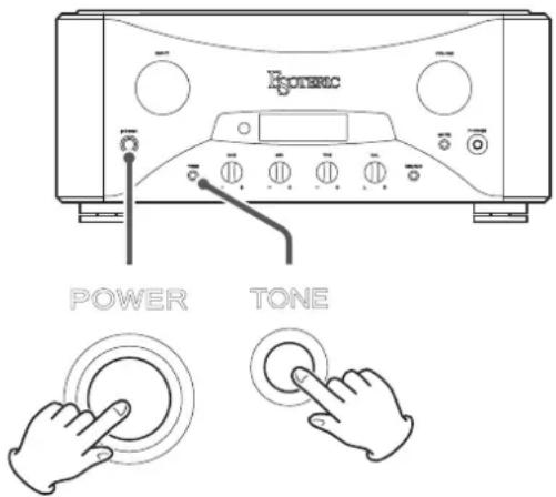
Turn the unit on while pressing and holding the TONE bypass button.
text_image
HOTRAC POWER TONETroubleshooting
If you experience a problem with this unit, please take a moment to review the following information before requesting service. Moreover, the problem might be caused by something other than this unit. Please also check the operation of the connected units.
If this product still does not operate correctly, contact the retailer where you purchased it.
The unit does not turn on.
→ Check that the power cord is plugged into a working power outlet.
→ Check that the power cord is properly connected to this unit.
The unit automatically turns off.
→ This is because the automatic power saving function turned it off.
Press the POWER button on the main unit to turn it on.
Change the automatic power saving setting if necessary (page 22).
Remote control does not work.
→ Turn the main unit on (page 17).
If the batteries are exhausted, replace both of them with new ones (page 13).
The remote control will not work if there is an obstruction between it and the main unit. Point the remote control toward the main unit and use it within 7 m (23 ft) of the front panel (page 13).
A television or other device is operating improperly.
The use of this unit's remote control might cause some televisions with wireless remote control functions to operate incorrectly.
Volume display blinks.
The volume value exceeds the maximum total gain of this unit. Lower the volume until the display stops blinking.
An error message appears.
→ A protection circuit is active. Turn the unit off and eliminate the cause (page 12).
A short might have occurred with the +/- speaker cables. Check the speaker cable connections (page 12).
The stereo sound position is irregular.
→ Check that neither of the speakers has a connection cable with +/- reversed.
This unit uses a microprocessor, so noise and other external interference could cause it to stop functioning properly. If this occurs, turn the unit off once, and then restart it after waiting for about one minute.
Speaker output
| Output | 30 W + 30 W (8 Ω) |
| 60 W + 60 W (4 Ω) | |
| Total harmonic distortion | 0.009% |
| (1 kHz, 8 Ω, 30 W) | |
| Frequency response | 10 Hz - 150 kHz |
| (+0/-3.0 dB at 1W output) | |
| S/N ratio (when 30W/8Ω output, JEITA) | |
| ES-LINK Analog, XLR, RCA input | 103 dB |
| PHONO (MM) input | 101 dB |
| PHONO (MC) input | 82 dB |
| Damping factor | 100 |
| Minimum compatible impedance | 4 Ω |
| Speaker output connectors | 1 pair (L/R) |
| (screw type) | |
Headphone output
| Output | 1000 mW(32 Ω, 10% distortion) |
| Headphone output jack | 1(Standard 6.3mm (1/4") stereo jack) |
Inputs
| ES-LINK Analog connectors | 1 pair (L/R) |
| XLR connectors | 2 pairs (L/R) |
| RCA connectors | 3 pairs (L/R) |
| PHONO connectors | 1 pair (L/R) |
| (MM/MC switchable) |
Input impedance
| ES-LINK Analog | - (current input) |
| XLR, RCA | 10 kΩ |
| PHONO (MM) | 47 kΩ |
| PHONO (MC) | 100 Ω |
Gain
| Preamplifier | 24.5 dB |
| (when VOLUME at maximum) | |
| Power amplifier | 35 dB |
Tone controls
| BAS | ±12 dB (63 Hz) |
| MID | ±12 dB (630 Hz) |
| TRE | ±12 dB (14 kHz) |
General
| Power supply | |
| Model for Europe/Hong Kong | AC 230 V, 50 Hz |
| Model for USA/Canada | AC 120 V, 60 Hz |
| Power consumption | |
| Model for Europe/Hong Kong | 250 W |
| 175 W (when no signal) | |
| Model for USA/Canada | 205 W |
| 175 W (when no signal) | |
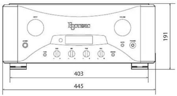
| External dimensions .445 × 191 × 470 mm (17 5/8" × 7 5/8" × 18 5/8") | |
| (W × H × D) (including protrusions) | |
| Weight | 30.0 kg (66 1/4 lb) |
| Operating temperature | +5°C to +35°C |
Included accessories
| Power cord × 1 |
| Remote control (RC-1315) × 1 |
| Batteries for remote control (AAA) × 2 |
| Felt pads × 4 |
| Owner's manual (this document) × 1 |
| Warranty card × 1 |
- Specifications and appearance are subject to change without notice.
● Weight and dimensions are approximate. - Illustrations in this Owner's Manual might differ slightly from production models.
text_image
Egoerix 191 403 445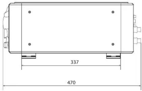
text_image
337 470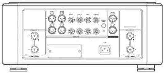
text_image
Technical diagram of a device control panel with labeled ports and buttonsDimensions in millimeters (mm)
CAUTION
RISK OF ELECTRIC SHOCK DO NOT OPEN

ATTENTION : POUR RÉDUIRE LE RISQUE D'ÉLECTROCUTION, NE RETIREZ PAS LE CAPOT (OU L'ARRIÈRE). AUCUNE PIÈCE INTERNE N'EST RÉPARABLE PAR L'UTILISATEUR. CONFIEZ TOUTE RÉPARATION À UN SERVICE APRÈS-VENTE QUALIFIÉ.

natural_image
Symbolic icon of a person pushing a large stack of books, enclosed in a circle with a diagonal line (no text or symbols)natural_image
Pure mechanical cross-section diagram without any text, numbers, or symbolstext_image
Diagram illustrating the process of a mechanical component being rotated or flipped, with arrows indicating rotation and change.natural_image
Diagram showing a hand gripping a cylindrical object with a curved arrow indicating rotation (no text or symbols present)natural_image
Technical line drawing of a mechanical device with labeled components and directional arrows (no text or symbols)H Commande BAL (balance)
natural_image
Simple line drawing of a hand holding a circle (no text or symbols)natural_image
Front view of a portable electronic device with buttons and a central display (no visible text or symbols)VOLUME
natural_image
Simple line drawing of a hand holding a circle (no text or symbols)
natural_image
Front view of a portable electronic device with control knobs and buttons (no visible text or labels)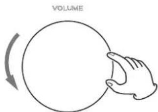
text_image
VOLUMEnatural_image
Front view line drawing of a portable electronic device with control knobs and buttons (no readable text or symbols)
natural_image
Front view of a portable electronic device with control knobs and buttons (no visible text or symbols)
natural_image
Front view of a portable electronic device with control knobs and buttons (no visible text or labels)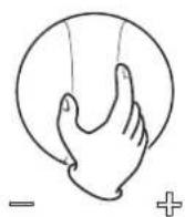
text_image
Ecopec INPUTtext_image
Ecorsec MUTEtext_image
Technical diagram of a device control panel with labeled ports and buttonsnatural_image
Silhouette of a person climbing a ladder inside a circular frame (no text or symbols)natural_image
Pure mechanical cross-section diagram without any text, numbers, or symbolstext_image
Diagram illustrating the process of a mechanical component being shifted, showing step-by-step assembly with rotation and end states.natural_image
Diagram showing a hand gripping a cylindrical object with directional arrows indicating motion (no text or symbols)natural_image
Technical line drawing of a remote control device with battery and directional arrows indicating motion (no text or symbols)H Mando BAL (balance)
natural_image
Simple line drawing of a hand holding a circle (no text or symbols)natural_image
Simple line drawing of a hand holding a circle (no text or symbols)
text_image
Ransec VOLUMEtext_image
Enersec POWERtext_image
Ecopec MUTEtext_image
Power - +text_image
PORATE INPUTtext_image
Ecopec MUTEtext_image
Technical diagram of a device control panel with labeled ports and buttonsThis appliance has a serial number located on the rear panel. Please record the serial number and retain it for your records.
Model name: Grandioso F1 Serial number