S500 - Effect machine Antari - Free user manual and instructions
Find the device manual for free S500 Antari in PDF.

| Product Type | Snow Machine |
| Brand | Antari |
| Model | S-500 |
| Dimensions (L x W x H) | 592 x 551 x 651 mm |
| Weight | 37.2 kg |
| Power Supply (US model) | AC 100-120V, 50/60 Hz, 7.5 A |
| Power Supply (EU model) | AC 220-240V, 50/60 Hz, 3.8 A |
| Output Power | 9000 W |
| Tank Capacity | 20 liters |
| Fluid Consumption | 400 ml/min |
| Compatible Fluids | Antari SLN, SLAN, SLH, SLC Snow Foam Fluid |
| Ambient Temperature | 5 °C to 40 °C |
| Control | DMX, timer, manual, wireless (WTR-20), W-DMX |
| DMX Channels | 2 channels |
| Connectors | Neutrik PowerCon (power), XLR 3 and 5-pin (DMX) |
| Included Accessories | Power cable, filling hose, 20L tank, 10 m hose, nozzle |
| Maintenance | Clean with a dry cloth, rinse with distilled water before storage |
| Safety | 5A circuit breaker, moisture protection, min. distance 50 cm around |
| Main Functions | Continuous mode, timer, adjustable volume (1-100%), fan speed (20-100%) |
| Remote Control | SC-3 wired (optional), W-2 wireless (optional) |
| Repairability | No user-serviceable parts, contact Antari dealer |
Frequently Asked Questions - S500 Antari
User questions about S500 Antari
0 question about this device. Answer the ones you know or ask your own.
Ask a new question about this device
Download the instructions for your Effect machine in PDF format for free! Find your manual S500 - Antari and take your electronic device back in hand. On this page are published all the documents necessary for the use of your device. S500 by Antari.
USER MANUAL S500 Antari
natural_image
Exterior view of a black-and-white photo of an open industrial machine with a coiled hose and control panel (no visible text or symbols)
CONFORMS TO ANSI/UL STD.73 CERTIFIED TO CAN/CSA STD. C22.2 NO.68


English Français Deutsch
中文
Safety Information

Please read the following safety information carefully before operating the machine. This information includes important safeguards about installation, usage, and maintenance. Pay attention to all warning labels and instructions in this manual and printed on the machine.
If you have questions about how to operate the machine safely, please contact your local Antari dealer for help.
Keep this device dry.
Always connect to a grounded circuit to avoid risk of electrocution.
Before connecting the machine to power, always check the voltage indicated on the machine matches to your local AC voltage. Do not use the machine if the AC power voltage does not match.
Disconnect the machine from AC power before servicing and when not in use.
This product is for indoor use only! Do not expose to rain or moisture. If fluid is spilled, disconnect AC power and clean with a damp cloth. If fluid is spilled onto electronic parts, immediately unplug the machine and contact your local Antari dealer for advice.
No user serviceable and modifiable parts inside. Never try to repair this product, an unauthorized technician may cause damage or malfunction to the machine.
For adult use only. Never leave the machine running unattended.
Install the machine in a well-ventilated area. Provide at least 50 cm of space around the machine.
Never add flammable liquid of any kind to the machine.
Make sure there are no flammable materials close to the machine while operating.
Only use Antari fluid. Other fluid may lead to a heater clog and malfunction.
If the machine fails to work, unplug the machine and stop operation immediately.
Contact your local Antari dealer for advice.
Before transporting the machine, make sure the fluid tank is completely drained.
. Snow fluid may present health risks if swallowed. Do not drink snow fluid. Store it securely. In case of eye contact or if fluid is swallowed, immediately look for medical advice.
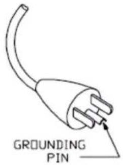
This appliance must be grounded. In the event of malfunction or breakdown, grounding provides a path of least resistance for electric current to reduce the risk of electric shock. This appliance is equipped with a cord having an equipment-grounding conductor and a grounding plug. The plug must be plugged into an appropriate outlet that is properly installed and grounded in accordance with all local codes and ordinances.
DANGER – Improper connection of the equipment-grounding conductor can result in a risk of electric shock. Check with a qualified electrician or serviceman if the grounding instructions are not completely understood, or if in doubt as to whether the appliance is properly grounded. Do not modify the plug provided with the appliance – if it will not fit the outlet, have a proper outlet installed by a qualified electrician
IMPORTANT SAFETY INSTRUCTIONS
WARNING – When using electric appliances, basic precautions should always be followed, including the following
a) Read all the instructions before using the appliance
b) To reduce the risk of injury, close supervision is necessary when an appliance is used near children.
c) Do not contact moving parts.
d) Only use attachments recommended or sold by the manufacturer.
e) Do not use outdoors.
f) For a cord-connected appliance, the following shall be included:
- To disconnect, turn all controls to the off ("O") position, then remove plug from outlet.
- Do not unplug by pulling on cord. To unplug, grasp the plug, not the cord.
- Unplug from outlet when not in use and before servicing or cleaning.
- Do not operate any appliance with a damaged cord or plug, or after the appliance malfunctions or is dropped or damaged in any manner. Return appliance to the
nearest authorized service facility for examination, repair, or electrical or mechanical adjustment.
g) For a portable appliance – To reduce the risk of electrical shock, do not put in water or other liquid. Do not place or store appliance where it can fall or be pulled into a tub or sink.
h) For a grounded appliance – Connect to a properly grounded outlet only. See Grounding Instructions.
GROUNDING INSTRUCTIONS
This appliance must be grounded in the event of malfunction or breakdown, grounding provides a path of least resistance for electric current to reduce the risk of electric shock. This appliance is equipped with a cord having an equipment-grounding conductor and a grounding plug. The plug must be plugged into an appropriate outlet that is properly installed and grounded in accordance with all local codes and ordinances.
DANGER – Improper connection of the equipment-grounding conductor can result in a risk of electric shock. The conductor with insulation having an outer surface that is green with or without yellow stripes is the equipment-grounding conductor. If repair or replacement of the cord or plug is necessary, do not connect the equipment-grounding conductor to a live terminal. Check with a qualified electrician or servicemen if the grounding instructions are not completely understood, or if in doubt as to whether the appliance is properly grounded. Do not modify the plug provided with the appliance. If it will not fit the outlet, have a proper outlet installed by a qualified electrician.
DANGER – improper connection of the equipment-grounding conductor can result in a risk of electric shock. Check with a qualified electrician or serviceman if the grounding instructions are not completely understood, or if in doubt as to whether the appliance is properly grounded. Do not modify the plug provided with the appliance – if it will not fit the outlet, have a proper outlet installed by a qualified electrician.
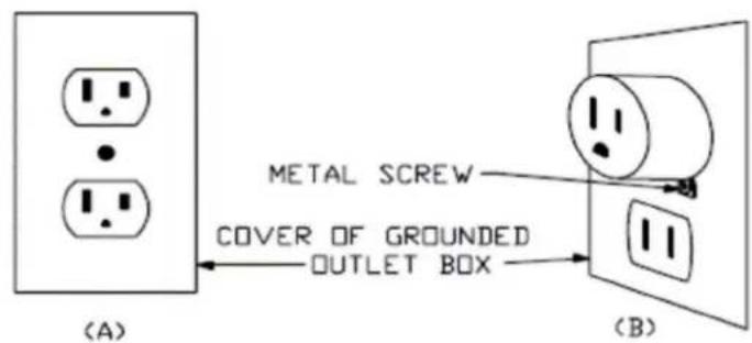
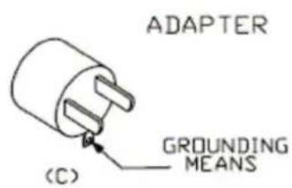
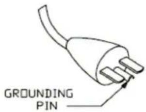
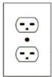
This appliance is for use on a nominal 120V circuit and has a grounding plug that looks like the plug illustrated in sketch A in Figure 73.1. A temporary adaptor, which looks like the adaptor illustrated in sketches B and C, may be used to connect this plug to a 2 pole receptacle as shown in sketch B if a properly grounded outlet is not available. The temporary adaptor should be used only until a properly grounded outlet can be installed by
a qualified electrician. The green colored rigid ear, lug, and the like, extending from the adaptor must be connected to a permanent ground such as a properly grounded outlet box cover. Whenever the adaptor is used, it must be held in place by the metal screw.
natural_image
Simple diagram of two identical electrical socket symbols with dots, no text or labels present(D)
Unpacking and Inspection
Immediately upon receiving the machine, carefully unpack the carton, check the content to ensure that all parts are present and have been received in good condition. If any parts appear damaged or mishandled from shipping, notify the shipper immediately and retain the packing material for inspection.
What is included: 1 x S-500 Snow Machine
1 x Power Cord
1 x User Manual
1 x Fluid Tank Feed Tube
1 x 20 Liter Fluid Tank
1 x Air Hose 10 Meters for S-500 / 20 Meters for S-500L
1 x Nozzle
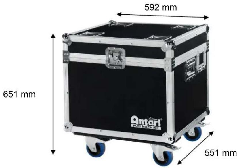
Product Dimensions
S-500 Model
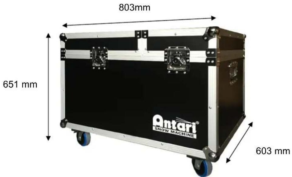
S-500L Model
Product Overview
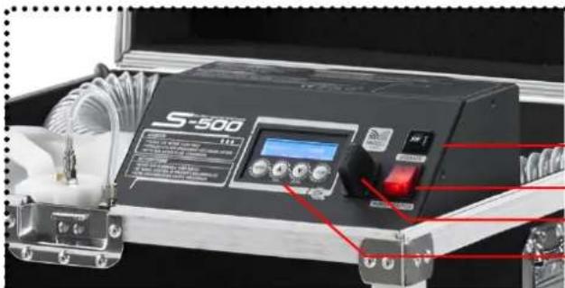
natural_image
Close-up of a S-500 industrial control device with visible buttons and wiring (no readable text or symbols)S-500 Control Panel
Breaker
Main Power Switch
Wireless Antenna
Control Panel
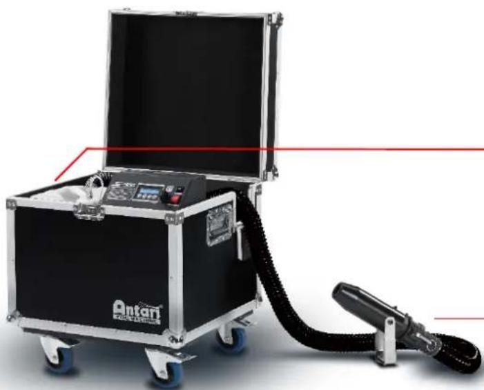
natural_image
Exterior view of an open black and silver testing machine with a connected hose and control panel (no visible text or symbols)Tank Capacity: 20 liters
Nozzle
XLR 3-Pin DMX Connector
XLR 5-Pin DMX Connector
Neutrik PowerCon
SC-3 Remote Control (Optional)
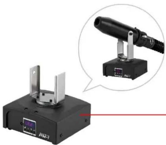
natural_image
Exterior view of a black-and-white optical instrument with a magnified inset showing its internal components (no text or symbols visible)PM-1 Pan Motor (Optional)
Setting Up
Step 1: Place the machine on a flat surface and in a suitably large area with at least 50 cm open space around the machine.
Step 2: Fill the fluid tank with Antari approved fluid.
Step 3: Connect the machine to a suitably rated power supply. To determine the power requirement for the machine refer to the label on the back of the machine.

Always connect the machine to a protected circuit and ensure it is properly grounded to avoid risk of electrocution.
Step 4: Turn on the machine, press the [VOLUME]/[DOWN] button on the control panel to start making snow.
Step 5: To turn off the machine, press the [STOP] button and put the power switch to the OFF position.
Operation
Control Panel Operation
The machine can be operated with onboard digital control interface

| Button Function | |
| [MENU] Scroll through setting menu | |
| [UP]/[TIMER] | Up/Activate Timer function |
| [DOWN]/[VOLUME] | Down/Activate Volume function |
| [STOP] | Deactivate Timer/Volume function, Escape from menu |
Language Setting
To switch the language used for the control interface, press the [Menu] button BEFORE turning on the machine and HOLD it until the LCD screen flashes twice. After the two flashes, press [Menu] to choose the language: English and 中文 (Chinese). After choosing the desired language, press [STOP] to memorize the setting.
Control Menu
| Timer IntervalXXX Sec | Set interval time at timer mode from 15 to 360 sec |
| Timer DurationXXX Sec | Set duration time at timer mode from 5 to 120 sec |
| Timer OutputXXX % | Set output volume in Timer mode between 1 and 100 % |
| Volume OutputXXX % | Set output volume in Volume mode between 1 and 100 % |
| Fan SpeedXXX % | Set fan speed from 20 to 100% |
| DMX-512Address: XXX | Set DMX/W-DMX address from 1 to 511 |
| W-DMXPowerXX | Turn On/Off W-DMX function |
| W-DMX ResetXX | Unlink from a W-DMX transmitter |
| WirelessXX | Turn On/Off wireless remote feature |
| Wireless RegisterUp:Pair Down:Del | Pair/unpair wireless remote.*This menu will not be shown when Wireless is turned off. |
| Run Last SettingXX | Turn On/Off run last setting function |
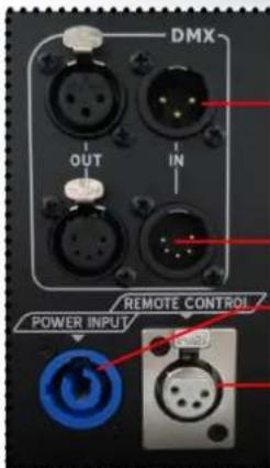
DMX Connector Pin Assignment
The machine provides a 3- or 5-pin XLR connector for DMX connection. The diagram below indicates pin assignment information.
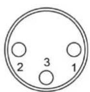
3 Pin XLR
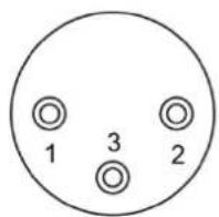

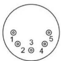
5 Pin XLR
| Pin Function | |
| 1 | Ground |
| 2 | Data- |
| 3 | Data+ |
DMX Operation
Making the DMX Connection – Connect the machine to a DMX controller or to one of the machines in the DMX chain. The machine uses a 3-pin XLR connector for DMX connection, the connector is located on the rear of the machine.

Address Setup – Use control menu to set DMX address. The machine occupies 2 control channels. The starting address is defined as the first channel from which the machine will respond to the controller. Always double check to make sure there are no overlapping channels in order to control the machine correctly.
DMX Channel Function
| Channel 1 DMX Value Range Function | ||
| Snow Output Level | 0 – 5 Snow off | |
| 6 – 255 Snow Output 1 – 100% | ||
| Channel 2 DMX Value Range Function | ||
| Fan Output Level | 0 – 5 Fan 20% | |
| 6 – 255 Fan 21 – 100% | ||
WTR-20 Wireless Remote Kit Operation
Wireless remote control system W-2 consists of a transmitter equipped with two buttons to activate, deactivate and adjust output level; with an onboard receiver attached to the front panel of S-500 snow machine.

natural_image
Close-up of a metallic remote control with four buttons (A, B, C, D) and a blue indicator light (no text or symbols visible)W-2 Wireless Transmitter

natural_image
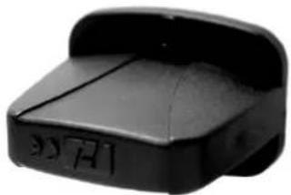
Black plastic object with engraved markings, no visible text or symbolsWireless Receiver
Button Function
| [A] | Activate | output |
| [B] | Deactivate | output |
| [C] Increase output level | ||
| [D] Decrease output level | ||
In a free open space the effective distance is 50 meters, actual usage depends on obstacle level; the effective distance is 10-25 meters.
Registering a transmitter
Transmitters can be paired or deleted from the receiver. Each receiver can pair up to 10 transmitters. Follow below diagram to pair or delete transmitter.

flowchart
graph TD
    A["Press and hold before power up"] --> B["Wireless Register Up:Pair Down:Del"]
    B --> C["Pair"]
    B --> D["Delete"]
    C --> E["Wireless Register Press button"]
    D --> F["Wireless Register Delete......"]
    E --> G["Wireless Register Pair Completed"]
    F --> H["Wireless Register Delete Completed"]
    I["STOP Press to finish and exit menu"] --> J["End"]
IMPORTANT NOTE: Wireless register menu will only be shown when Wireless is turn ON Transmitter battery replacement
If the effective distance seems to decrease, it is possible the battery level is low and requires replacement. In order to replace the battery, undo the three screws on the back of transmitter to release the cover. Replace with same type and specification of battery which is 27A 12V.
SC-3 Wire remote Operation (Optional)
Wired remote control module SC-3 enables to control the machine from a remote location. With three push buttons and two rotary knobs to activate/deactivate, priming and output level adjustment.
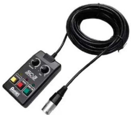
natural_image
Close-up of a black electronic device with a coiled cable and connector, no visible text or symbols.| Button/Knob Function | |
| [TOP LEFT KNOB] | Adjust pump output level |
| [TOP RIGHT KNOB] | Adjust blower output level |
| [LEFT BUTTON] | Max output on pump and blower |
| [CENTER BUTTON] | Turn On/Off SC-3 remote |
| [RIGHT BUTTON] | Max output on blower |
IMPORTANT NOTE:
[LEFT BUTTON] is meant for priming use, with a new tank of fluid or refill the fluid may not pump properly due to airlock in the pipeline, use this function to activate pump at maximum
output, the [RIGHT BUTTON] is used when needed to clean out residue at the tip of output nozzle. Both of these buttons will overtake output adjustment knobs.
Physical Installation
Important
- Use supplied mounting bracket or rigging clamp to install nozzle.
● Make sure installation location, fastening connecting, and rigging hardware can hold at least 10 times the weight of the nozzle.
● Make sure no combustible or flammable materials are nearby. - Secure nozzle with an approved safety cable that can hold at least 10 times the weight of nozzle.
● Make sure nozzle is installed in a well ventilated area. - Consider nozzle replacement and routine maintenance access when selecting installation location.
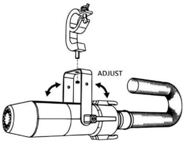
Adjustable Mouting Bracket
Adjust mounting bracket by loosening screws, set the nozzle to desired angle and tighten the screw to finish adjustment. Illustration below demonstrates how to adjust mounting bracket.
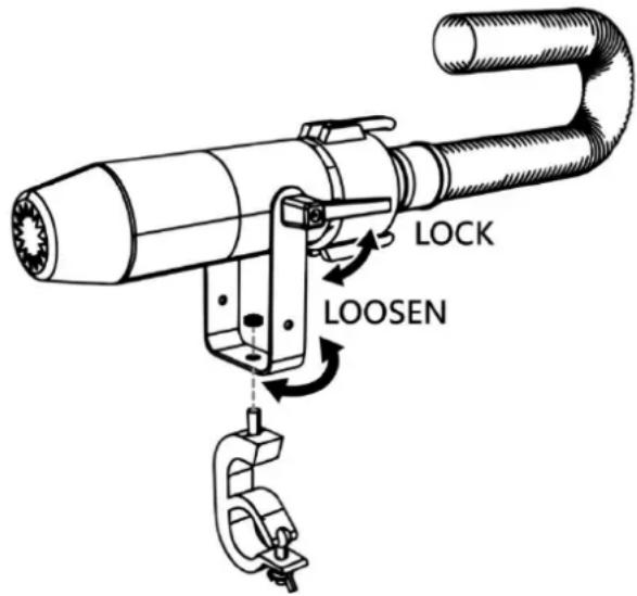
Mounting
Use screws for surface mounting or clamps for truss mounting.
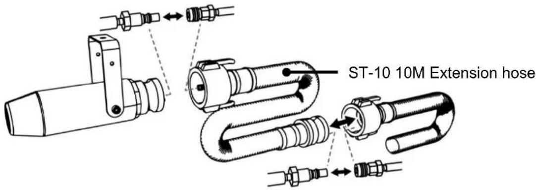
ST-10 Air Hose Extension (Optional)
The maximum air hose length is 20 meters. Illustration below demonstrates how to connect extension air hose.
Fluid
Only use Antari SL-5/SL-5A/SL-5N/SL-5AN liquid for the S-500 Snow Machine. The machine is tested and calibrated with this liquid to get the best output performance.
Warranty will be void if any other type of liquid is used, improper use of liquid may lead to machine failure and malfunction.
Service and Maintenance
Do not allow the machine to become contaminated.
Remove dust from air vents with air compressor, vacuum or a soft brush.
. Only use a damp cloth to clean the casing.
Before storing run distilled water through the system to help avoid condensing the
pump or heater.
It is recommended to run the machine on a monthly basis in order to achieve best performance and output condition.
Excessive dust, liquid and dirt built up will degrade performance and cause overheating.
Before storing away after operation, pump pure water through the system for at least 1 to 2 minutes. This will help clean out the remaining snow fluid and prevent pump from malfunction on next usage.
Breaker Reset

Disconnect AC power before resetting the breaker. Only replace fuse with same type and rating.
Step 1: Disconnect power cord from supply.
Step 2: Flip breaker to ON position.
Step 3: Turn on machine for testing.
Breaker
$$ 1 2 0 \mathrm{V} = 1 0 \mathrm{A} 2 5 0 \mathrm{V} $$
$$ 2 4 0 \mathrm{V} = 5 \mathrm{A} 2 5 0 \mathrm{V} $$

Technical Specifications
S-500
| - Input voltage | US model :AC 100-120V, 50 / 60HZ 7.5AEU model :AC 220-240V, 50 / 60Hz 3.8A |
| - Rated power | 900 W |
| - Fluid consumption | 400 ml/min |
| - Fluid tank capacity | 20 Liters (5.28gal) |
| - Compatible fluid | Antari SLN Snow Foam FluidAntari SLAN Snow Foam FluidAntari SLH Snow Foam FluidAntari SLC Snow Foam Fluid |
| - Ambient temp range | 5°C - 40°C (41°F - 104°F) |
| - Control | ManualTimerDMX 512Wireless (Optional)Wireless DMX (Optional) |
| - DMX channels | 2 channel |
| - Connection | Neutrik Powercon(Power)XLR 3-pin and 5-pin (DMX) |
| - Optional Accessories | W-DMX-PCBR Wireless DMX 512WTR-20 Wireless RemoteWTR-70 Wireless DMX 512 and RemoteWTR-80 Wireless RemoteWTR-90 Wireless DMXSC-3 Cable RemoteST-10 10 Meter Extension HosePM-1 Pan Motor |
| - Dimension | L592 W551 H651 mm(L23.31 W 21.69 H 25.63 inch)" |
| - Weight | 37.2 kg ( 82.01 lbs ) |
S-500L
- Dimension L803 W603 H651 mm
(L31.61 W23.74 H25.63 inch) - Weight 46.4 kg (102.29 lbs)
Notices de sécurité

natural_image
Exterior view of a black industrial testing machine with attached cable and control panel (no visible text or symbols)natural_image
Exterior view of a black-and-white photoelectric instrument with a magnified inset showing its internal components (no text or symbols visible)PM-1 Pan motor (facultatif)
Mise en service
natural_image
Close-up of a silver remote control with four buttons (A, B, C, D) and a blue indicator light on the left (no text or symbols beyond icons)natural_image
Black plastic object with engraved markings, no visible text or symbolsRécepteur sans fil
Bouton Fonction
flowchart
graph TD
    A["Press and hold before power up"] --> B["Wireless Register Up:Pair Down:Del"]
    B --> C["Pair"]
    B --> D["Delete"]
    C --> E["Wireless Register Press button"]
    D --> F["Wireless Register Delete......"]
    E --> G["Wireless Register Pair Completed"]
    F --> H["Wireless Register Delete Completed"]
    I["STOP Press to finish and exit menu"] --> J["End"]
natural_image
Black SC-B electrical testing device with attached black cable and connector (no visible text or symbols)Montage
natural_image
Exterior view of a black-and-white optical instrument with a magnified inset showing its internal structure (no text or symbols visible)natural_image
Close-up of a metallic remote control with four buttons (A, B, C) and a blue indicator light (no text or symbols beyond labels)W-2 Sendeeinheit
natural_image
Black plastic device with a curved top and side slots (no visible text or symbols)Funkempfänger
Taste Funktion
flowchart
graph TD
    A["Press and hold before power up"] --> B["Wireless Register Up:Pair Down:Del"]
    B --> C["Pair"]
    B --> D["Delete"]
    C --> E["Wireless Register Press button"]
    C --> F["Wireless Register Pair Completed"]
    D --> G["Wireless Register Delete......"]
    D --> H["Wireless Register Delete Completed"]
    I["STOP Press to finish and exit menu"] --> H