174T - Thermometer Testo - Free user manual and instructions
Find the device manual for free 174T Testo in PDF.
| Product type | Data logger thermometer |
| Brand | Testo |
| Model | 174T |
| Measuring range | -30 to +70 °C |
| Accuracy | ±0.5 °C (-30 to +70 °C) |
| Resolution | 0.1 °C |
| Sensor type | Internal NTC temperature sensor |
| Power supply | 2 CR2032 lithium button cells, 3 V |
| Battery life | 500 days (at 15 min intervals, +25 °C) |
| Memory | 16,000 measured values |
| Measurement interval | 1 min to 24 h (adjustable) |
| Protection rating | IP65 |
| Interface | USB (via dedicated interface and ComSoft software) |
| Operating temperature | -30 to +70 °C |
| Storage temperature | -40 to +70 °C |
| Display | Current values, min/max, alarms, battery status |
| Main functions | Continuous recording, PC programming, high/low alarms, data reading, wall mounting |
| Maintenance and cleaning | Clean with a damp cloth, avoid solvents; change batteries observing polarity |
| Safety | Do not use near conductive elements; use only Testo spare parts; dispose of batteries according to regulations |
| Spare parts and repairability | Batteries (CR2032), USB interface, software CD, calibration certificates; contact Testo customer service for any repairs |
| General information | 24-month warranty; complies with EN 12830; software compatible with Windows XP, Vista, Win7 |
Frequently Asked Questions - 174T Testo
User questions about 174T Testo
0 question about this device. Answer the ones you know or ask your own.
Ask a new question about this device
Download the instructions for your Thermometer in PDF format for free! Find your manual 174T - Testo and take your electronic device back in hand. On this page are published all the documents necessary for the use of your device. 174T by Testo.
USER MANUAL 174T Testo
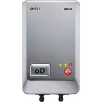
natural_image
White electronic device with black directional arrows indicating movement or flow (no visible text or symbols)natural_image
Close-up of a white electronic device with a digital display and 'Go' button, showing two black arrows pointing to the bottom (no text or symbols on the device itself)2 Safety and the environment....20
2.1. About this document....20
2.2. Ensure safety....21
2.3. Protecting the environment....21
3 Specifications 22
3.1. Use 22
3.2. Technical data 22
4 First steps 24
4.1. Releasing/securing data logger 24
4.2. Inserting batteries....25
4.3. Connecting data logger to PC....26
5 Display and control elements....27
5.1. Display....27
5.2. Key functions....28
6 Using the product....29
6.1. Programming data logger 29
6.2. Mounting wall bracket....29
6.3. Reading out data 29
7 Maintaining the product....30
7.1. Changing the batteries ....30
7.2. Cleaning the instrument....31
8 Tips and assistance....32
8.1. Questions and answers....32
8.2. Accessories and spare parts 32
2 Safety and the environment
2.1. About this document
Use
Please read this documentation through carefully and familiarize yourself with the product before putting it to use. Pay particular attention to the safety instructions and warning advice in order to prevent injuries and damage to the products.
Keep this document to hand so that you can refer to it when necessary.
Hand this documentation on to any subsequent users of the product.
Symbols and writing standards
| Representation | Explanation |
| Warning advice, risk level according to the signal word:Warning! Serious physical injury may occur.Caution! Slight physical injury or damage to the equipment may occur.> Implement the specified precautionary measures. | |
| i | Note: Basic or further information. |
| 1. ...2. ... | Action: more steps, the sequence must be followed. |
| > ... Action: a step or an optional step. | |
| - ... Result of an action. | |
| Menu Elements of the instrument, the instrument display or the program interface. | |
| [OK] Control keys of the instrument or buttons of the program interface. | |
| ... | ... Functions/paths within a menu. | |
| “...” | Example entries |
2.2. Ensure safety
Only operate the product properly, for its intended purpose and within the parameters specified in the technical data. Do not use any force.
Never use the instrument to measure on or near live parts.
Keep the read-out contacts on the rear of the data logger in particular away from live parts!
Carry out only the maintenance and repair work on this instrument that is described in the documentation. Follow the prescribed steps exactly. Use only original spare parts from Testo.
2.3. Protecting the environment
Dispose of faulty rechargeable batteries/spent batteries in accordance with the valid legal specifications.
At the end of its useful life, send the product to the separate collection for electric and electronic devices (observe local regulations) or return the product to Testo for disposal.
3 Specifications
3.1. Use
The testo 174 data loggers are used for storing and reading out individual readings and series of measurements.
Readings are measured and stored with the testo 174 and transmitted to the PC via the interface, where they can be read out and evaluated using the testo ComSoft software. The data logger can also be programmed individually via the software.
Examples of applications
testo 174T is ideally suited for temperature measurement in in refrigerators, freezers, cold rooms and cold shelves.
testo 174H monitors the climatic conditions, e.g. in warehouses, offices and in the manufacturing sector.
3.2. Technical data
testo 174T
| Characteristic Values | |
| Probe type Internal | NTC temperature sensor |
| Measuring range -30 to +70 °C | |
| Accuracy ± 0.5 °C (-30 to +70 °C) | |
| Resolution | 0.1 °C |
| Operating temperature | -30 to +70 °C |
| Storage temperature | -40 to +70 °C |
| Battery type 2 x 3 V | button cell (2 x CR 2032 lithium) |
| Life 500 days (15 min measuring cycle, +25 °C) | |
| Protection class IP65 | |
| Meas. cycle 1 min - | 24 h (can be selected) |
| Memory | 16,000 readings |
| Software can be used with Windows XP, Vista, Win7 | |
| Standards | 2004/108/EC, complies with the directives in accordance with the standard EN 12830 ^3 |
| Warranty | 24 months, warranty conditions: see website www.testo.com/warranty |
testo 174H
| Characteristic Values | |
| Probe type | NTC temperature sensor and internal capacitive humidity sensor |
| Measuring range | 0 to 100 % RH (not for condensing atmosphere4), -20 to +70 °C |
| Humidity accuracy | ± 3 % RH (2 % RH to 98 % RH) at +25 °C ± 0.03 % RH/K ± 1 digit |
| Temperature accuracy | ± 0.5 °C (-20 to +70 °C) |
| Resolution 0.1 % RH, 0.1 °C | |
| Operating temperature | -20 to +70 °C |
| Storage temperature | -40 to +70 °C |
| Battery type 2 x 3 V | button cell (2 x CR 2032 lithium) |
| Life 1 year (15 min measuring cycle, +25 °C) | |
| Protection class IP20 | |
| Meas. cycle 1 min - | 24 h (can be selected) |
| Memory 2 x 8000 readings | |
| Software can be used with Windows XP, Vista, Win7 | |
| Warranty 24 months, warranty conditions: see website www.testo.com/warranty | |
| EC Directive 2004/108/EC | |
4 First steps
4.1. Releasing/securing data logger

The data logger is delivered secured.
Releasing data logger
natural_image
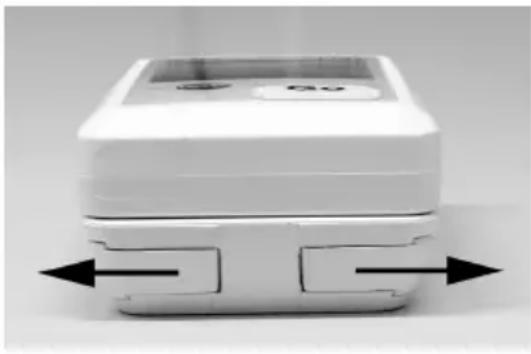
White plastic electronic device with black directional arrows indicating movement or flow (no text or symbols visible)- Push both locks on the bottom of the wall bracket outwards.
- Slide data logger out of the wall bracket.
Securing data logger
natural_image
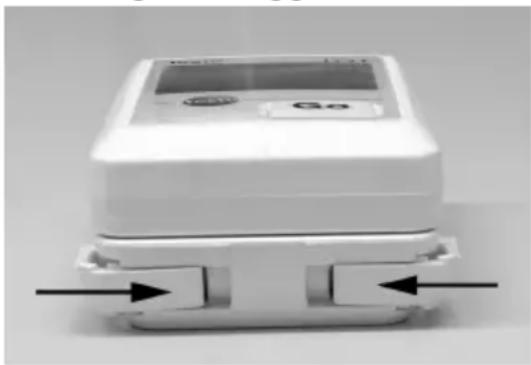
Close-up of a white electronic device with a display and control buttons, no visible text or symbols.- Slide data logger into the wall bracket.
- Push both locks on the bottom of the wall bracket inwards.
4.2. Inserting batteries
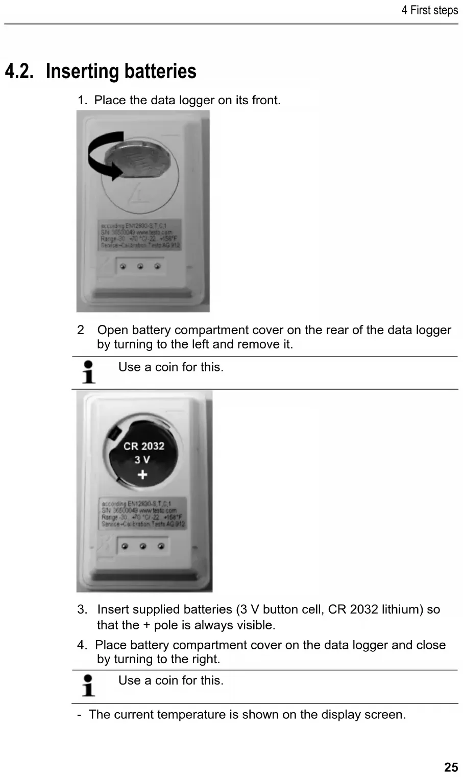
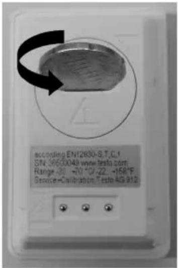
- Place the data logger on its front.
text_image
according EN12890-S.T.C.1 S/N 3650049 www.testo.com Range -30 ~70 °C/-22 ~458°F Service-Calibration Testp AIG 9122 Open battery compartment cover on the rear of the data logger by turning to the left and remove it.
i
Use a coin for this.
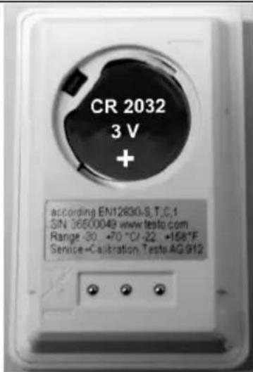
text_image
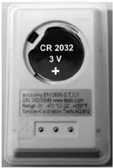
CR 2032 3 V + according EN12830-S.T.C.1 SIN 36500048 www.testo.com Range -30 +70 °C/-22 +158°F Service-Calibration Teste AG912-
Insert supplied batteries (3 V button cell, CR 2032 lithium) so that the + pole is always visible.
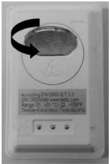
-
Place battery compartment cover on the data logger and close by turning to the right.
i
Use a coin for this.
- The current temperature is shown on the display screen.
4.3. Connecting data logger to PC
- Install testo ComSoft software.
The software is available in the Internet as a free download requiring registration: www.testo.com/download-center.
i The instructions for the installation and operation of the software can be found in the testo ComSoft instruction manual that is downloaded together with the software.
The software can be ordered on CD (article no. 0572 0580) if the download from the Internet is not desired.
-
Connect the connecting cable of the interface to a free USB interface on the PC.
-
Slide the data logger into the bracket of the interface.
-
Configure data logger, see separate testo ComSoft instruction manual.
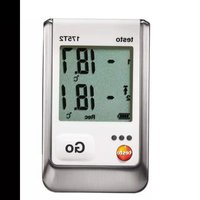
5 Display and control elements
5.1. Display
Depending on the operating status, various information may be shown in the display. A detailed depiction of the information that can be called up can be found in the quick instruction manual that is included with every data logger.
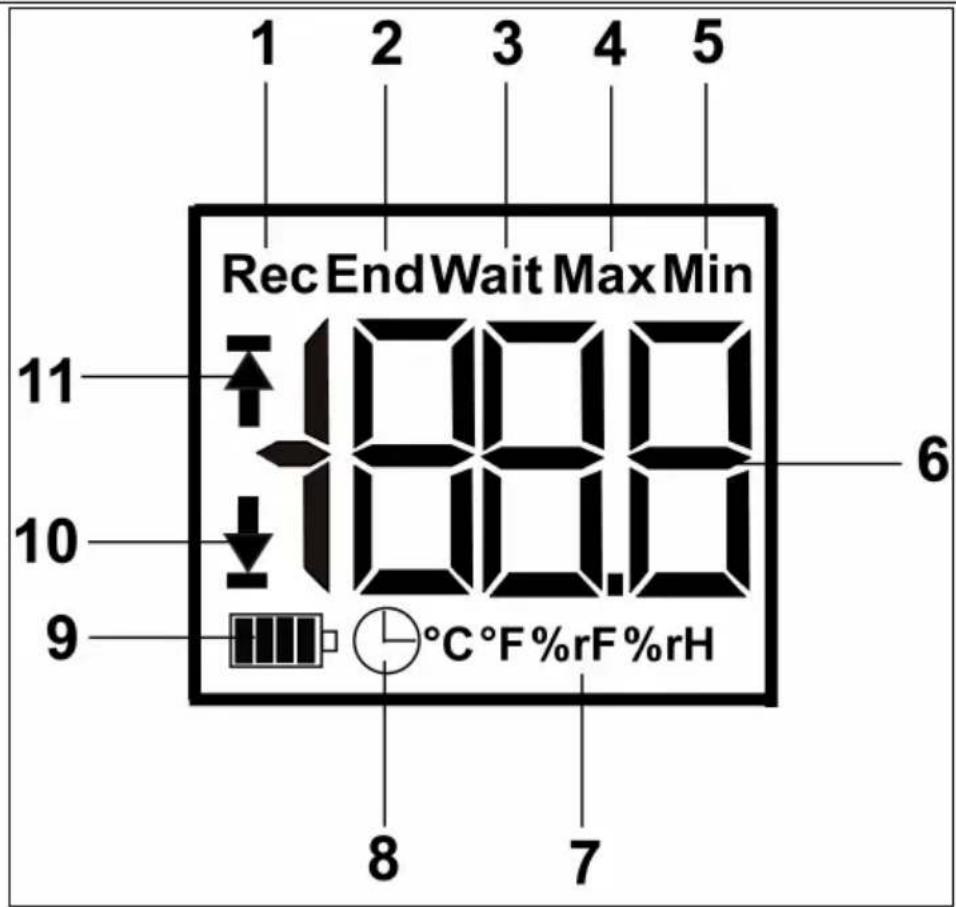
text_image
1 2 3 4 5 Rec End Wait Max Min 11 10 9 °C °F %rF %rH 6 8 71 Measurement program running
2 Measurement program over
3 Wait for start of measurement program
4 Highest saved reading
5 Lowest saved reading
6 Reading
7 Units
8 Start criterion Date/time programmed
9 Battery capacity
| Icon Capacity | |
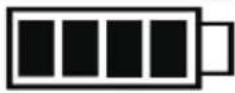 | 75-100% |
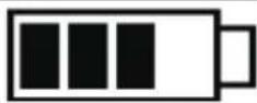 | 50-75% |
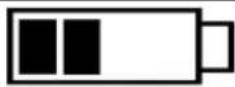 | 25-50% |
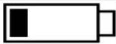 | 10-25% |
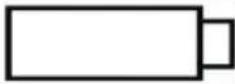 | <10% |
 | Battery empty (measurement program was stopped).> Read out data and change battery (see Changing the batteries page 30). |
10 Lower alarm value:
• Flashes: programmed alarm value is shown
- Lights up: programmed alarm value was undershot
11 Upper alarm value
• Flashes: programmed alarm value is shown
- Lights up: programmed alarm value was exceeded

The display speed of liquid crystal displays slows down at temperatures below 0 °C (approx. 2 seconds at -10 °C , approx. 6 seconds at -20 °C ) for technical reasons. This does not influence the measuring accuracy.
5.2. Key functions
√ Operating status Wait and start criterion Button start programmed.
Press and hold GO button approx. 3 seconds to start the measurement program.
- The measurement program starts and Rec appears in the display.
√ Operating status Wait:Press GO button in order to change between displays of the upper alarm value, lower alarm value, battery life and last reading.
- These are shown in the specified sequence in the display.
√ Operating status Rec or End:
Press GO button in order to change between displays of the highest saved reading, lowest saved reading, upper alarm value, lower alarm value, battery life and last reading.
- These are shown in the specified sequence in the display.
6 Using the product
6.1. Programming data logger
In order to adapt the programming of your data logger to your individual requirements, you require the testo ComSoft software. It is available in the Internet as a free download requiring registration www.testo.com/download-center.
i
The instructions for the installation and operation of the software can be found in the testo ComSoft instruction manual that is downloaded together with the software.
6.2. Mounting wall bracket
i
Mounting materials (e.g. screws, anchor plugs) are not included in the delivery.
√ Data logger is removed from the wall bracket (see Releasing/securing data logger page 24).
1. Position wall bracket at the desired location.
2. Using a pen or similar, mark the location for the fastening screw.
3. Prepare the fastening location for the attachment in accordance with the material (e.g. drill hole, insert anchor plug).
4. Fasten wall bracket using an appropriate screw.
6.3. Reading out data
The data logger is read out and the read-out data are processed further by means of the testo ComSoft software, see separate instruction manual.
7 Maintaining the product
7.1. Changing the batteries

The running measurement program is stopped when the battery is changed. The stored data are preserved, however.
- Read out stored data, see testo ComSoft software instruction manual.
√ If it is no longer possible to read out the stored data because the battery capacity is too low:Change batteries and then read out the stored data.
- Place the data logger on its front.
- Open battery cover on the rear of the data logger by turning to the left. Use a coin for this.
text_image
according EN12830-S.T.C.1 SN:3650049 www.testa.com Range-30 -470-10/-22:-158°F Service-Calibration Testp-AG 912- Remove empty batteries from the battery compartment.
- Insert two new batteries (3 V button cells, CR 2032 lithium) into the instrument so that the + pole is always visible.
text_image
CR 2032 3 V + according EN12830-S.T.C.1 SIN 36500049 www.testo.com Range -30: +70 °C/-22: +158°F Service-Calibration Testo AG 912i
Only use new branded batteries. If a partially used battery is inserted, the calculation of the battery capacity is not performed correctly.
- Place battery compartment cover on the battery compartment and close by turning to the right. Use a coin for this.
- The current reading is shown on the display.
i
The data logger must be reconfigured. To do so, the testo ComSoft software must be installed on the computer and a connection to the data logger must be set up (see Connecting data logger to PC page 26).
-
Slide the data logger into the bracket of the interface.
-
Start testo ComSoft software and create a connection to the data logger.
-
Reconfigure data logger or install the old stored configuration, see separate testo ComSoft instruction manual.
- The data logger is once again ready for use.
7.2. Cleaning the instrument
CAUTION
Damage to the sensor!
Ensure that no liquid enters the inside of the housing.
If the housing of the instrument is dirty, clean it with a damp cloth.
Do not use any aggressive cleaning agents or solvents! Weak household cleaning agents or soap suds can be used.
8 Tips and assistance
8.1. Questions and answers
| Question | Possible causes/solution |
| - - - -lights up in the display * | The sensor of the data logger is defective.> Contact your dealer or Testo Customer Service. |
* This is also shown in the display if a new measurement program is transferred from the PC to the data logger. It goes out again after approx. 8 seconds. In this case, there is no error!
If you have any questions, please contact your dealer or Testo Customer Service. The contact details can be found on the back of this document or on the Internet at www.testo.com/service-contact.
8.2. Accessories and spare parts
| Description Article no. | |
| testo 174H mini data logger, 2-channel, incl. wall bracket, battery (2 x CR 2032 lithium) and calibration protocol | 0572 6560 |
| testo 174T mini data logger, 1-channel, incl. wall bracket, battery (2 x CR 2032 lithium) and calibration protocol | 0572 1560 |
| USB interface for programming and reading out testo 174T and testo 174H loggers | 0572 0500 |
| testo ComSoft CD (if free download requiring registration from website is not desired) | 0572 0580 |
| Battery, 3 V button cell (CR 2032 lithium), please order 2 batteries per logger | 0515 0028 |
| ISO calibration certificate humidity, calibration points 11.3 % RH; 50.0 % RH; 75.3 % RH at +25 °C/+77 °F; per channel/instrument | 0520 0176 |
| ISO calibration certificate temperature, calibration points -18 °C; 0 °C; +60 °C; per channel/instrument | 0520 0151 |
1 Sommaire
1 Sommaire 33
natural_image
White electronic device with black arrows indicating directional flow or movement (no text or symbols visible)natural_image
Close-up of a white electronic device labeled 'Go' with directional arrows indicating flow or movement (no readable text beyond label)natural_image
White electronic device with black directional arrows indicating movement or flow (no text or symbols visible)natural_image
Close-up of a white electronic device with indicator lights and a 'Go' button, mounted on a base with two arrows pointing to the bottom (no visible text or symbols)natural_image
White electronic device with black arrows indicating directional flow or movement (no visible text or symbols)natural_image
White electronic device with a display and 'Go' button, mounted on a base with black arrows indicating direction (no visible text or symbols)natural_image
White electronic device with black arrows indicating directional flow or movement (no text or symbols visible)- Deslocar ambos os trincos na parte inferior do suporte de parede para fora.
- Retirar o data logger do suporte de parede.
natural_image
White electronic device with a display and 'Go' button, mounted on a base with directional arrows (no visible text or symbols)- Colocar o data logger no suporte de parede.
- Deslocar ambos os trincos na parte inferior do suporte de parede para dentro.
4.2. Colocar as pilhas
www.testo.com/service-contact.