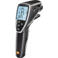
845 - Thermometer Testo - Free user manual and instructions
Find the device manual for free 845 Testo in PDF.


| Product Type | Infrared Thermometer |
| Model | 845 |
| Brand | Testo |
| Measurement Range | -30 °C to 650 °C |
| Accuracy | ±1.5 °C or ±1.5% of reading (whichever greater) |
| Resolution | 0.1 °C |
| Distance-to-Spot Ratio | 50:1 |
| Response Time | < 300 ms |
| Emissivity | Adjustable from 0.10 to 1.00 |
| Laser Sight | Class 2 laser, < 1 mW, 630-670 nm |
| Display | Backlit LCD with dual reading |
| Data Hold | Yes |
| Auto-Off | After 15 seconds of inactivity |
| Power Supply | 2 x AA batteries (1.5 V) |
| Battery Life | Approx. 100 hours continuous use |
| Dimensions | 190 x 75 x 38 mm |
| Weight | 200 g (including batteries) |
| Operating Temperature | 0 °C to 50 °C |
| Storage Temperature | -20 °C to 60 °C |
| Cleaning | Wipe lens with soft cloth; clean housing with damp cloth |
| Safety | Laser class 2; avoid direct eye exposure |
| Spare Parts / Repairability | Battery cover, lens cap; service by authorized Testo centers |
| Certification | CE, FDA |
Frequently Asked Questions - 845 Testo
User questions about 845 Testo
0 question about this device. Answer the ones you know or ask your own.
Ask a new question about this device
Download the instructions for your Thermometer in PDF format for free! Find your manual 845 - Testo and take your electronic device back in hand. On this page are published all the documents necessary for the use of your device. 845 by Testo.
USER MANUAL 845 Testo
- Safety instructions....3
- Intended purpose ....4
- Product description....5
3.1 Display and operating elements ....5
3.2 Interfaces ......6
3.3 Voltage supply 6
- Commissioning 7
- Operation 7
5.1 Connecting probes....7
5.2 Switching on / off 8
- Setting instrument 8
6.1 Instrument configuration....8
6.2 Measurement configuration ....10
6.3 Degree of emission 13
6.4 Storing measurement protocols ....13
6.5 Printing measurement protocols....14
6.6 Printing current readings ....14
6.7 Reading memory full .....14
- Programming 15
7.1 Installing software 15
7.2 Connecting testo 845 to a PC ....15
7.3 Setting up connection ....15
7.4 Opening connection....16
7.5 Programming testo 845 .....16
7.6 Disconnecting ....17
- Measuring 18
-
Care and maintenance .....21
-
Questions and answers....22
- Technical data 23
- Accessories / spare parts .....24
General information
This chapter provides important information on the use of this documentation.
This documentation contains information which must be observed in order to ensure safe and efficient application of the product.
Read this document carefully and familiarize yourself with the operation of the product before putting it to use. Keep this document close to hand in order to be able to refer to it when necessary.
Symbols
| Symbol Meaning Comments | ||
 | Warning! Read the warning carefully and take the safety measures described!Serious injury can occur if the safety measures are not taken. | |
| Warning! | ||
 | Attention! Read the warning carefully and take the safety measures described!Light injury or object damage can occur if the safety measures are not taken. | |
| Caution! | ||
| i | Information Provides useful tips and information. | |
| ➢, 1, 2 | Handling objective | Describes the objective reached by the following handling steps.Observe the order for numbered handling objectives |
| √ Prerequisite Prerequisite must be fulfilled in order for a step to be carried out as described | ||
| ➢, 1, 2, ... | (Handling) step | Carry out handling steps. Observe the order for numbered handling steps! |
| Text Display text | Text appears in instrument display. | |
| Taste | Operating key | Press key. |
| Function key | Press key. | |
| - | Result | Describes the result of a (handling) step previously carried out. |
| → | Cross reference | Reference to further or more detailed information. |
1. Safety instructions
This chapter describes general rules which must be observed in order to ensure safe use of the product.
Avoiding damage and injury
Do not use the measuring instrument on or close to live components.
Never store the instrument together with solvents, do not use dessicants.
Infrared measurement: When measuring live components, observe the necessary safety distance.
Product safety / Preserving warranty claim
Use the measuring instrument only within the parameters given in the Technical Data.
Use the instrument only for the purpose for which it is intended. Do not use force.
Do not subject to electromagnetic radiation (microwaves, induction heating), static electricity, heat or extreme temperature fluctuations.
Do not subject handles and wires to temperatures over 70 °C if these are not expressly approved for higher temperatures. Temperature information on probes/sensors refers only to the measuring range of the sensors.
Open the measuring instrument for maintenance or repair purposes only if this is expressly described in the documentation.
Carry out only maintenance and repair work which is described in the documentation. When doing so, observe the steps prescribed. For safety reasons, use only original Testo replacement parts.
Laser radiation! Do not look into the laser beam. Laser class 2.
Correct disposal
Hand in defective rechargeable batteries / empty batteries to the correct collecting points.
Send the product back to Testo if it is no longer to be used. We will dispose of it ecologically.
2. Intended purpose
This chapter describes the areas of application for which the instrument is intended.
Use the product only for the areas for which it was designed. In case of doubt please consult Testo.
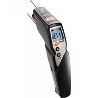
The testo 845 is a compact infrared thermometer for the non-contact measurement of surface temperatures. Using connected probes, additional measurements can be made with the testo 845.
The product may not be used in the following areas:
- In areas where there is a danger of explosion.
- For diagnostic measurements in medicine.
For reasons of Patent Law, the testo 845 may not be used in Great Britain in combination with the humidity module.
3. Product description
This chapter provides an overview of the components of the product and their functions.
3.1 Display and operating elements
Overview

① Infrared sensor
② Humidity module
(standard with 0563 8451; retrofittable for 0563 8450)
③ Measurement trigger
④ Battery compartment
⑤ IR diode for printer
⑥ Display
⑦ Slide switch
⑧ Operating buttons
⑨ Probe socket
⑩ USB interface
Button functions
Button Functions


Change configuration settings

Printout of values on Testo IR printer Instrument configuration: activate adjustment

Store a measurement protocol Measurement and instrument configuration menu: apply values and jump to next setting menu

Switch between possible display images

Measurement and instrument configuration menu: change setting values
3. Product description
Display
Display Functions

+ °C/°F Temperature reading IR

+ °C/°F Temperature reading contact probe

+ % Ambient humidity value in % relative humidity

+ °C/°F Ambient temperature reading

+ °Ctd Ambient dewpoint

+ °C Δtd Dewpoint distance
3.2 Interfaces
USB interface
The mains unit (accessory) for the voltage supply of the instrument can be connected via the USB interface on the underside of the instrument.
Measurement / instrument data can be exchanged with a PC via the USB interface. The measuring instrument is a HighPower instrument, an additional USB-hub may be necessary!
Probe socket(s)
Plug-in thermocouple probes type K can be connected via the probe socket on the underside of the instrument.
3.3 Voltage supply
The voltage supply is provided by two mignon batteries (included in delivery) or rechargeable batteries or via a USB mains unit (accessories). Rechargeable batteries cannot be charged in the instrument.
4. Commissioning
This chapter describes the handling steps necessary for commissioning the instrument.
➢ Batteries/rechargeable batteries
1 Open the battery compartment cover in the handle.
2 Fit batteries / rechargeable batteries (2 x Mignon) into the battery compartment. Observe polarity!
3 Close the battery compartment cover.
5. Operation
This chapter describes the handling steps which are carried out often when using the instrument
5.1 Connecting probes
Plug-in probes
Plug-in probes must be connected before switching on the measuring instrument in order for them to be recognized by the instrument.
Insert the connection plug of the probe into the probe socket of the instrument.
Connecting humidity module 0636 9784
Placeholder sensoranbau

Open the cover carefully using a suitable tool.
Remove the cover from the connection plug.
Connect the humidity module to the plug and push into the housing.
5.2 Switching on / off
▶ Switching instrument on:
Press measurement trigger and hold down - The measurement display is opened: The current measurement value and the min. / max. values are displayed
▶ Switching instrument off:
The instrument switches off automatically after 10 s if no button is pressed.
6. Setting instrument
This chapter describes the handling steps required to adapt the measuring instrument for special measurement tasks.
6.1 Instrument configuration
The basic settings for the measuring instrument are carried out in the configuration menu.
The configuration mode can be exited at any time. To do this, press Instrument switches to measurement display. Changes already applied with the configuration mode are saved.
1 Opening configuration mode:
√ The instrument is switched on and is in measurement display.
Hold down measurement trigger and briefly press Mode : °C is displayed. - The instrument is now in configuration mode.
2 Setting ttemperature:
√ The configuration mode is open, °C is displayed.
Set °C/°F with ▲ / ▼ °C/°F and confirm with 📄.
The setting is applied with and the instrument jumps to the next function.
Continue with handling objective SETTING DISPLAY ILLUMINATION.
3 Setting display illumination:
√ The configuration menu is open, °C is displayed.
Go to menu Display illumination On/Off with 📄.
Select the desired option with △ and confirm with .
Continue with SET CONTINUOUS MEASUREMENT.
4 Setting continuous measurement (see also Chapter 8. Measuring):
√ The configuration mode is open, °C is displayed.
Go to menu Auto on/off with (2x).
Select the desired option with △ and confirm with .
i The laser function is not available during continuous measurement.
Continue with handling objective SETTING LASER.
5 Setting llaser:
√ The configuration mode is open, °C is displayed.
Go to menu Laser on/off with Ⓐ (3x).
Select the desired option with △ and confirm with .
Continue with handling objective SETTING DATE.
6 Setting ddate:
√ The configuration mode is open, °C is displayed.
Go to menu Setting date with ☑ (4x).
Setting day: Select the desired day with △ and confirm with .
Setting month: Select the desired month with △ and ▽
confirm with
Setting year: Select the desired year with ▲/▼ and confirm with
→ Continue with handling objective SETTING TIME.
7 Setting ttime:
√ The configuration mode is open, °C is displayed.
Go to menu Setting time with ☑ (7x).
Setting hour: Select the desired hour with ▲ /▼ and confirm with 📄
Setting minute: Select the desired minute with ▲ /▼ and confirm with 📁
Continue with handling objective ADJUSTING HUMIDITY MODULE AT 11.3 AND 75.3 %RH (only with integrated humidity module).
8 Adjusting humidity module at 11.3 and 75.3 %rF (only with integrated humidity module):
Before checking or calibrating, the probe and the checking and calibrating set should be stored at a constant temperature range (+20 to +30 °C) for approx. 12 hours.
To calibrate the humidity module in the test container, carefully pull the humidity probe out of the testo 845. The test container can be stored horizontally during calibration.
- The minimum assimilation time for checks with the probe inserted into the test container is 15 minutes.
- A minimum assimilation time of one hour is recommended for calibration.
- Keep away from all external interference (direct heat radiation, draughts etc.).
- Observe directions for use “Control and humidity adjustment set) (Order No. 0973 1820).
√ The configuration mode is open, °C is displayed.
Go to menu Adjusting humidity module at 11.3 and 75.3 %RH with 📋.
Activate adjustment with 📄. The corrected value is displayed for 3 s.
Continue with handling objective FACTORY SETTINGS.
9 Factory ssettings:
√ The configuration mode is open, °C is displayed.
Go to menu Factory settings (reset) with 📄.
The values return to the delivery status.
Select the desired option with ▲ / ▼ and confirm with □.
Return to main menu.
6.2 Measurement configuration
In the configuration menu, settings for measurement are carried out.
The configuration mode can be exited at any time. To do this, press Mode. Instrument switches to measurement display. Changes already applied with ☑ in the configuration mode are saved.
1 Opening configuration mode:
√ The instrument is switched on and is in measurement display.
Press Mode drücken.
- The instrument is now in configuration mode.
2 Setting degree of emission (E):
√ The configuration mode is open.
Set value with ▲ and confirm with .
Continue with SELECTION OF ALARM VALUE TO BE MONITORED.
3 Selection of alarm value to be monitored (dtd, Ir, rH Surface):
√ The configuration mode is open.
Select the desired option with ▲/▼ and confirm with
→ Continue with handling objective SETTING UPPER LIMIT VALUE (IR). or
→ Continue with handling objective SETTING LIMIT VALUE ΔTD or
Continue with handling objective SETTING LIMIT VALUE RHSI.
4 Setting upper limit value (Ir):
√ The configuration mode is open.
Select upper limit value with ▲ and confirm with .
If the upper limit value is exceeded, the max. value is displayed in the top line (symbol for exceeded upper limit value appears). The IR temperature is displayed as the main value. The corresponding limit/alarm value is displayed in the lower line. The alarm symbol appears. If an acoustic alarm has been selected, it sounds. If the value drops back under the limit value, the instrument returns to the display previously shown.
Continue with SETTING LOWER LIMIT VALUE (IR).
5 Setting lower limit value (Ir):
√ The configuration mode is open.
Select lower limit value with ▲ and confirm with .
If the lower limit value is exceeded, the max. value is displayed in the top line (symbol for exceeded lower limit value appears). The IR temperature is displayed as the main value. The corresponding limit/alarm value is displayed in the lower line. The alarm symbol appears. If an acoustic alarm has been selected, it sounds. If the value climbs back over the limit value, the instrument returns to the display previously shown.
Continue with handling objective AUDIBLE ALARM ON/OFF.
6 Setting limit value (dtd) (only in combination with the humidity module):
√ The configuration mode is open
Set the limit value with △ and confirm with .
When monitoring dewpoint distance, only one limit value can be selected. If the set limit value is exceeded, the limit value is displayed in the top line. The current dewpoint distance is displayed as the main value. The min. value is displayed in the lower line. The alarm symbol flashes. If an acoustic alarm has been selected, it sounds. If the value climbs back over the limit value, the instrument returns to the display previously shown.
Continue with AUDIBLE ALARM ON/OFF.
7 Setting limit value (rH Surface)(only in combination with humidity module):
√ The configuration mode is open.
Select limit value with ▲ and ▽ confirm with .
For surface moisture, only one limit value can be selected. If the set limit value is exceeded, the limit value is displayed in the top line. The current surface moisture is displayed as the main value. The min. value is displayed in the lower line. The alarm symbol flashes. If an acoustic alarm has been selected, it sounds. If the value climbs back over the limit value, the instrument returns to the display previously shown.
Continue with handling objective AUDIBLE ALARM ON/OFF.
8 Audible alarm (BEEP On/OFF):
√ The configuration mode is open.
Select the desired option with ▲ and ▼ confirm with .
Continue with DELETE MEMORY YES/NO.
9 Delete memory yes/no (dEL 0n/OFF):
√ The configuration mode is open.
Select the desired option with ▲ and ▼ confirm with .
Return to measurement menu.
i DELETE MEMORY deletes the entire contents of the memory.
6.3 Degree of emission
Materials have different degrees of emission, i.e. they produce different quantities of electromagnetic radiation. The degree of emission of the testo 845 is set at 0.95 ex-works. This is optimal for measurements of non-metals, plastics and food (paper, ceramics, plaster, wood, paints and lacquers).
Because of their low or inconsistent degrees of emission, bright metals and metal oxides have only limited suitability for IR measurements.
▶ Apply emission-enhancing coatings such as paint or emission adhesive tape (Order No. 0554 0051) to the object to be measured. If this is not possible, measure with a contact thermometer.
Degree of emission table for important materials (typical values)
| Material (Temperature) ε | Material (Temperature) ε | ||
| Aluminium, bright rolled (170°C) | 0,04 | Cooling element, black anodized (50°C) 0,98 | |
| Cotton (20°C) | 0,77 | Copper, slightly oxidized (20°C) 0,04 | |
| Concrete (25°C) | 0,93 | Copper, oxidized (130°C) 0,76 | |
| Ice, smooth (0°C) | 0,97 | Plastics: PE, PP, PVC (20°C) 0,94 | |
| Iron, sanded (20°C) | 0,24 | Brass, oxidized (200°C) 0,61 | |
| Iron with casting skin (100°C) | 0,80 | Paper (20°C) 0,97 | |
| Iron with rolling skin (20°C) | 0,77 | Porcelain (20°C) 0,92 | |
| Plaster (20°C) | 0,90 | Black paint, matt (80°C) 0,97 | |
| Glass (90°C) | 0,94 | Steel, heat-treated surface (200°C) 0,52 | |
| Rubber, hard (23°C) | 0,94 | Steel, oxidized (200°C) 0,79 | |
| Rubber, soft grey (23°C) 0,89 | Clay, fired (70°C) | 0,91 | |
| Wood (70°C) | 0,94 | Transformer lacquer (70°C) 0,94 | |
| Cork (20°C) | 0,70 | Bricks, mortar, plaster (20°C) | 0,93 |
6.4 Storing measurement protocols
To store a measurement protocol, the button must be pressed. The instrument can be in measurement or HOLD mode. The main value continues to be displayed during storage. The current protocol number is displayed in the lower line. The storage symbol +M is additionally displayed. 90 measurement protocols can be displayed.
6.5 Printing measurement protocols
In this chapter, the printing of measurement protocols is explained
1 Printing measurement protocols:
√ The instrument is in measurement display (Hold mode).
Hold down and press. C up memory menu.
Select stored measurement protocol with ▲ and confirm with . Measurement protocol values are displayed.

View further stored measurement protocols with ⚠️. ⬇
Start printout with
Return to memory menu with Mode
i The IR diode is situated on the front of the testo 845. Point the testo 845 at the printer.
i Return to measurement menu with Mode
The configuration menu can be exited at any time. To do this, press . Instrument switches to measurement display. Changes already carried out in the configuration menu are stored.
6.6 Printing current readings
In this chapter, the printing of current readings is explained
1 Printing current values:
√ The instrument is in measurement display (Hold mode).
Start printout with
6.7 Reading memory full
When 90 measurement protocols have been stored, FULL is displayed. Delete reading memory as required.
7. Programming
This chapter describes the handling steps necessary to create measurement programmes.
7.1 Installing software
In order to adapt the programming of the testo 845 to your individual needs, you require a PC in which the software testo ComSoft (included in delivery) and the USB driver have been installed. You will find the instructions for the installation and operation of the software and the USB driver in the instruction manuals for testo ComSoft and the USB driver.
After successfully installing the software, connecttesto 845 to the PC.
7.2 Connecting testo 845 to a PC
Connect the USB connection cable to your PC.
Connect the USB connection cable to the testo 845.
Start the software testo ComSoft.
7.3 Setting up connection
Start softwaretesto CComSoft
Select the functionAutodetect in the menu bar Instrument. The window Autodetect opens.
The connection to the testo 845 found is set up automatically and the name of the connection appears in Archive.
or
Select the function New device in the menu barInstrument. The window New device setup wizard opens.
Select testo 845 in the instrument choice and click on Next.
Enter the name of the connection and click onNext.
7.4 Opening connection
Double-click on the connection to be opened in the window Archive.
If a measurement protocol has been stored in the testo 845, the protocol symbol and the short title of the protocol appear under the opened connection.
Using one connection for several testo 845
You can connect different testo 845 via one connection. When the testo 845 is changed, the connection must be broken and then re-made for the new testo 845, otherwise the software will not be able to identify it.
Read any existing data out of the testo 845 before programming (see instruction manual for the software testo ComSoft).
Select the function device control in the menu bar Instrument.
This function is only active when the name of the connection is marked in colour. If this is not the case:
First click on the name of the connection and thenInstrument> device control.
- The window for programming the testo 845 opens.
7.5.1 Programming testo 845
Instrument
Date and time:
The set date and time of the testo 845 are displayed.
To synchronize the date and time with the clock in your PC, select synchronize.
Options
Set degree of emission. Mark displayed value and alter.
Set unit °C/°F.Activate/deactivate laser, continuous measurement and illumination.
Enter headers for printer.
Measurement configuration
Limit values (Factory setting)
| Infrared Dew point distance Surface moisture |
| upper limit value 950.0 - -20.0 |
| lower limit value 10.0 -40.0 - |
Activate/deactivate Audible alarm
Reset
Activate/deactivate Allow store deletion
- Delete memory.
Memory contents are deleted.
- Factory settings
Instrument settings are returned to factory settings
Humidity module adjustment
PressAdjustment humidity module button.
The window Dialog opens.
To adjust press the buttons 11.3% and 75.3%.
Close window
7.5.2 Ending programming
Click on Apply to apply the programming carried out to testo 845.
7.6 Disconnecting
In the windowArchive, click on the connection you want to disconnect with the right-hand mouse key.
Select Close.
The connection to testo 845 is disconnected.
8. Measuring
This chapter describes the handling steps required to carry out measurements with the product.
Measurement point, distance
Depending on the distance between the measuring instrument and the object to be measured, a certain measurement point is recorded.
Measurement optics (Ratio distance : measuring point)
Close focus measurement

Set close focus measurement in the instrument.
The symbol is shown in the display

If a measurement distance > 250 mm, switch over to far field measurement.
Far field measurement
Set far field measurement in the instrument.
The symbols shown in the display.

Carrying out measurements:
i Scrolling through the measurement menus is possible with the measurement trigger pressed down as well as in the Hold mode.
Hold mmode
In the hold mode the last recorded measurement readings are frozen.
Continuous measurement switched off
The instrument measures as long as the measurement trigger is pressed. The instrument goes into Hold mode when the measurement trigger is released. The Hold mode is exited as soon as the measurement trigger is pressed again. The max. and min. values are reset.
Continuous measurement switched on
The measuring instrument measures without the use of the measurement trigger. The Hold mode is activated by pressing the measurement trigger. The instrument continues to measure as soon as the measurement trigger is pressed again. The max. and min. values are reset.
1 IR measurement ( )
√ The instrument is switched on and is in measurement display. Max and Min are activated.
i IR measurement is an optical measurement. Keep the lens clean. Do not measure if the lens is fogged.
2 IR measurement and TC probes ( / — )
i Measurement menu only active when TC probe is plugged in.
Select the desired option with △ ▽
Setting degree of emission
√ Instrument is in Hold mode.
Set degree of emission with and /.
During setting, must be held down.
The IR temperature value is updated with every alteration of the emission value. The degree of emission of surfaces can thus be determined.
Observe minimum penetration depth for immersion / penetration probes: 10 x probe diameter
Avoid applications in aggressive acids or alkalis.
Do not make measurements on sharp edges with cross-band surface probes.
Display:
- Max. value, 2. IR temperature, 3. Min. value
3 IR measurement and humidity module (/ ■)
i Measurement menu only active when humidity probe is plugged in.
Select the desired display mode with △ ▽
Display:1. Humidity, 2. IR-Temperature, 3. Dewpoint
4 Temperature and humidity module ( ■ )
i Measurement menu only active when humidity probe is plugged in.
Select the desired display mode with △ ▽
Display:1. Humidity, 2. IR-Temperature, 3. Dewpoint
5 Dewpoint distance ( ■ )
i Measurement menu only active when humidity probe is plugged in.
Display of dewpoint distance incl. max. and min. values.
Select the desired display mode with △ ▽
Display:1. Max. value, 2. Dewpoint distance, 3. Min. value
6 Surface mmoisture
Walls and ceilings in danger of mould can be localized based on the surface moisture. The surface moisture is measured from 0 to 1.0 (0 = dry, 1 = very damp). According to DIN EN ISO 13788, the danger of mould on surfaces exists if the moisture level rises above 0.8 over several days. The testo 845 calculates the surface moisture from the surface temperature (IR) and the dewpoint of the air.
i Measurement menu only active when humidity probe is plugged in.
Display of surface moisture incl. max. and min. values.
Select the desired display mode with △ ▽
Display:1. Max value, 2. Calculated surface moisture, 3. Min. value
9. Care and maintenance
This chapter describes the handling steps which contribute to maintaining the functionality of the product and to extending its useful life.
▶ Cleaning the housing:
If dirty, clean the housing with a damp cloth (soap solution). Do not use any aggressive cleaning products or solvents!
➢ Changing battery / rechargeable battery:


√The instrument is switched off.
1 Open the battery compartment in the handle.
2 Remove empty batteries / rechargeable batteries
Pull the battery removal strip or
push on the upper part of the battery with your finger. The battery is released.
3 Remove batteries and replace with new batteries. Observe polarity!
4 ReClose battery compartment.
10. Questions and answers
Question Possible causes Possible solution
| is lit. - Battery empty. Change battery. | |
| Instrument cannot be - Battery empty. Change battery. switched on. | |
| Lasers light up briefly - Battery empty. Change battery. after switching on, then go out. | |
| Measurement value - Measurement value outside - - - - lights up. measuring range. | |
| Display FULL appears - Measurement protocol Delete memory memory full | |
| Err EE or Err HSEE Send instrument to Testo Customer Services appears |
If we were not able to answer your question, please contact your dealer or Testo Customer Service. For contact data, see back of this document or web page www.testo.com/service-contact
11. Technical data
Description testo 845
| Measurement parameter Temperature (°C / °F) | |
| Measurement value recorder Infrared sensor | |
| Measuring range • IR °C -35°C to +950°C | • Humidity module 0 to 100%RH0 to +50°C-20 to +50°C td• Contact °C -35 to +950 °C |
| Resolution 0.1°C (°C measurement parameters) | 0.1%RH (humidity)0.1°C td (dewpoint) |
| Accuracy IR (at 23°C) +/- 1 digit +/- 2.5°C (-35 to -20.1°C) | +/-1.5°C (-20 to +19.9°C)+/-0.75°C (+20.0 to +99.9°C)+/-0.75% of m.v.(+100 to +950°C) |
| Accuracy °C contact (Type K) +/- 1 digit +/- 0.75°C (-35 to +75°C) | +/-1 % of m.v. (+75.1 to +950°C) |
| Accuracy humidity module +/- 1 digit +/- 2% RH (2 to 98% RH) | +/-0.5 °C (+10 to +40°C)+/-1.0 °C (remaining range) |
| Emission factor adjustable 0.1 to 1.0 | |
| Wavelength 8 to14 μm | |
| Switchable distance ratio Far field: 75:1 (16mm, distance 1200mm) | Close focus: 1mm, distance 70mm |
| Probe integrated infrared | |
| Measurement rate | t95: 150 msScanning max./min./Alarm: 100 ms |
| Application temperature | -20°C to +50°C |
| Storage temperature | -40°C to +70°C |
| Battery type | 2 x AA AlMn |
| Battery life | 25 h (without laser)10 h (with laser without backlight)5 h (with laser and 50% backlight) |
| Battery exchange | by user |
| Housing | ABS (black, grey), metal cover |
| Display | three-line with backlight |
| Dimensions testo 845 in mm (LBH) | 155 x 58 x 195 |
| Dimensions case in mm (LBH) | 405 x 340 x 93 |
| Weight testo 845 without humidity module | 455 g |
| Weight testo 845 with humidity module | 465 g |
| Weight instrument and case | 2700 g |
| EU guideline | 2004/108/EEC |
| Sensitivity IR measurement: | ±2°C (±3.6°F) for 640 MHz to 680 MHz in 2.5 V/m field.(+20.0...+99.9°C) |
| Interference: | trade-typical limit according to EN 61326-1 |
12. Accessories / spare parts
This chapter describes important accessories and spare parts for the instrument
| Description Order no. | |
| Retrofittable humidity module 0636 9784 | |
| Surface probe with sprung TC band, short-term up to +500 °C, TC Type K 0602 0393 | |
| Surface probe with sprung TC band, short-term up to +500 °C, TC Type K, angled 0602 0993 | |
| Waterproof surface probe, TC Type K 0602 0693 | |
| Robust air probe, TC Type K 0602 1793 | |
| Testo report printer with wireless IRDA and infrared interface 0554 0547 | |
| Spare thermal paper for printer (6 rolls) 0554 0569 | |
| Spare thermal paper for printer (6 rolls), long-term legible (10 years) 0554 0568 | |
| External charger incl. 4 Ni.MH rechargeable batteries 300 mA, 50/60 Hz, 12 VA/instrument 0554 0610 | |
| Mains unit, 5 VDC/500 mA 0554 0447 | |
| Control and humidity adjustment set 11.3 %RH / 75.3 %RH 0554 0660 | |
| Adhesive tape for polished surfaces, =0.93 , heat-proof up to +300 °C | 0554 0051 |
| Silicone heat-conducting paste (14g) Tmax = +260 °C 0554 0004 | |
| ISO calibration certificate, calibration points +60 °C, +120 °C, +180 °C | 0520 0002 |
| ISO calibration certificate, calibration points -18 °C, 0 °C, +60 °C | 0520 0401 |
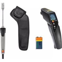
A complete list of all accessories and spare parts can be found in the product catalogues and brochures or on the internet at: www.testo.com

- GENERAL INFORMATION
- SAFETY INSTRUCTIONS
- AVOIDING DAMAGE AND INJURY
- PRODUCT SAFETY / PRESERVING WARRANTY CLAIM
- CORRECT DISPOSAL
- INTENDED PURPOSE
- PRODUCT DESCRIPTION
- 3.1 DISPLAY AND OPERATING ELEMENTS
- DISPLAY
- DISPLAY FUNCTIONS
- 3.2 INTERFACES
- USB INTERFACE
- PROBE SOCKET(S)
- 3.3 VOLTAGE SUPPLY
- COMMISSIONING
- OPERATION
- 5.1 CONNECTING PROBES
- PLUG-IN PROBES
- CONNECTING HUMIDITY MODULE 0636 9784
- 5.2 SWITCHING ON / OFF
- SETTING INSTRUMENT
- 6.1 INSTRUMENT CONFIGURATION
- 6.2 MEASUREMENT CONFIGURATION
- 6.3 DEGREE OF EMISSION
- 6.4 STORING MEASUREMENT PROTOCOLS
- 6.5 PRINTING MEASUREMENT PROTOCOLS
- 6.6 PRINTING CURRENT READINGS
- 6.7 READING MEMORY FULL
- PROGRAMMING
- 7.1 INSTALLING SOFTWARE
- 7.2 CONNECTING TESTO 845 TO A PC
- 7.3 SETTING UP CONNECTION
- 7.4 OPENING CONNECTION
- 7.5.1 PROGRAMMING TESTO 845
- OPTIONS
- RESET
- 7.5.2 ENDING PROGRAMMING
- 7.6 DISCONNECTING
- MEASURING
- 3 IR MEASUREMENT AND HUMIDITY MODULE (/ ■)
- 4 TEMPERATURE AND HUMIDITY MODULE ( ■ )
- 5 DEWPOINT DISTANCE ( ■ )
- 6 SURFACE MMOISTURE
- CARE AND MAINTENANCE
- QUESTIONS AND ANSWERS
- TECHNICAL DATA
- ACCESSORIES / SPARE PARTS
Brand : Testo
Model : 845
Category : Thermometer