Codix 534 - Measuring equipment Kübler - Free user manual and instructions
Find the device manual for free Codix 534 Kübler in PDF.
User questions about Codix 534 Kübler
0 question about this device. Answer the ones you know or ask your own.
Ask a new question about this device
Download the instructions for your Measuring equipment in PDF format for free! Find your manual Codix 534 - Kübler and take your electronic device back in hand. On this page are published all the documents necessary for the use of your device. Codix 534 by Kübler.
USER MANUAL Codix 534 Kübler
Bestellschlüssel: 6.534.012.300
line
| State | Current (I [mA]) | Voltage (U [V]) | |---|---|---| | -19999 | 0 | 0 | | 99999 | 0 | 0 |Order code: 6.534.012.300
1.1 Safety instructions and warnings
Use this display only
text_image
- in compliance with its intended purpose - if its technical condition is perfect - in accordance with the operating instructions and the general safety provisions.1.2 General safety instructions and warnings
- Before carrying out installation or maintenance work, make sure that the device is disconnected from the power supply.
- Use this digital display only in compliance with its intended purpose: if its technical condition is perfect and in accordance with the operating instructions and the general safety provisions.
- Comply with the country and application-specific provisions
- This digital display is not suitable for use in areas with explosion protection and for areas excluded in EN 61010 part 1.
- This digital display must only be operated when properly mounted in a panel in accordance with the section "Technical Data".
- The device must compulsorily be protected with approved external fuses. The value of these fuses can be found in the technical information.
1.3 Use according to the intended purpose
This digital display may only be operated as a built-in device. The application area for this display device lies in industrial processes and controls, in the fields of manufacturing lines for the metal, wood, plastics, paper, glass, textile and other like industries. Over-voltages at the terminals of the device must be kept within the limits of Over-voltage Category II. If the digital display is used to monitor machines or processes in which, in the event of a failure of the display or an error made by the operator, there
might be the risk of damaging the machine or causing an accident to the operators, it is your responsibility to take the appropriate safety measures.
1.4 Description
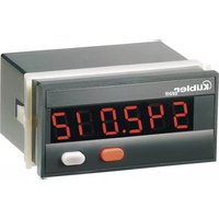
• Digital 5-digit display with analog inputs
- Easily readable, bright 8 mm high LED display
- Display range from -19999 to 99 999 with leading zero blanking and programmable decimal point
- The functions and operating parameters are programmed by means of the two setting keys.
Operator guidance on the display during the programming routine
- The following parameters are programmable:
Measuring range
Measuring time
Decimal point measured value
Minimum input signal
Value to be displayed for the
lowest input signal
Maximum input signal
Value to be displayed for the
highest input signal
Minimum value display yes/no
Minimum value reset
Maximum value display yes/no
Maximum value reset
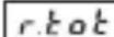
Totalizer yes/no
Decimal point totalizer
Multiplication factor totalizer
Scaling totalizer
Totalizer reset
2. Inputs
Latch/Reset (Terminal 4)
Static input for display storage. If it is activated (pnp) with a 4...30 V DC input signal, the current measuring value is retained on the display until this input is released or its signal level sinks below 2 V DC. The determination of the minimum and maximum value continues in the background. If an electrical reset is programmed for MIN, MAX, or for the Totalizer function, the function of the input changes to that of a reset input. It is therefore no longer possible to perform a Latch.
Current input (Terminal 5)
Analog current measurement input with reverse polarity protection and current limitation to 50 mA. The signal line carrying the analog + signal must be connected here.

To prevent interference signals due to the power supply, this input is galvanically isolated. Therefore, the most negative signal line must be connected to the analog reference ground input for measurement.
Analog GND (Terminal 6)
Analog reference input.
If no galvanic separation is required between the measuring circuit and the supply voltage, pin 2 or 3 must be connected to this terminal.
Voltage input (Terminal 7)
Analog voltage measurement input.
The signal line carrying the analog + signal must be connected here. In case of reverse polarity, this input is protected by a diode.

To prevent interference signals due to the power supply, this input is galvanically isolated. Therefore, the most negative signal line must be connected to the analog reference ground input for measurement.
3. Setting of the operating parameters
3.1 Selection of the displayed value and reset of the minimum, maximum values and of the totalizer
Pressing the right key allows switching between the display of the current measured value, the minimum and maximum value and the totalizer value, provided these have been activated during programming.
Press once to display the current function ("Act", "Min", "Max" or "totAL") for 2 seconds. If the right key is pressed once more during this period, the current function changes and "Act", "Min", "Max" or "totAL" is displayed for about 2 seconds for confirmation. Then, the value is displayed. If "Min", "Max" or "totAL" is selected, this value can be erased by pressing the left red key, provided the reset has been enabled in the programming menu. If neither the maximum or minimum value storage nor the totalizer function has been activated in the setup, the keys have no function during operation.
3.2 Setting the device parameters
a. Keep both front side keys depressed and switch the supply on, or, if the power supply is on, press both keys simultaneously for 5 seconds
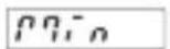
b. The following message is displayed
$$ \text { Prof } $$
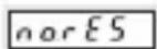
c. As soon as the keys are released, the following message is displayed
$$ \boxed {n o} $$
c1. To abort the programming cycle, keep the left key depressed and press the right key.
c2. Press the right key to switch to
$$ \text { YES } $$
d. To switch to the first parameter, keep the left key depressed and press the right key
e. As soon as the key is released, the display alternates every second between the menu title and the current menu item setting. If a key is pressed, only the menu item setting remains displayed.
f. Press the right key to change the menu item setting by one value every time. If numerical values are to be input (e.g. to set the factor), select the decade with the
left key and then set the value with the right key.
g. To switch to the next menu item, keep the left key depressed and press the right key
h. Selecting "Yes" in the last menu title "End-Pro" allows exiting the programming menu and taking over (saving) the new values. If "No" is selected, the programming routine restarts from the beginning; the last values set are maintained. They can now be modified once more or checked.
4. Programming routine
The settable parameters of the device are listed below, in the order in which they will be set. Thus, the device is entirely set after completion of the routine.
The top symbol always corresponds to the factory setting.
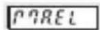
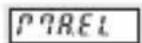
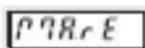
4.1 Input signal range (measuring range)
rRoGE
0.20mA 0...20mA
420n8 4...20 mA
0.10V 0...10V
2.10V 2...10V
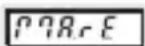
4.2. Measuring time
P7-t,
0.5 sec
0.1 sec
4.3 Decimal point setting
dP.Rct
The decimal point defines the number of displayed decimal places for the current measured value (only for display purposes).
0 00
0 no decimal place
0.0 one decimal place
0.00 two decimal places
0.000 three decimal places
00000
0.0000 four decimal places
4.4 Minimum input signal
lo
This menu item allows extending or reducing the measuring range.
If the input signal becomes lower than the value programmed here for the measuring range
4...20 mA, min. 3.5 mA, default 4 mA
0...20 mA, min. -0.5 mA, default 0 mA
2...10 V, min. 1.5 V, default 2 V
0...10 V, min. -0.5 V, default 0 V
Lo is displayed,
the display alternates between „Lo“ and the measured value.
Below the min. programmable measuring value, -1.9.9.9.9 is displayed to signal an underflow.
4.5 Display value for the lowest input signal
Lodis
+9999
A value to be displayed between -19999 and 99999 can be assigned to the lowest
99999
input signal (0V, 2V, 0mA, 4mA). The decimal point setting is taken into consideration (e.g. range 0...10V, this programmed value is issued for 0V).
4.6 Maximum input signal

This menu item allows extending or reducing the measuring range.
If the input signal exceeds the value programmed here for the measuring range
4...20 mA, max. 20.5 mA, default 20 mA
0...20 mA, max. 20.5 mA, default 20 mA
2...10 V, max. 10.5 V, default 10 V
0...10 V, max. 10.5 V, default 10 V
H_i^- is displayed,
the display alternates between „Hi“ and the measured value.
Above the max. programmable measuring range, 9.9.9.9.9 is displayed to signal an overflow. In case of an input voltage >10.8V there is an error, the message Error4 is displayed.
4.7 Display value for the highest input signal

The highest input signal (10V, 20mA) can be assigned a displayed value between -19999 and 99999. The decimal point setting is taken into consideration (e.g. range 0...10V, this programmed value is issued for 10V).
4.8 Minimum value display
Acquisition only within the measuring range set under 4.1, 4.4

Minimum value is displayed

The minimum value display is ignored and the next menu title is skipped
4.9 Minimum value reset

Manual reset (with red key) and electrical reset. When activated, the RESET input and the RESET key reset the minimum value to the current measured value.

No reset of the minimum value possible.

Electrical reset only. When activated, the RESET input resets the minimum value to the current measured value.
Manual reset only. When activated, the RESET key resets the minimum value to the current measured value.
4.10 Maximum value display

Acquisition only within the measuring range set under 4.1, 4.6

Maximum value is displayed

The maximum value display is ignored and the next menu title is skipped
4.11 Maximum value reset
Manual reset (with red key) and electrical reset. When activated, the RESET input and the RESET key reset the maximum value to the current measured value.
No reset of the maximum value possible.

Electrical reset only.
When activated, the RESET input resets the maximum value to the current measured value.
Manual reset only. When activated, the RESET key resets the maximum value to the current measured value.
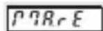
4.12 Total sum counter (totalizer)

The totalizer adds the current measured value every second. Totalizing only takes place within the set measuring range (4.1, 4.4, 4.6)

Measured value totalizing switched off

Measured value totalizing switched on In case of counter over or underflow (>99999 or <-19999), the display flashes every second. In case of values >99999, the counter goes on counting and looses no value until reaching the internal counter value 199999. When the internal counter value 199999 is reached, no more values are added. The display goes on flashing every second, but the value remains 99999. In the negative direction, when it reaches <-19999, the value stops immediately and flashes every second. No leading zero blanking in case of overflow.
4.13 Totalizer decimal point setting
As for the current measured value, the decimal point for the display can also be programmed for the sum (totalizer value). This has no effect on the display accuracy (only for display purposes). However, the expected maximum sum must be taken into consideration. If, as in example 8.5, the expected sum is 1000, one decimal place should be set at the maximum.
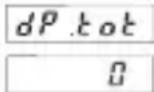
Factory setting

Sufficiently digits should be reserved for the display of the expected sum, as the sum stops at 199999 and the measuring result thus gets lost. If the 5-digit display is not sufficient, the "Factor" (4.14) and the "Scaler" (4.15) allow adjusting the sum accordingly.
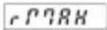
4.14 Factor
The displayed totalizer value can be adapted optimally for the measuring task thanks to the factor. If for example the current measured value must be displayed in small units such as grams, but the result of the sum must be displayed in kilograms or tons, input the corresponding factor (multiplier):

Select the decade with the left key and set a factor between 0.0001 and 9.9999 with the right key.
Note: Factor and scaling only affect the totalizer.
Total scaling = Factor x Scaling!
4.15 Scaling
Scaling allows extending the display range for the totalizer or reducing it for a very fine setting.
Select the required scale with the right key: 1 (factory setting), 0.1, 0.01, 0.001 or 0.0001. In example 8.6 on page 9 the tank can contain more than 100,000 l. Scaling 0.01 allows displaying the sum in hectoliters. As the scaler (= multiplier) only affects the sum, the current flow rate is still displayed in liters/second.
Note: Factor and scaling only affect the totalizer.
Total scaling = Factor x Scaling!
4.16 Totalizer reset
There are four possibilities to reset the totalizer. This setting affects the function of the Latch/Reset input.

Manual reset (with red key) and electrical reset. The MPI input operates as a RESET input. When actuated, it sets the totalizer to 0.
No reset possible.
The Latch/Reset input operates as a LATCH input. The current value displayed is frozen.

Electrical reset only. The reset key is disabled. The Latch/Reset input operates as a RESET input. When actuated, it sets the totalizer to 0.
Manual reset only. The Latch/Reset input operates as a LATCH input. The current value displayed is frozen.
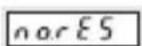
4.17 End of programming
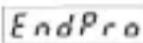

The programming routine is performed once more. The value set until now can be checked and modified.

The programming routine ends and all set values are taken over as new parameters. The device is then ready for operation.
5. Terminal assignment
-
10...30 V DC
-
GND
-
GND
-
Latch/Reset
-
0 (4)...20 mA DC
-
Analog GND
-
0 (2)...10 V DC
Measuring ranges: 0...10 VDC
2...10 VDC
0...20 mA DC
4...20 mA DC
Resolution: 14 bits
Accuracy: 0.1% ± 1 digit over the
whole measuring range at 20^ C
Null balancing: automatic
Temperature drift: < 70 ppm/K
Measuring time: 0.1 sec/0.5 sec
Current measurement:
max. 2.0 V DC
current limitation: 50 mA
Voltage measurement:
input resistance: > 1 MΩ
max. input voltage: 30 VDC
Voltage supply: 10...30 V DC, galvanically isolated
external fuse T 0.1 A
Current consumption: max. 50 mA
Ambient temperature: -20 °C...+65 °C
Storage temperature: -25 °C...+70 °C
Data backup: EEPROM
1 million storage cycles
or 10 years
Weight: approx. 50 g
Vibration resistance:
EN 60068-2-6
10...55 Hz/1 mm/30 min
Shock resistance: EN 60068-2-27
100 G: 2 ms
10 G: 6 ms
Protection level: IP65 (front side)
EMC: EN 55011 Class B,
EN 61000-6-2,
EN 61000-6-3,
EN 61326-1
UL-Certification File E128604
Error messages:
Err 0* Error/failure in the A/D section
Err 1** Invalid value (during programming)
Err 2** Lo-value > Hi-value
(during programming)
Err 3* Error/failure in FRAM
Err 4** Analog input signal exceeds the valid measuring range
Err 5* Error/failure in FRAM. Device null balancing not performed
* Please send device back for inspection
** Check input signal and programming
7. Scope of the delivery
- Digital display
- Mounting clip
- Front bezel for screw fastening cut-out 50x25 mm
- Front bezel for mounting clip fastening cut-out 50x25 mm
- Seal
voltage drop: 1 sheet of adhesive symbols
8. Examples
8.1 Temperature measurement
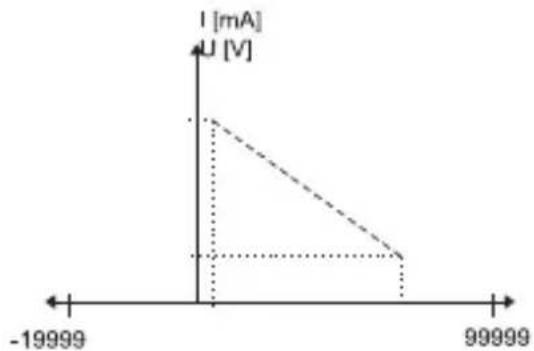
A temperature sensor with linear characteristics (in case of non-linear sensors, install linearizing components upstream) delivers 0 V at -10°C and 10 V at 80°C. The selected measuring range is 0...10 V. 0 V is the smallest measured value possible. The display value -10 is now assigned to this measured value. Accordingly, 10 V is the largest measured value. The display value 80 is assigned to this measured value. The display is now set for the sensor and can display any intermediate value.
line
| Time | U [V] | | -------- | ----- | | -19999 | -1 | | 99999 | 1 |Display value freely positionable within the measuring range
8.2 Filling level measurement
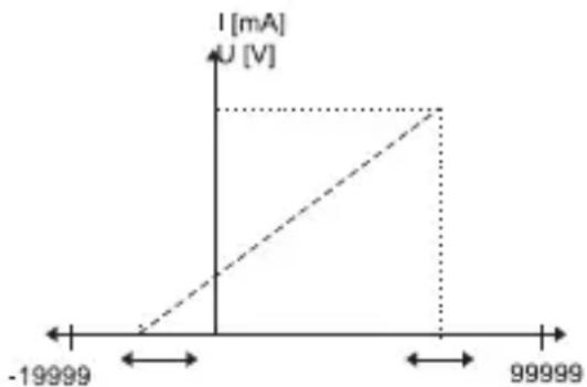
A filling level sensor with linear characteristics (in case of non-linear sensors, install linearizing components upstream) delivers 4 mA when a container is empty and 20 mA when it is full. The value 10 m ^3 must be displayed for the full container and 0 m ^3 for the empty container. The selected measuring range is 4...20 mA. 4 mA is the smallest measured value possible. The display value 0 can now be assigned to this measured value. Accordingly, 20 mA is the largest measured value. The display value 10 is assigned to this measured value. The display is now set for the sensor and can display any intermediate value.
8.3 Removed quantity
Instead of the filling quantity, the value to display is the removed quantity. The selected measuring range is again 4...20 mA. A display value of 10 is now assigned to the smallest measured value (4 mA) and a display value of 0 is assigned to the largest measured value (20 mA).
line
| X-axis | I [mA] | U [V] | |---|---|---| | -19999 | 0 | 0 | | 99999 | 0 | 0 |8.4 Filling level measurement with limit value display
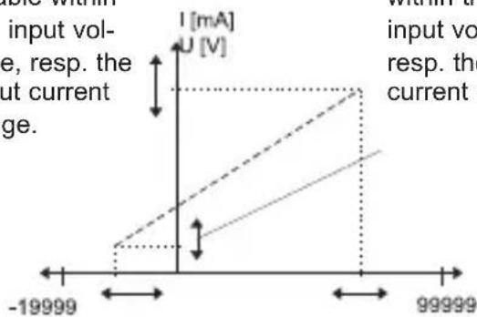
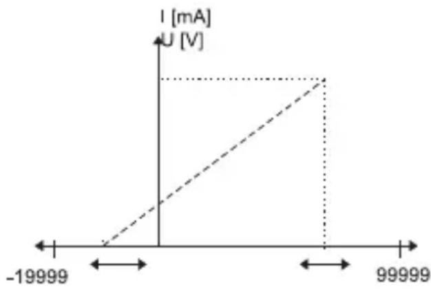
In this third case too, the available quantity must be displayed; the container has a capacity of 10 m^3 but it can be filled at the maximum to 8 m^3 . Moreover, the content shall not sink below 1 m^3 . So, for values > 8 m^3 , "Hi" must be displayed and, for values < 1 m^3 , "Lo" must be displayed.
The selected measuring range is 4...20 mA. The display value 0 is assigned to the smallest input value and 10 is assigned to the largest input value. In addition, the menu item "Minimum input signal" is used to set the measured value that corresponds to a content of 1 m³, e.g. 5.6 mA and the menu item "Maximum input signal" is used to set the measured value that corresponds to a content of 8 m³, e.g. 16.8 mA. Therefore, „Hi“ is displayed for input values > 16.8 mA and „Lo“ for input values < 5.6 mA.
Maximum input voltage or maximum input current freely positionable within the input voltage, resp. the input current range.
Minimum input voltage or minimum input current freely positionable within the input voltage, resp. the input current range.
line
| Time (s) | Current (mA) | Voltage (V) | | :--- | :--- | :--- | | -19999 | 0 | 0 | | 99999 | 0 | 0 | | 99999 | U [V] | U [V] | The chart displays a linear relationship between current and voltage over time. The input voltage is calculated as I = U [V], while the current change is calculated as U [V]. The output current change is calculated as I = U [V].Display value freely positionable within the display range
8.5 Weight measurement with totalizing
The quantity of granulate is to be determined by means of flow measurement. At full flow rate (= 10 kg/sec.), the measuring sensor delivers 20 mA
line
| X-axis | I [mA] | U [V] | |---|---|---| | -19999 | 0 | 0 | | 99999 | 0 | 0 |The selected measuring range is 0...20 mA. Assign the value 0 to the lowest input signal and 10 to the highest. To display the sum in tons, set a factor of 0.001.

The decimal point is only for display purposes. For a current value display of 10.0, the totalizer would add every time 100.
This must be taken into consideration accordingly when setting the factor.
If the current flow rate is to be displayed with one decimal place, set the factor to 0.0001.
8.6 Flow measurement with totalizing
The flowing quantity and the totalized quantity are to be displayed alternately. The measuring sensor with linear characteristics (in case of non-linear sensors, install linearizing components upstream) delivers 4 mA when stopped and 20 mA at full flow speed, which corresponds in this example to 90 l/minute.
Select with "range" the measuring area 4...20 mA and, for the minimum and maximum input signal "lo.act" and "hi.act", the respective factory setting.
Assign the display value 0 to the lowest input signal "lo.display" and assign the value 1.5 (corresponding to l/second) to the highest input signal "hi.display".
Set the decimal point for the totalizer "dp.tot" according to the expected maximum quantity: for the maximum volume of a 100,000 l bottling plant, select zero decimal place for the totalizer and, as this still is not sufficient, use "scaler" 0.01 to increase the display range by two places, in order to display the totalized quantity in hectoliters.
Press the right key to switch between the display of the current value and the display of the totalizer. Various factors allow displaying the totalized volume also in other units, e.g. with factor 2 in 0.5 l bottles or with factor 2.6420 in gallons.
Codix 534
Latch/Reset (borne 4)
Entrée courant (borne 5)
Analog GND (borne 6)
Entrée tension (borne7)
UL-Certification File E128604
Messages d'erreur :
line
| Time (ms) | Current (mA) | | --------- | ------------ | | -19999 | -1.0 | | 99999 | 0.0 |line
| Voltage | Current (mA) | |---|---| | -19999 | -1 | | 99999 | 1 |Latch/Reset (borne 4)
Entrada de corriente (borne 5)
Analog GND (borne 6)
text_image
48 [1.89] 24 [0.945]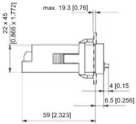
text_image
22 x 45 [0.866 x 1.772] max. 19.3 [0.76] 4 [0.15] 6.5 [0.256] 59 [2.323]Front panel cut-out:
text_image
53 [2.087] 28 [1.103]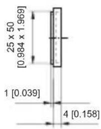
text_image
25 x 50 [0.984 x 1.969] 1 [0.039] 4 [0.158]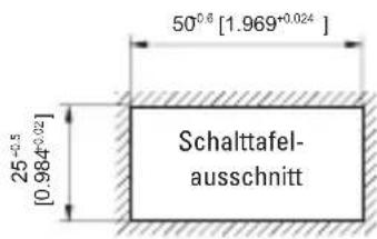
text_image
50°⁰.⁶ [1.969°⁰.⁰²⁴] 25⁺⁰·⁵ [0.984⁺⁰·⁰²] Schalttafel- ausschnitt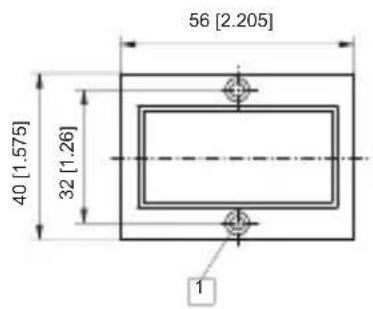
text_image
56 [2.205] 40 [1.575] 32 [1.26] 1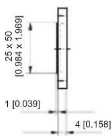
text_image
25 x 50 [0.984 x 1.969] 1 [0.039] 4 [0.158]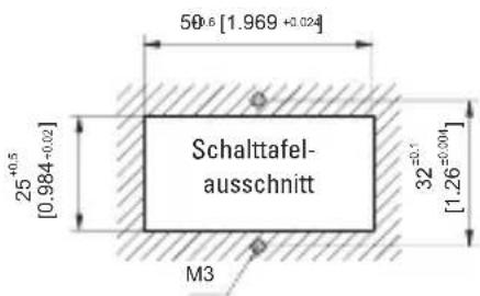
text_image
50±6 [1.969 +0.024] Schalttafel- ausschnitt 25+0,5 [0.984+0,02] M3 32=0,1 [1.26+0.004] [0,0]1 Senkung Af3, DIN 74 Countersinking Af3, DIN 74 Fraisure Af3, DIN 74 Svasatura Af3, DIN 74 Fresado Af3, DIN 74
Kübler Group
Fritz Kübler GmbH
Schubertstrasse 47
D-78054 Villingen-Schwenningen
Germany
Phone +49 7720 3903-0
Fax +49 7720 21564
info@kuebler.com
www.kuebler.com