KJ1350 - Pressure washer RIDGID - Free user manual and instructions
Find the device manual for free KJ1350 RIDGID in PDF.
| Product type | Water jet drain cleaner / Pressure washer |
| Brand | RIDGID |
| Model | KJ1350 |
| Motor | 1.5 HP, 1725 rpm, 14 A |
| Power supply | 115 V, 60 Hz, single-phase |
| Maximum pressure | 1350 psi (9.3 MPa) |
| Flow rate | 1.4 gpm (5.3 L/min) |
| Pump | Duplex plunger |
| Cleaning capacity | Ø 1¼" to 4" (32 to 100 mm), max length 200 ft (61 m) |
| Weight (drain cleaner only) | 30.5 kg (67 lb) |
| Dimensions (L × W × H) | Approximately 60 × 40 × 50 cm (estimated) |
| High pressure hose | Inner diameter 1/8" to 1/4" depending on use |
| Pulsation system | Yes, with additional pulsation valve (models -2) |
| Safety device | Ground fault circuit interrupter (GFCI) integrated into cord |
| Recommended extension cord | 12 AWG, 3-wire with ground, rated W or W-A |
| Included accessories | Nozzles H-21, H-22, H-24; 25 ft siphon hose; storage bag; cleaning rod |
| Mounting options | H-10 cart (optional) for transport and reel |
| Maximum water temperature | 60°C (140°F) |
| Warranty | Lifetime (defects in materials and workmanship) |
Frequently Asked Questions - KJ1350 RIDGID
User questions about KJ1350 RIDGID
0 question about this device. Answer the ones you know or ask your own.
Ask a new question about this device
Download the instructions for your Pressure washer in PDF format for free! Find your manual KJ1350 - RIDGID and take your electronic device back in hand. On this page are published all the documents necessary for the use of your device. KJ1350 by RIDGID.
USER MANUAL KJ1350 RIDGID
Read this Operator's Manual carefully before using this tool. Failure to understand and follow the contents of this manual may result in electrical shock, fire and/or serious personal injury.
Water Jetter Machines
natural_image
Industrial pressure regulator device (no visible text or symbols on body)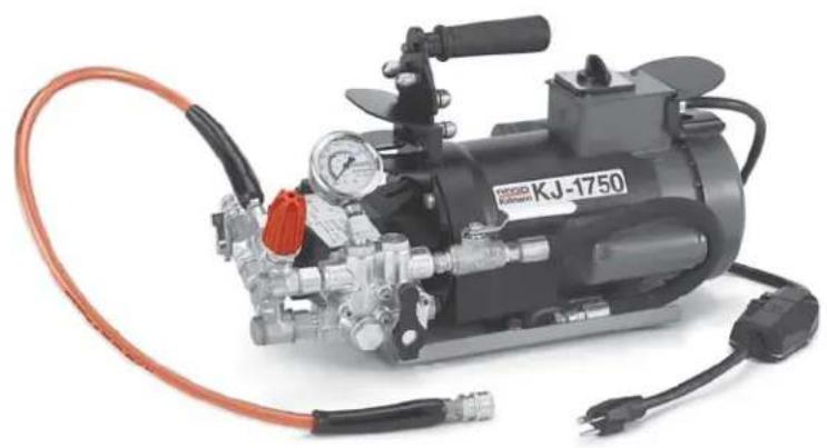
natural_image
Industrial pressure regulator device (KJ-1750) with hoses and control panel, no visible text or symbols on the device itself.RIDGID®
Table of Contents
Recording Form for Machine Model and Serial Number 1
General Safety Information
Work Area Safety....2
Electrical Safety 2
Personal Safety....2
Tool Use and Care....3
Service....3
Specific Safety Information
Jetter Safety....3
Description, Specifications and Standard Equipment
Description....4
Specifications....4
Standard Equipment 4
Jetter Nozzles and Hoses 4
Accessories....5
Machine Assembly
Instructions for Pump 5
Transport Carts....5
Machine Inspection....5
Machine and Work Area Set-Up
Jetter Nozzle Selection Chart ....7
Jetter Hose Selection Chart....7
Operating Instructions
Start-Up and Pressure Adjustment 8
Pulse Control Valves....9
Normal Jetting....9
Using the Pulse Mode to Negotiate Bends and Traps....9
Negotiating Difficult Bends....9
Encountering Blockages ....10
"Jet-Cleaning" or "Jetting" the Line 10
Pressure Wash Package ....10
Washer Operation....10
Accessories
Jetter Nozzles and Hoses....11
Jetter Accessories....11
H-5 Mini Hose Reel....11
Maintenance Instructions
Inlet Filter Screen....11
Jetter Nozzle Orifice....11
Jetter Flushing ......11
Winterizing 11
Machine Storage....12
Service and Repair....12
Troubleshooting....12
Wiring Diagrams....13
Lifetime Warranty ....Back Cover
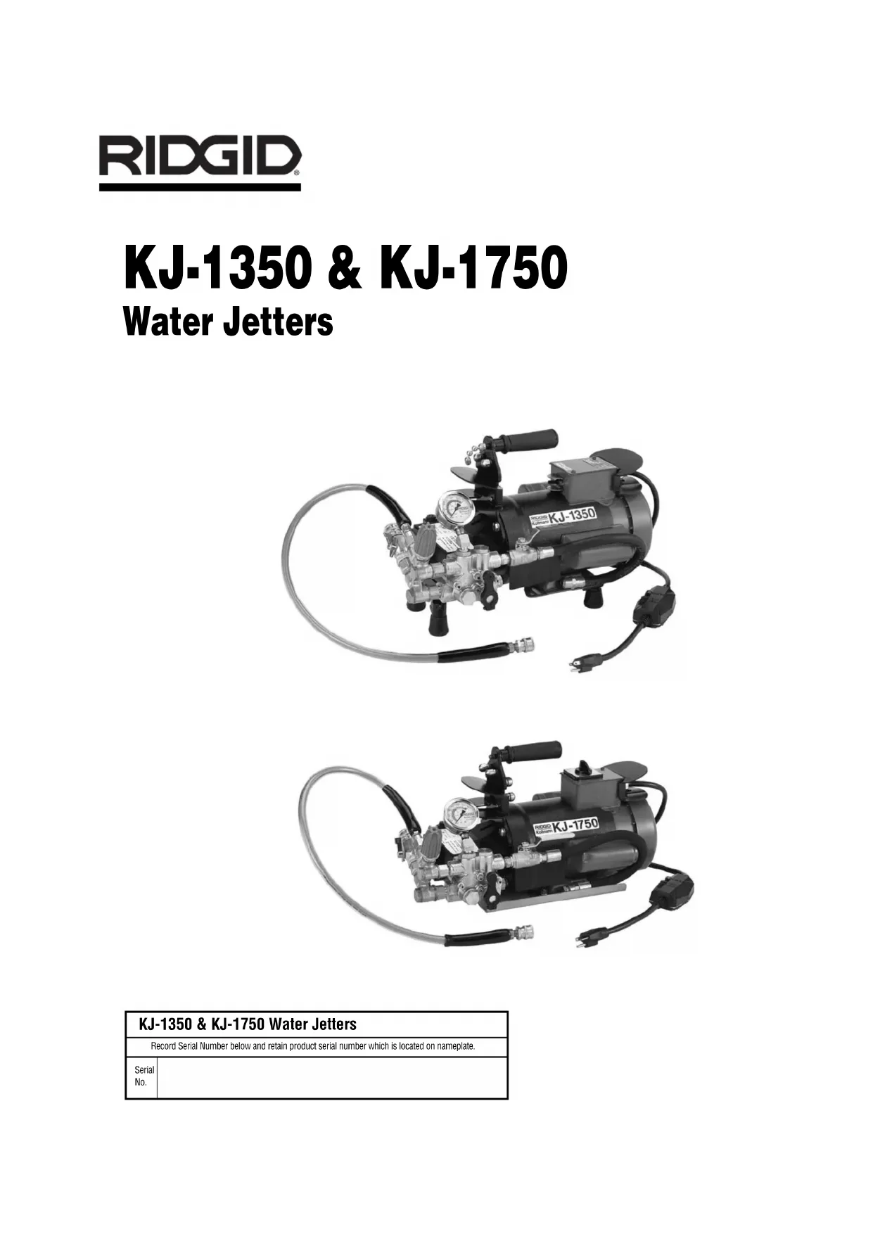
KJ-1350 & KJ-1750
Water Jetters
natural_image
Industrial pressure pump with attached hoses and control panel (no visible text or symbols)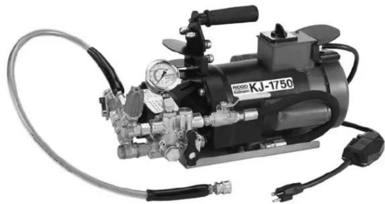
natural_image
Industrial pressure pump with attached hoses and control panel (no visible text or symbols)| KJ-1350 & KJ-1750 Water Jetters | |
| Record Serial Number below and retain product serial number which is located on nameplate. | |
| Serial No. | |
General Safety Information
WARNING! Read and understand all instructions. Failure to follow all instructions listed below may result in electric shock, fire and/or serious personal injury.
SAVE THESE INSTRUCTIONS!
Work Area Safety
- Keep your work area clean and well lit. Cluttered benches and dark areas invite accidents.
RISK OF FIRE!
- Do not operate tools in explosive atmospheres, such as in the presence of flammable liquids, gases or dust. Power tools create sparks which may ignite the dust or fumes.
- Keep by-standers, children, and visitors away while operating a power tool. Distractions can cause you to lose control.
Electrical Safety
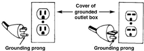
GROUNDING INSTRUCTIONS:
- Grounded tools must be plugged into an outlet, properly installed and grounded in accordance with all codes and ordinances. Never remove the grounding plug or modify the plug in any way. Do not use any adapter plugs. Check with a qualified electrician if you are in doubt as to whether the outlet is properly grounded. If the tool should electrically malfunction or break down, grounding provides a low resistance path to carry electricity away from the user.
text_image
Grounding prong Cover of grounded outlet box Grounding prong- Avoid body contact with grounded surfaces such as pipes, radiators, ranges and refrigerators. There is an increased risk of electrical shock if your body is grounded.
GROUND FAULT CIRCUIT INTERRUPTERS (GFCI):
- Water Jetter is provided with a ground-fault circuit-interrupter (GFCI) built into the power supply cord. This GFCI provides additional protection from the risk of electrical shock.
- Before using, test the Ground Fault Circuit Interrupter (GFCI) provided with the power cord to in-
sure the GFCI is operating properly. Damaged GFCI increases risk of electrical shock.
- Do not abuse cord or Ground Fault Circuit Interrupter (GFCI). Keep cord from heat, oil, and sharp edges. Damaged cords increase the risk of electrical shock.
EXTENSION CORDS:
- Use only an outdoor extension cord marked "W-A" or "W". These cords are rated for outdoor use and reduce the risk of electrical shock.
- Use only three-wire extension cords which have three-prong grounding plugs and three-pole receptacles which accept the machine's plug. Use of other extension cords will not ground the tool and increase the risk of electrical shock.
- Extension cords are not recommended unless they are plugged into a Ground Fault Circuit Interrupter (GFCI) found in circuit boxes or outlet receptacles. The GFCI on the machine power cord will not prevent electrical shock from the extension cords.
- Use proper extension cords. (See chart.) Insufficient conductor size will cause excessive voltage drop and loss of power.
| Minimum Wire Gauge for Extension Cord | |||
| Nameplate Amps | Total Length (in feet) | ||
| 0 – 25 26 | - 50 51 – 100 | ||
| 0 – 6 18 | AWG 16 AWG | 16 AWG | |
| 6 – 10 18 | AWG 16 AWG | 14 AWG | |
| 10 – 12 16 | AWG 16 AWG | 14 AWG | |
| 12 – 16 14 | AWG 12 AWG | NOT RECOMMENDED | |
- Do not abuse extension cords. Keep cord from heat, oil and sharp edges. Do not yank on any cord to disconnect. Damaged cord increases risk of electrical shock.
- Keep all electric connections dry and off the ground. Do not touch plugs or tool with wet hands. Reduces the risk of electrical shock.
- Always disconnect the extension cord from the receptacle before disconnecting the product from the extension cord. Reduces risk of electrical shock.
Personal Safety
- Stay alert, watch what you are doing and use common sense when operating a power tool. Do not use tool while tired or under the influence of drugs, alcohol, or medications. A moment of inattention while operating power tools may result in serious personal injury.
- Dress properly. Do not wear loose clothing or jewelry. Contain long hair. Keep your hair, clothing, and gloves away from moving parts. Loose clothes, jewelry, or long hair can be caught in moving parts.
- Avoid accidental starting. Be sure switch is OFF before plugging in. Carrying tools with your finger on the switch or plugging in tools that have the switch on invites accidents.
- Remove adjusting keys or wrenches before turning the tool ON. A wrench or a key that is left attached to a rotating part of the tool may result in personal injury.
- Do not overreach. Keep proper footing and balance at all times. Proper footing and balance enables better control of the tool in unexpected situations.
- Use safety equipment. Always wear eye protection. Dust mask, non-skid safety shoes, hard hat, or hearing protection must be used for appropriate conditions.
Tool Use and Care
- Do not force tool. Use the correct tool for your application. The correct tool will do the job better and safer at the rate for which it is designed.
- Do not use tool if switch does not turn it ON or OFF. Any tool that cannot be controlled with the switch is dangerous and must be repaired.
- Disconnect the plug from the power source before making any adjustments, changing accessories, or storing the tool. Such preventive safety measures reduce the risk of starting the tool accidentally.
- Store idle tools out of the reach of children and other untrained persons. Tools are dangerous in the hands of untrained users.
- Maintain tools with care. Keep valves, hoses, and nozzles in proper operating condition. Properly maintained tools are less likely to malfunction and cause injury.
- Check for misalignment or binding of moving parts, breakage of parts, and any other condition that may affect the tool's operation. If damaged, have the tool serviced before using. Many accidents are caused by poorly maintained tools.
- Use only accessories that are recommended by the manufacturer for your model. Accessories that may be suitable for one tool may become hazardous when used on another tool.
- Inspect tool and extension cords periodically and
replace if damaged. Damaged cords increase the risk of electrical shock.
- Keep handles dry and clean; free from oil and grease. Allows for better control of the tool.
- Should replacement of the cord become necessary, use only identical replacement parts that include GFCI protection. GFCI protection must be maintained to reduce the risk of electrical shock.
Service
- Tool service must be performed only by qualified repair personnel. Service or maintenance performed by unqualified repair personnel could result in injury.
- When servicing a tool, use only identical replacement parts. Follow instructions in the Maintenance Section of this manual. Use of unauthorized parts or failure to follow maintenance instructions may create a risk of electrical shock or injury.
Specific Safety Information
WARNING
Read this operator's manual carefully before using the RIDGID KJ-1350 or KJ-1750 Water Jetters. Failure to understand and follow the contents of this manual may result in electrical shock, fire and/or serious personal injury.
Call the Ridge Tool Company, Technical Service Department at (800) 519-3456 if you have any questions.
Jetter Safety
- Do not operate above rated pressure or 140^ (inlet water temperature). Tool will do a better and safer job if operated at recommended pressures and temperatures.
- Never permit the end of hose to rotate out of the pipe being cleaned. Hose can whip and nozzle spray can penetrate skin causing serious injury.
- Use rubber gloves and rubber boots. Insulate against possible electrical shock if tools should electrically malfunction or break down.
- Water spray should not be pointed at any human. High pressure spray can result in serious injury. If fluid seems to have penetrated sin, seek emergency medical attention at once.
-
Be careful when cleaning drains where cleaning compounds have been used. Avoid direct contact with skin and eyes. Serious burns can result from some drain cleaning components.
-
Jetter is designed to clean drains. Follow instructions in Operator's Manual on machine's uses. Other uses may increase the risk of injury.
- Do not spray flammable liquids. Spraying flammable liquids could cause a fire or explosion.
- Do not spray toxic chemicals such as insecticide or weed killer. Chemicals can be harmful to personnel.
- Never clean the machine using its own spray wand. High pressure spray may damage machine components.
- Do not spray electrical apparatus or wiring. Reduces the risk of electrical shock.
Description, Specifications and Standard Equipment
Description
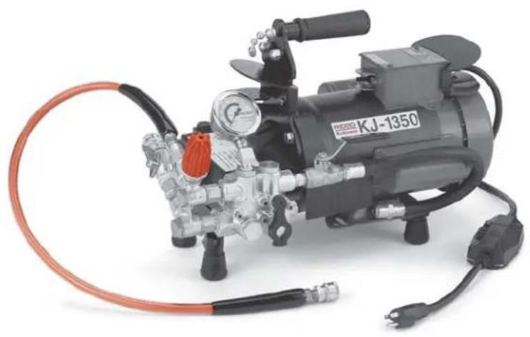
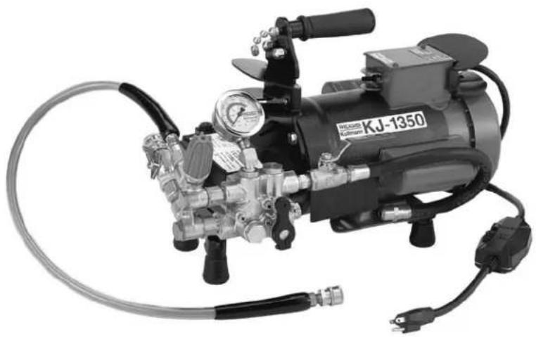
The RIDGID ^® KJ-1350 and KJ-1750 are portable jetters designed to use the combination of water pressure and flow to clear grease and soft blockages out of 1 ^1/4 " to 4" drain lines. The Jetters can be either hand carried or combined with a two wheeled cart and hose reel for transporting.
The KJ-1350 has a 112 HP electrical motor with a 1350 PSI pressure rating and a 1.4 GPM flow rate. It is designed for residential and light commercial applications.
The KJ-1750 has 2 HP motor with a 1750 PSI pressure rating and a 1.4 GPM flow rate. It is designed for heavy commercial and industrial applications.
Specifications
KJ-1350
Line Capacity......Recommended for 1 ^1/4 to 4" drain lines through 200 feet.
Motor .... ^1^1/_2 HP @ 1725 RPM 14 amps
Pump ......Duplex Plunger
Pressure....1350 PSI
Flow Rate 1.4 GPM
Weight (jetter only)...67 lbs. (30,5 kgs)
KJ-1750
Line Capacity......Recommended for 1 ^1/4 " to 4" drain lines through 200 feet.
Motor ......2 Hp @ 1725 RPM 17 amps
Pump ......Duplex Plunger
Pressure....1750 PSI
Flow Rate 1.4 GPM
Weight (jetter only)...75 lbs. (34,0 kgs)
Standard Equipment Machine Options (115V)
| Catalog No. | Model No. | Description |
| 62587 | KJ-1350 KJ | - H-21, H-22, and H-24 18 " NPT Nozzles- 25' x 18 " Sink Trap Hose- Nylon Storage Bag- Nozzle Cleaning Tool |
| 62597 KJ | -1350-C | Above With:- H-10 Cart- 100' x 18 " Trap Hose |
| 63107 | KJ-1350-2 KJ | - H-21, H-22, and H-24 18 " NPT Nozzles- 50' x 18 " Sink Trap Hose- Nylon Storage Bag- Nozzle Cleaning Tool |
| 63112 KJ | -1350-2C | Above With:- H-10 Cart- 100' x 18 " Trap Hose |
| 62687 | KJ-1750 KJ | - H-41, H-42, and H-44 18 " NPT Nozzles- H-51 and H-52 14 " NPT Nozzles- 50' x 18 " Sink Trap Hose- Nylon Storage Bag- Nozzle Cleaning Tool |
| 62697 KJ | -1750-C | Above With:- H-30 Cart- 110' x 12 " Jet Hose |
| 67332 | KJ-1750-SC | 62687 with:- H-10 Cart- 100' x 14 " Trap Hose |
Machine Options (230V)
| Catalog No. | Model Description | |
| 66447 | KJ-1750-E KJ-1750 230V Jetter with Dual Pulse– H-41, H-42, and H-44 18 " NPT Nozzles– 50' x 18 " Sink Trap Hose– Nylon Storage Bag– Nozzle Cleaning Tool | |
| 66442 | KJ-1750-E SC | Above With: H-10 Cart, 100' x 14 " Trap Hose |
Jetter Nozzles and Hoses
| Catalog No. | Model Description | Hose Hose I.D. O.D. | |||
| 64707 | H-21 KJ-1 | 350 Propulsion Nozzle | 18'' NPT | — | — |
| 64712 | H-22 KJ-1 | 350 Penetrating Nozzle Fits | 18'' & | ||
| 64717 | H-24 KJ-1 | 350 Drop Head Nozzle | 14'' Hose | ||
| 82832 | H-25 KJ-1 | 350 Spin Nozzle | 18'' NPT | ||
| 64722 | H-31 KJ-1 | 350 Propulsion Nozzle | 14'' NPT — — | ||
| 64727 | H-32 KJ-1 | 350 Penetrating Nozzle Fits | 12'' Hose | ||
| 64742 | H-41 KJ-1 | 750 Propulsion Nozzle | 18'' NPT | — | — |
| 64747 | H-42 KJ-1 | 750 Penetrating Nozzle Fits | 18'' & | ||
| 64752 | H-44 KJ-1 | 750 Drop Head Nozzle | 14'' Hose | ||
| 82837 | H-45 KJ-1 | 750 Spin Nozzle | 18'' NPT | ||
| 64757 | H-51 KJ-1 | 750 Propulsion Nozzle | 14'' NPT — — | ||
| 64762 | H-52 KJ-1 | 750 Penetrating Nozzle Fits | 12'' Hose | ||
| 52957 | H-1825 | 18'' × 25' Sink Trap Hose | 18'' | 38'' | |
| 53037 | H-1850 | 18'' × 50' Sink Trap Hose | 18'' | 38'' | |
| 45792 | H-1425 | 14'' × 25' | 18'' | 14'' | |
| 47597 | H-1435 | 14'' × 35' | 18'' | 14'' | |
| 47602 | H-1450 | 14'' × 50' | 14'' Trap Hose | 18'' | 14'' |
| 49272 | H-1475 | 14'' × 75' | 18'' | 14'' | |
| 49277 | H-1400 | 14'' × 100' | 18'' | 14'' | |
| 64732 | H-1415 | 14'' × 150' | 18'' | 14'' | |
| 50002 | HL-1 Flexible Leader, | 12'' × 12'' | 18'' | 38'' | |
| 50007 | HL-2 Flexible Leader, | 12'' × 18'' | 18'' | 38'' | |
| 47607 | H-1250 | 12'' × 50' | 14'' | 14'' | |
| 47612 | H-1275 | 12'' × 75' | 14'' | 14'' | |
| 47617 | H-1200 | 12'' × 100' | 14'' | 14'' | |
| 51587 | H-1211 | 12'' × 110' | 12'' Jet Hose | 14'' | 12'' |
| 49487 | H-1215 | 12'' × 150' | 14'' | 14'' | |
^1/5 NPT fits ^1/4 Trap Hose; ^1/4 NPT fits ^1/2 and ^3/_8 Jet Hose
Jetter Accessories
| Catalog ModelNo. No. Description | ||
| 64697 H-10 H-10 Cart with Hose Reel | ||
| 62592 | H-10 WH | H-10 Cart with Hose Reel and 100' x 1/2" Trap Hose |
| 62882 H-5 Mini Hose Reel (fits H-10 cart) 150' x 1/2" Capacity | ||
| 64737 H-30 H-30 Cart with Hose Reel | ||
| 62877 | H-30 WH | H-30 Cart with Hose Reel and 110' x 1/2" Jet Hose |
| 62887 HP-EL Pressure Wash Package, Electric Jetters | ||
| 64702 HW-EL Wash Wand, Electric Jetters | ||
| 51572 H-1235 | 1/2" x 35' Wash Hose | |
| 62897 H-10A KJ-1750 Adapter to Fit H-10 Cart | ||
| 62892 H-30A KJ-1350 Adapter to Fit H-30 Cart | ||
| 48367 H-25 Winterizing Kit | ||
| 47542 H-21 Nozzle Cleaning Tool | ||
| 67187 H-32 Jet Vac | ||
Machine Assembly
WARNING
To prevent serious injury, proper assembly of the KJ-1350 and KJ-1750 Jetters is required. The following procedures should be followed:
Instructions for Pump
Remove plug in pump and replace with dipstick/breather cap. Check the pump oil level (jetter is shipped with oil). If oil is low, fill with SAE 30W non-detergent oil.
Transport Carts
H-10 Cart
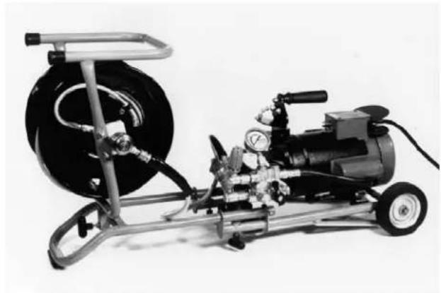
The two-wheeled cart has been designed to accept the KJ-1350 and the KJ-1350-2 without the need of tools. Lift and slide the jetter onto the cart making sure the one end engages the cart and on the other end, the post inserts into the receptacle (Figure 1). Tighten the T-handle to lock the jetter down. An adapter kit is available to mount the KJ-1750 on the H-10.
The hose reel and 100 feet of 14'' ID jetter hose mounts to the receptacle closest to the handle (Figure 1). Place the post on the reel into the socket and tighten the T-handle.
The length of the H-10 transport cart can be shortened for storage or lengthened by loosening two T-handles on the rails and sliding the handle in or out.
natural_image
Mechanical pressure pump assembly with motor, hoses, and cylindrical component (no visible text or symbols)Figure 1 – H-10 Cart and Hose Reel
⚠ WARNING Make sure all T-handles are fully tightened prior to transporting or lifting.
H-30 Cart and Hose Reel
The larger H-30 Cart and Hose Reel is designed to accept the KJ-1750 without the need of tools. Lift the jetter onto the deck and place over the locator pins. Hold in place and attach front and back clips to jetter base. An adapter kit is available to mount the KJ-1350's to the H-30.
Machine Inspection
WARNING

To prevent serious injury, inspect your Jetter. The following inspection procedures should be performed on a daily basis.
- Check pump oil level. If low, fill with a SAE 30 weight non-detergent oil.
NOTE! Jetter unit should be stored base down. Never store in up-right position as oil from pump will leak from reservoir.
-
Inspect the Jetter for any broken, missing, misaligned or binding parts as well as any other conditions which may affect the safe and normal operation of the machine. If any of these conditions are present, do not use the Jetter until any problem has been repaired.
-
Inspect the power cord, ground fault circuit interrupter (GFCI) and plug for damage. If the plug has been modified, is missing the grounding pin or if the
cord is damaged, do not use the jetter until the cord has been replaced.
⚠ WARNING When replacing cord, use only identical replacement parts that includes GFCI protection.
- Check inlet filter screen for debris that can restrict water flow into the pump resulting in poor performance. If filter screen is dirty or clogged, remove, clean and replace.
- Use accessories that are designed for your Jetter and meet the needs of your application. The correct accessories allow you to do the job successfully and safely. Accessories suitable for use with other equipment may be hazardous when used with this machine.
- Clean any oil, grease or dirt from all equipment handles and controls. This reduces the risk of injury due to a tool or control slipping from your grip.
- Check the jetter nozzle orifices for debris. If an orifice is blocked, use nozzle cleaning tool to clear and remove debris.
- Inspect hoses for wear and damage. Hoses should be replaced when they become damaged.
⚠ WARNING Damaged hoses can burst causing serious injury. Only use hoses whose pressure rating meets or exceeds that of the jetter.
Machine and Work Area Set-Up
WARNING

natural_image
Silhouette of a person running with a flag, no text or symbols present
natural_image
Abstract black jagged spike pattern on white background (no text or symbols)To prevent serious injury, proper set-up of the machine and work area is required. The following procedures should be followed to set-up the machine:
-
Check work area for:
-
Adequate lighting.
- No flammable liquids, vapors or dust that may ignite.
• 20 amp grounded electrical outlet. - Clear path to the electrical outlet that does not contain any sources of heat or oil, sharp edges or moving parts that may damage electrical cord.
- Dry place for machine and operator. Do not use the machine while standing in water.
- Water supply.
NOTE! If a connection is made to a potable water system, the system should be protected against backflow in accordance with all local codes and ordinances.
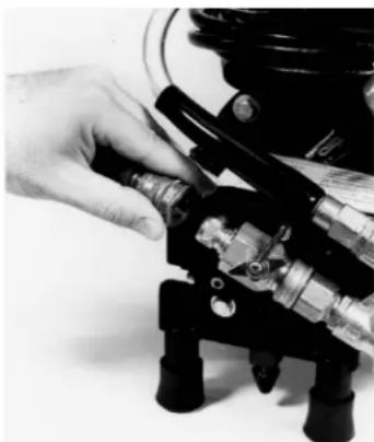
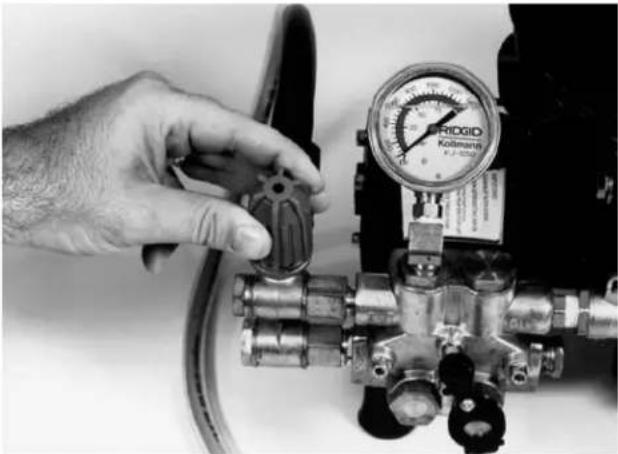
- Connect the quick coupling fitting to the water supply hose. Connect water supply hose to the jetter inlet and close the inlet supply valve. (Figure 2)
natural_image
Close-up of a hand operating a mechanical valve assembly (no visible text or symbols)Figure 2 – Connect Water Supply Hose to Jetter. Close Inlet Supply Valve (shown in closed position.)
- Connect the other end of the water supply hose to the water faucet and turn the faucet on. Make sure there are no kinks or unnecessary bends in the supply hose.
CAUTION Hot water improves the jetter's performance, particularly when clearing grease blockages. Limit water temperature to below 140°F.
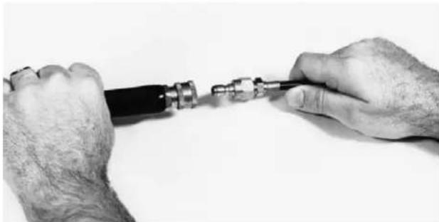
- Connect a jetter hose to the jetter's outlet quick coupling on the end of the connection hose (Figure 3). (Refer to Jetter Hose Selection Chart)
- If a hose reel is used, attach connection hose to plug fitting on hose reel.
-
Insert jetter hose 6" - 8" into drain without a jetter nozzle.
-
Open the inlet supply valve and run water through the jetter and hoses with unit OFF.
-
Continue to run water through the jetter until all air has been purged.
-
Close the inlet supply valve.
NOTE! Both the KJ-1350's and KJ-1750 Jetters have check valves for back flow prevention.
- Attach a jetter nozzle to the jet hose. (Refer to Jetter Nozzle Selection Chart.) Hand-tighten for a snug fit. Over-tightening can interfere with water flow through the nozzle orifices causing reduced flow and poor performance.
natural_image
Close-up of hands holding a small mechanical connector or tool, no visible text or symbolsFigure 3 – Connect jetter hose to jetter
⚠ WARNING Nozzles should not be removed from the drain while pressurized. Mark the hose at a distance of 24" (60cm) from nozzle to indicate the location of the nozzle.
- Insert the jet hose into the line several feet.
- Open the inlet supply valve and verify that water flows freely through the nozzle.
- Plug the Jetter into the electrical outlet making sure to position the power cord along the clear path selected earlier. If the power cord does not reach the outlet, use an extension cord in good condition.
⚠ WARNING To avoid electrical shock and electrical fires, never use an extension cord that is damaged or does not meet the following requirements:
- The cord has a three-prong plug similar to shown in Electrical Safety section.
- The cord is rated as "W" or "W-A" if being used outdoors.
- The cord has sufficient wire thickness (12 AWG). If the wire thickness is too small, the cord may overheat, melting the cord's insulation or causing nearby objects to ignite.
⚠ WARNING To reduce risk of electrical shock, keep all electrical connections dry and off the ground. Do not touch plug with wet hands. Test the Ground Fault Circuit Interrupter (GFCI) provided with the electric cord to insure it is operating correctly. When test button is pushed in, the indicator light should go off. Reactivate by pushing the reset button in. If indicator light goes on, the machine is ready to use. If the GFCI does not function correctly, do not use the machine.
JETTER NOZZLE SELECTION CHART
| KJ-1350 KJ-1750 | |||
| Thread Size | ^1/_8 NPT | ^1/_8 NPT | ^1/_4 NPT |
| Hose Inside Diameter | ^1/_8 & ^3/_16 | ^1/_8 & ^3/_16 | ^1/_4 |
| Features three reverse jet thrusts for maximum propulsion to jet long distances. Use this nozzle for most applications. | H-21 H-41 H-51 | ||
| Uses three jet thrusters in reverse plus one jet pointed forward to penetrate solid grease or sludge blockages. The forward jet blasts a small hole in the blockage for the nozzle to follow. It is also very effective when jetting ice blockages. | H-22 H-42 H-52 | ||
| Use the drop head to help negotiate difficult bends. | H-24 H-44 | ||
| Use spinner nozzle to clean grease and similar blockages. | H-25 H-45 | ||
JETTER HOSE SELECTION CHART
| Applications Pipe Size Size Size ID | Nozzle Hose | Hose | ||
| Bathroom sinks, urinals,and small lines. 1 | ^1/_4'' - 2'' | ^1/_5'' NPT | ^1/_8'' | ^1/_8'' |
| Kitchen sinks, laundry tubs and stacks,clean-outs, and vents. | 2'' - 3'' | ^1/_8'' NPT | ^1/_4'' | ^3/_16'' |
| Shower and floor drains, lateral lines,and grease traps. | 3'' - 4'' | ^1/_4'' NPT | ^1/_2'' | ^1/_4'' |
Operating Instructions
WARNING
natural_image
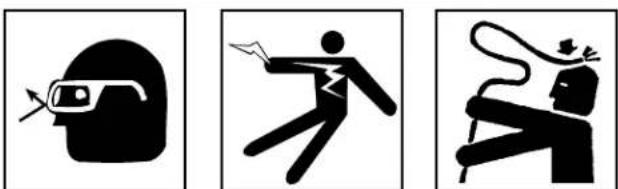
Three black-and-white pictograms showing a helmet, a person running with a tool, and a person running with a rope (no text or symbols)Always wear eye protection to protect eyes from dirt and other foreign objects. Use rubber gloves and rubber boots.
Do not spray flammable liquids or toxic chemicals.
Water spray should not be pointed at any human. Do not hold nozzle when pressurized.
Start-Up and Pressure Adjustment
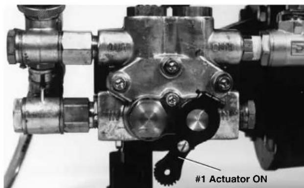
NOTE! Both the KJ-1350 and KJ-1750 Jetters have pulse actuators (Figure 5). The KJ-1350-2 and KJ-1750 have an additional pulse valve (Figure 7). Both the pulse actuator and pulse dampener valve must be in the OFF position prior to turning the jetter switch ON. To obtain maximum pressure, both pulse controls must be OFF.
-
Turn the unloader valve counter-clockwise to insure the pressure is backed down. Turn jetter switch ON and adjust the unloading valve so that the pressure gauge shows a maximum of 1350 PSI (green zone) on the KJ-1350 and KJ-1350-2. At this pressure, the KJ-1350 Jetters draw approximately 14 amps when supplied with 115 volt A/C current.
-
On the KJ-1750, adjust the unloading valve so that the pressure gauge shows 1750 PSI (green zone). At this pressure, the KJ-1750 draws approximately 17 amps when supplied with 115 volt A/C current. (Figure 4)
NOTE! Operating pressure is increased by rotating the unloading valve clock-wise +. If electrical circuit is not dedicated to Jetter, it may be necessary to reduce pressure (amp draw) to prevent tripping the circuit breaker or blowing a fuse.
natural_image
Close-up of a hand adjusting a pipe valve with a digital pressure gauge (no visible text or symbols)Figure 4 – Adjust the unloading valve
- If the jetter will not generate pressure:
- Make sure the water faucet is completely OPEN and the inlet supply valve is OPEN.
- Check the filter screen at the inlet port to the jetter. Make certain it is clear of debris.
- Cycle the pulse actuator on the KJ-1350 and KJ-1750 ON and OFF several times while the jetter is running to clear any trapped air in the system.
- Cycle the pulse dampener valve on the KJ-1350-2 and KJ-1750 ON and OFF several times to clear trapped air.
- Rotate unloader valve clockwise to make sure it increases pressure.
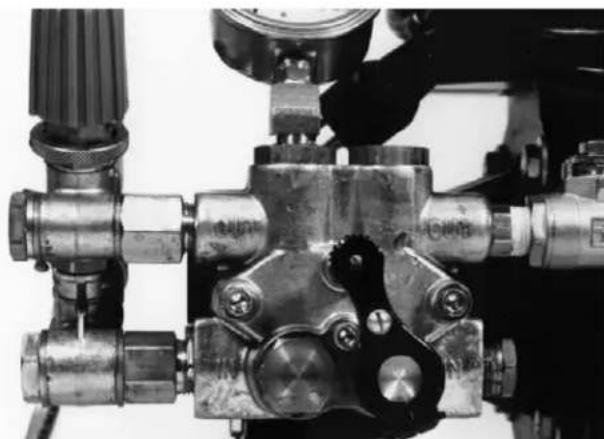
natural_image
Close-up of a mechanical valve assembly with no visible text or symbolsFigure 5 – Pulse Actuator ON
natural_image
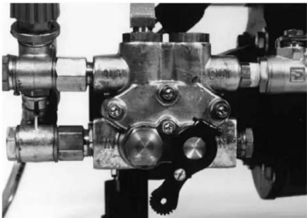
Close-up of a mechanical valve assembly with no visible text or symbolsFigure 6 – Pulse Actuator OFF
Pulse Control Valves
The KJ-1350 and KJ-1750 Jetters have a pulse actuator on the pump. Rotating the lever clockwise will engage the pulse. The KJ-1350-2 and KJ-1750 Jetters have two levels of pulsation with the addition of a pulse valve. There are now three different pulses:
| Actuator (#1) Valve (#2) | |||
| Normal | OFF | All | OFF |
| Bends & Traps OFF ON KJ-1750 | |||
| Difficult Bends ON ON | |||
For optimum jetter performance, you must understand the proper use of the pulse actuator and pulse valve.
Normal Jetting
Turn pulse actuator (#1) to the OFF position. Turn the pulse valve (#2) on the KJ-1350-2 and KJ-1750 to the OFF position. This results in maximum pressure but no pulse action.
-
When the jetter nozzle encounters a bend, its advance will usually slow or stop. The jetter hose has a slight bend or set to it. The reverse thrust of the nozzle will advance the jetter hose but it is also necessary to manually feed and rotate the jetter hose to work the set around the bends.
-
If the hose won't advance, pull back on the hose slightly and rotate the hose a quarter to a half turn. Then advance the hose forward.
-
If the jetter hose is not advancing, it may be necessary to induce some pulse action.
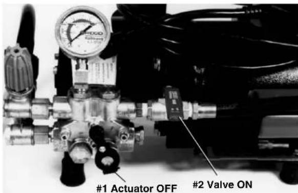
text_image
#1 Actuator OFF #2 Valve ONFigure 7 – Negotiating Bends and Traps
Using the Pulse Mode to Negotiate Bends and Traps
In some cases, simply rotating the hose will not be enough to negotiate a bend or trap. In these instances, turn the pulse actuator (#1) to the OFF position and valve (#2) for KJ-1350-2 and KJ-1750 to the ON position (Figure 7). In the pulse mode, the pump induces large pulsation and jet-ter hose vibration. Rotating the hose while operating in the pulse mode will normally overcome stubborn bends and traps.
KJ-1350-2 Negotiating Difficult Bends w/ KJ-1350-2 and KJ-1750
By turning the pulse actuator (#1) and the pulse valve (#2) to the ON position on the KJ-1350-2 and the KJ-1750 will achieve a higher amplitude of pulse. This will allow the jetter hose and nozzle to vibrate and negotiate difficult bends. (Figure 8)
text_image
#1 Actuator ONFigure 8 – Negotiating Difficult Bends
NOTE! In the pulse mode, the jetter's pressure gauge will read approximately 400 - 600 PSI.
NOTE! If at any time during the jetting process the pressure oscillates up and down between 100 and 1000 PSI, stop the jetter: Turn the Jetter and water supply OFF, remove the jetter nozzle and check the nozzle orifices (They are probably blocked). Clean them with the nozzle cleaning tool by pushing the proper size wire completely through each thruster orifice.
If the problem persists, remove the nozzle and insert the hose into the drain. Check the inlet filter screen at the inlet port and make sure it is clean. Restart to flush the system of any trapped air or debris that could be hampering the unit's operation.
Once through the bend or trap, return the pulse control actuator lever and valve to the OFF position. Continue the jetter head's advance.
Encountering Blockages
Normally, the jetter nozzle will pass right through grease or soft blockages. More stubborn blockages may require manual manipulation of the hose combined with the pulse action of the pump.
Once through the obstruction, pass the jetter nozzle back and forth several times through that section of the drain to ensure it is thoroughly cleared, then advance the nozzle several feet further down the line before retrieving the hose.
"Jet-Cleaning" or "Jetting" the Line
The Jetter's cleaning action occurs by the nozzle orifices directing high pressure water at the walls of the drain line. This same pressure produces the thrust that pushes the nozzle down the line. This cleaning action helps to restore the drain to the full inside line diameter. The slower the jetter hose is retrieved, the better the results.
Before the jetter hose is retrieved back out of the drain, turn the pulse dampener valve (#2) to the OFF position. This will maximize the pressure and flow at the nozzle. Slowly retrieve the jetter hose and clean the inside walls of the drain.
⚠ WARNING Never permit end of hose to rotate out of the pipe being cleaned. Hose can whip and nozzle spray can penetrate skin causing serious injury.
Pressure Wash Package
Both the KJ-1350 and KJ-1750 can operate as pressure washers to spray wash service vehicles, tools, drain cleaning equipment and cables. The wash wand mounted to the 14 " x 35' hose is attached to the jetter outlet port. Detergent can be dispensed for more effective cleaning by using the injector manifold. Attach the supply hose to the manifold and submerse the other end into a liquid solution.
Washer Operation
⚠ WARNING Water spray should not be pointed at any human.
To utilize the pressure wash feature make sure both pulse valves are in the OFF position. Adjust system pressure with the wash wand activated. The wash wand will fit the 14 " ID x 35' hose provided or any 14 " ID jetter hose. The injector introduces a detergent into the water flow for more effective cleaning. To use the injector:
- Attach the injector to the outlet port by removing the connection hose and quick coupling on the Jetter. Use thread sealant to prevent any leaks. Make sure arrow on manifold is going in the right direction (away from .letter).
- Re-attach connection hose and attach wash wand hose to quick coupling.
- Place one end of a siphon hose into the detergent's container and other end on injector manifold.
- The wash wand has two adjustments on the nozzle. By rotating the nozzle the wash pattern can be wide or narrow. The nozzle can be pushed forward for low pressure. Detergents are only dispensed when wash wand nozzle is in the low pressure setting.
- After the application, pull the nozzle back to achieve full pressure.
⚠ WARNING Do not spray flammable liquids or toxic materials.
Accessories
⚠ WARNING Only the following RIDGID products have been designed to function with the Water Jetting Machine. Other accessories suitable for use with other tools may become hazardous when used on the machines. To prevent serious injury, use only the recommended accessories.
Jetter Nozzles and Hoses
| Catalog No. | Model Description I.D. O.D. | ||||
| 64707 | H-21 KJ-1350 Propulsion Nozzle | 18'' NPT | |||
| 64712 | H-22 KJ-1350 Penetrating Nozzle | Fits 18'' & | — | — | |
| 64717 | H-24 KJ-1350 Drop Head Nozzle | 14'' Hose | |||
| 82832 | H-25 KJ-1350 Spin Nozzle | 18'' NPT | |||
| 64722 | H-31 KJ-1350 Propulsion Nozzle | 14'' NPT | — — | ||
| 64727 | H-32 KJ-1350 Penetrating Nozzle | Fits 12'' Hose | |||
| 64742 | H-41 KJ-1750 Propulsion Nozzle | 18'' NPT | |||
| 64747 | H-42 KJ-1750 Penetrating Nozzle | Fits 18'' & | — | — | |
| 64752 | H-44 KJ-1750 Drop Head Nozzle | 14'' Hose | |||
| 82837 | H-45 KJ-1750 Spin Nozzle | 18'' NPT | |||
| 64757 | H-51 KJ-1750 Propulsion Nozzle | 14'' NPT | — — | ||
| 64762 | H-52 KJ-1750 Penetrating Nozzle | Fits 12'' Hose | |||
| 52957 | H-1825 18'' × 25' Sink Trap Hose | 18'' 18'' 18'' | 318'' 315'' | ||
| 53037 | H-1850 18'' × 50' Sink Trap Hose | ||||
| 45792 | H-1425 14'' × 25' | 115'' 115'' 115'' | 14'' 14'' 14'' | ||
| 47597 | H-1435 14'' × 35' | ||||
| 47602 | H-1450 14'' × 50' | 115'' Trap Hose | 115'' 115'' 115'' | ||
| 49272 | H-1475 14'' × 75' | ||||
| 49277 | H-1400 14'' × 100' | ||||
| 64732 | H-1415 14'' × 150' | ||||
| 50002 | HL-1 Flexible Leader, 14'' × 12'' | 18'' 18'' | 315'' 315'' | ||
| 50007 | HL-2 Flexible Leader, 12'' × 18'' | ||||
| 47607 | H-1250 18'' × 50' | 14'' 14'' 14'' | 12'' 12'' | ||
| 47612 | H-1275 18'' × 75' | ||||
| 47617 | H-1200 18'' × 100' | ||||
| 51587 | H-1211 18'' × 110' | 12'' Jet Hose | 14'' 14'' | 12'' 12'' | |
| 49487 | H-1215 18'' × 150' | ||||
| 51597 | H-1220 18'' × 200' | ||||
18 NPT fits 14 Trap Hose
12 NPT fits 12 and 38 Jet Hose
Jetter Accessories
| Catalog No. | Model Description | |
| 64697 | H-10 H-10 Cart with Hose Reel | |
| 62592 | H-10 WH | H-10 Cart with Hose Reel and 100' x 12 " Trap Hose |
| 62882 | H-5 Mini Hose Reel (fits H-10 cart) 150' x 14 " Capacity | |
| 64737 | H-30 H-30 Cart with Hose Reel | |
| 62877 | H-30 WH | H-30 Cart with Hose Reel and 110' x 12 " Jet Hose |
| 62887 | HP-EL Pressure Wash Package, Electric Jetters | |
| 64702 | HW-EL Wash Wand, Electric Jetters | |
| 51572 | H-1235 | 12 " x 35' Wash Hose |
| 62897 | H-10A KJ-1750 Adapter to Fit H-10 Cart | |
| 62892 | H-30A KJ-1350 Adapter to Fit H-30 Cart | |
| 48367 | H-25 Winterizing Kit | |
| 47542 | H-21 Nozzle Cleaning Tool | |
| 67187 | H-32 Jet Vac | |
H-5 Mini Hose Reel
The hose reel and 100' of 14'' jetter hose that is included with the H-10 cart is available as an accessory (H-5). The reel has a total capacity of 150'. The hose reel, along with a foot valve, can be used for remote jetting through roof vents.
Maintenance Instructions
WARNING
Make sure machine is unplugged from power source before performing maintenance or making any adjustment.
Inlet Filter Screen
Before each use:
- Check inlet filter screen for debris that can restrict water flow into the pump resulting in poor performance. If filter screen is dirty or clogged, remove, clean, and replace.
Jetter Nozzle Orifice
Before each use:
- Check the jetter nozzle orifices for debris. If an orifice is blocked, use nozzle cleaning tool to clear and remove debris.
Jetter Flushing
After use:
- Run clear water through the jetter and hose(s) in order to flush out debris or detergent. Make sure nozzle is removed from hose for maximum water flow. Flushing should always be done after using the injector in order to flush out detergents.
Winterizing
CAUTION Freezing temperatures can cause serious damage to the pump. If such cold conditions are to be encountered in storage, charge the jetter with RV (non-ethylene glycol) Anti-Freeze.
The winterizing kit (H-25) includes RV Anti-Freeze and a delivery hose with quick coupling that attaches to the inlet valve.
⚠ WARNING EPA mandates that no substances containing ethylene glycol can be used in a drainage system.
Machine Storage
⚠ WARNING Motor-driven equipment must be kept indoors or well covered in rainy weather. Store the machine in a locked area that is out of reach of children and people unfamiliar with drain cleaners. This machine can cause serious injury in the hands of untrained users.
Service and Repair
WARNING

The “Maintenance Instructions” will take care of most of the service needs of this machine. Any problems not addressed by this section should only be handled by an authorized RIDGID service technician.
Machine should be taken to a RIDGID Independent Authorized Service Center or returned to the factory. All repairs made by Ridge service facilities are warranted against defects in material and workmanship.
⚠ WARNING When servicing this machine, only identical replacement parts should be used. Failure to follow these instructions may create a risk of serious injury.
If you have any questions regarding the service or repair of this machine, call or write to:
Ridge Tool Company
Technical Service Department
400 Clark Street
Elyria, Ohio 44035-6001
Tel: (800) 519-3456
E-mail: rtctechservices@emerson.com
For name and address of your nearest Independent Authorized Service Center, contact the Ridge Tool Company at (800) 519-3456 or http://www.RIDGID.com
Troubleshooting
| PROBLEM CAUSE CORRECTION | ||
| Jetter runs but produces little or no pressure. | Inadequate water supply. | Make certain water supply faucet is ON.Make certain jetter's water supply inlet valve is ON.Make certain water supply hose is clear and not kinked or collapsed. |
| Jetter will not adjust to full operating pressure at start-up. | Air is trapped in system.Jetter nozzle thrusters are blocked. | Remove nozzle from jet hose and run jetter to flush air/debris from system.Remove nozzle and clean thruster orifices with nozzle cleaning tool. |
| Jetter pressure gauge oscillates from 100 to 1000 PSI. | Jetter nozzle thrusters are blocked.Debris or air trapped in system. | Remove nozzle. Use nozzle cleaning tool to clear nozzle orifices: select proper wire size and push completely through each thruster orifice to remove debris.Remove nozzle and insert jet hose in drain line.Run jetter to flush trapped air or debris. |
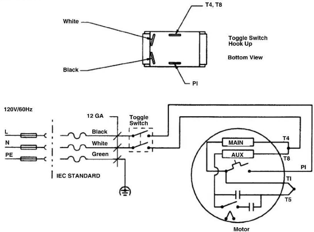
Wiring Diagrams
KJ-1350—120V
text_image
T4, T8 White Black PI Toggle Switch Hook Up Bottom View 120V/60Hz L N PE 12 GA Black White Green IEC STANDARD Toggle Switch T4 T8 PI MAIN AUX TI T5 MotorKJ-1750 — 120V
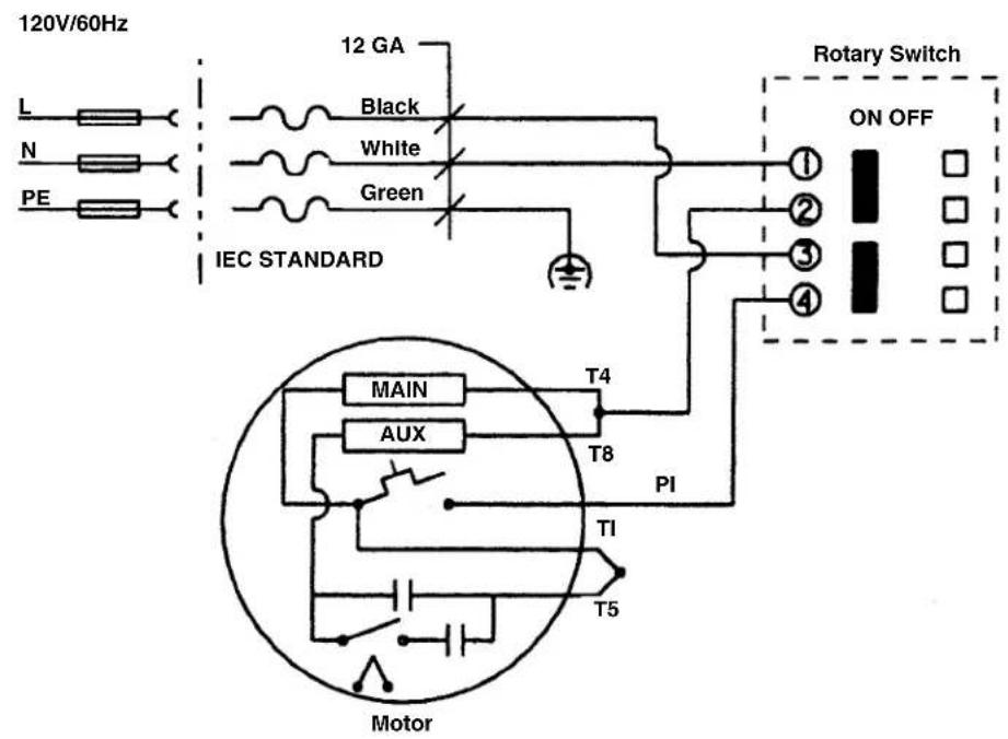
text_image
120V/60Hz L N PE 12 GA Black White Green IEC STANDARD Rotary Switch ON OFF ① ② ③ ④ T4 T8 PI MAIN AUX TI T5 MotorRidge Tool Company 13
KJ-1750-Export — 230V
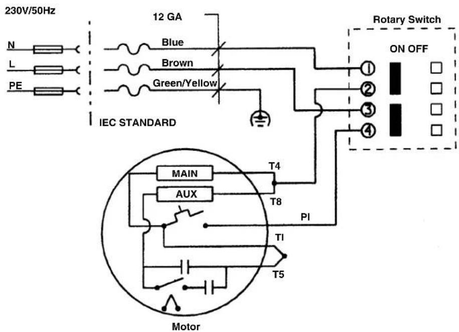
text_image
230V/50Hz N L PE 12 GA Blue Brown Green/Yellow IEC STANDARD Rotary Switch ON OFF ① ② ③ ④ T4 T8 PI T1 T5 MotorChariots de transport ....21
Inspection de la machine....21
natural_image
Mechanical pressure pump assembly with motor, wheels, and pressure gauges (no visible text or symbols)natural_image
Silhouette of a person running with a flag, no text or symbols present
natural_image
Black starburst symbol on white background (no text or symbols)natural_image
Close-up of a hand adjusting a mechanical valve component (no visible text or symbols)natural_image
Close-up of hands holding a tool with multiple connectors (no text or symbols visible)natural_image
Three black-and-white pictograms showing a helmet, a person running with a flag, and a person running with a rope (no text or symbols)natural_image
Close-up of a hand adjusting a mechanical valve with a pressure gauge (no visible text or symbols)natural_image
Close-up of a mechanical valve assembly with no visible text or symbolsnatural_image
Close-up of a mechanical valve assembly with no visible text or symbolsTechnical Service Department
400 Clark Street
Elyria, Ohio 44035-6001
natural_image
Mechanical pressure pump assembly with motor, wheels, and attached cylindrical component (no visible text or symbols)Machine and Work Area Set-Up
ADVERTENCIA

natural_image
Silhouette of a person in motion holding a pointer (no text or symbols)
natural_image
Black jagged explosion symbol on white background (no text or symbols)natural_image
Close-up of a hand adjusting a mechanical valve assembly (no visible text or symbols)natural_image
Close-up of hands using a tool to connect two connectors (no text or symbols visible)natural_image
Close-up of a hand adjusting a pipe valve with a digital pressure gauge (no visible text or symbols)natural_image
Close-up of a metallic industrial valve assembly with multiple ports and mounting base (no visible text or symbols)natural_image
Close-up of a mechanical valve assembly with no visible text or symbolsTechnical Service Department
400 Clark Street
Elyria, Ohio 44035-6001
RIDGID® tools are warranted to be free of defects in workmanship and material.
How long coverage lasts
This warranty lasts for the lifetime of the RIDGID ^® tool. Warranty coverage ends when the product becomes unusable for reasons other than defects in workmanship or material.
How you can get service
To obtain the benefit of this warranty, deliver via prepaid transportation the complete product to RIDGE TOOL COMPANY, Elyria, Ohio, or any authorized RIDGID® INDEPENDENT SERVICE CENTER. Pipe wrenches and other hand tools should be returned to the place of purchase.
What we will do to correct problems
Warranted products will be repaired or replaced, at RIDGE TOOL'S option, and returned at no charge; or, if after three attempts to repair or replace during the warranty period the product is still defective, you can elect to receive a full refund of your purchase price.
What is not covered
Failures due to misuse, abuse or normal wear and tear are not covered by this warranty. RIDGE TOOL shall not be responsible for any incidental or consequential damages.
How local law relates to the warranty
Some states do not allow the exclusion or limitation of incidental or consequential damages, so the above limitation or exclusion may not apply to you. This warranty gives you specific rights, and you may also have other rights, which vary, from state to state, province to province, or country to country.
No other express warranty applies
This FULL LIFETIME WARRANTY is the sole and exclusive warranty for RIDGID ^® products. No employee, agent, dealer, or other person is authorized to alter this warranty or make any other warranty on behalf of the RIDGE TOOL COMPANY.

Ce qui est couvert
Elyria, Ohio 44035-6001
U.S.A.