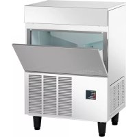
F 125 - Ice machine BARTSCHER - Free user manual and instructions
Find the device manual for free F 125 BARTSCHER in PDF.



| Product Type | Nugget Ice Machine |
| Brand | Bartscher |
| Model | F 125 |
| Ice Production (max) | Up to 125 kg/24h |
| Ice Bin Capacity | 20 kg |
| Power Supply | 220-240 V ~ 50 Hz single-phase |
| Power Consumption | 480 W |
| Current Draw | 3.2 A |
| Refrigerant | R134a |
| Refrigerant Charge (air/water) | 400 g / 300 g |
| Condensation Type | Air or Water |
| Ambient Operating Temperature | 10 to 40 °C |
| Water Supply Temperature | 5 to 40 °C |
| Minimum Water Pressure | 1 bar |
| Body Material | Stainless Steel |
| Control Type | Electronic with Microprocessor |
| LED Indicators | Power, alarms, water level, bin full |
| Safety System | Automatic shutdown in case of anomaly (rotation, temperature, water) |
| Cleaning | Descalable hydraulic circuit, condenser cleaning recommended |
| Periodic Maintenance | Check upper bearing every 6 months |
Frequently Asked Questions - F 125 BARTSCHER
User questions about F 125 BARTSCHER
0 question about this device. Answer the ones you know or ask your own.
Ask a new question about this device
Download the instructions for your Ice machine in PDF format for free! Find your manual F 125 - BARTSCHER and take your electronic device back in hand. On this page are published all the documents necessary for the use of your device. F 125 by BARTSCHER.
USER MANUAL F 125 BARTSCHER
RAFFR. AD ACQUA/WATER COOLED
WASSERGEKÜHLT/REFB. A EAU
REFR.A AGUA
Temperatura acqua/Water temperature
Wassertemperature/ Temperature equation Temperature aquae
| ℃ | 32° | 21° | 15° | 10° | |
| 10° | 76 | 81 | 84 | 86 | kg |
| 21° | 72 | 77 | 80 | 82 | kg |
| 32° | 68 | 74 | 76 | 78 | kg |
| 38° | 64 | 70 | 71 | 72 | kg |
Tnnnne aannnne
aannnnnne aannnnnne
Tannnnnne nnnnne aannnne
( x - 2x) t - xy^2 = ( xt^2 - 1) x + 2xy^2
RAFFR. AD ARIA/AIR COOLED
LUFTGEKUHLT/REFR.A AIR
REFR.AIRE
Temperatura acqua/Water temperature
Wassertemperatur/Temperature eau
Temperatura agua
| ℃ | 32° | 21° | 15° | 10° | |
| 10° | 78 | 84 | 87 | 90 | kg |
| 21° | 72 | 78 | 81 | 84 | kg |
| 32° | 58 | 63 | 66 | 68 | kg |
| 38° | 48 | 52 | 54 | 56 | kg |
Prod. ghlaccio In 24 h/ice prod. per 24 h
Specification SF 300 8
Specification SF 500 9
Specification SFN 1000 10
GENERAL INFORMATION AND INSTALLATION
Introduction 11
Unpacking and Inspection - Ice maker 11
Unpacking and Inspection - Storage bin 11
Location and levelling 12
Electrical connections 13
Water supply and drain connection 13
Finalcecklist 13
Installationpractice 14
OPERATING INSTRUCTIONS
Start up 15
Operations checks 17
PRINCIPLE OF OPERATION (how it works)
Water circuit 20
Refrigerant circuit 21
Mechanical system 23
Operating pressures 24
Components description 25
ADJUSTMENT, REMOVAL AND REPLACEMENT PROCEDURES
Adjustment of the evaporator water level 29
Replace of the gear motor magnetic sensor 29
Replace of auger, water seal, bearing and coupling 29
Replacement of the gear motor assay 30
Replacement of freezing cylinder 31
Wiring diagram 32
Service diagnosis 36
MAINTENANCE AND CLEANING INSTRUCTIONS
General 38
Icemakers 38
Cleaning instructions of water system 38
TECHNICAL SPECIFICATION
ELECTRONIC MODULAR
FLAKERS mod. F80 (R 134a)
| Produzione di ghiaccio in 24 ore sono a Ice produced for 24 hours up to Elsproduktion in 24 Stunden bis zu | kg. 90 |
| Production de glace en 24 h jusqu'à | |
| Produccion de hielo en las 24 horas hasta | |
| Raffreddamento unità condensatrice arla o acqua: consumo n. 20 litri per ora* | |
| Condensing unit cooling air or water: consumption n. 20 litres per hour* | |
| Kondensatorenhelt Luft oder Wasser: Verbrauch n. 20 liters pro Stunde* | |
| Refroidissement de l'unité de condensation air ou eau: consommation n. 20 litres par heures* | |
| Refrigeración de launidad condensadora aire o agua: consumo n. 20 litres para hora* | |
| Potenza assorbita/Absorbed power/Leistungsaufnahme | W 400 |
| Puisance absorbée/Potencia Absorbida | |
| Refrigerante/Refrigerant/Kältemittel | R 134a |
| Réfrigérant/Refrigerant | |
| Attacco entrata acqua/Water inlet connection | 3/4" Gas |
| Anschluss für Wasserzufluss/Prise entree d'eau/conexión entrada agua | |
| Attacco scarlico acqua/Water output connection | mm. Ø 20 |
| Anschluss für Wasserabfluss/Prise écoulement d'eau | |
| Conexión desague | |
| Alimentazione monofase/Single phase input/ Einhasige Spannung/Alimentation monophase | 220V-240V - 50 Hz |
| Alimentación monofásica | |
| Alimentazione voltaggi speciali: a richiesta | |
| Extra voltages: on request | |
| Andere Spannungen: Lieferbar auf Wunsch | |
| Alimentation voltages spéciaux: | sur besoin |
| Otros voltajes espéciales: | según pedido |
| Capacità deposito - Storage bin capacity | kg. 20 |
| Inhalt des Vorrats-Eisbehänders | |
| Capacité de la réserve - Capacidad del deposito | |
| Carrozzeria | |
| External structure | inox |
| Ausbührung | |
| Carrosserie | |
| Carroceria | |
| Peso netto/Net weight/Netto Gewicht | kg. 53 |
| Poids net/Peso neto |
(*) con temperatura acqua 15^
with water temperature 15^
mit Wassertemperatur 15 °C
avec temperature eau 15^
con temperatura agua 15 °C
Temperatura ambienta
Prrnnnne
Temperatures and ambient conditions
( x - 2x) t - xy^2 = ( xt^2 - 1) x + 2xy^2
PRODUZIONE DI GHIACCIO
ICE PRODUCTION
EIS PRODUktion
PRODUCTION DE GLACE
PRODUCION DE HIELO
RAFFR. AD ACQUA/WATER COOLED
WASSERGEKUHLT/REFR.A EAU
REFR.A AGUA
Temperatura acqua/Water temperature
Wassertemperature/ Temperature eau
Temperatura agua
| ℃ | 32° | 21° | 15° | 10° | |
| 10° | 76 | 81 | 84 | 86 | kg |
| 21° | 72 | 77 | 80 | 82 | kg |
| 32° | 68 | 74 | 76 | 78 | kg |
| 38° | 64 | 70 | 71 | 72 | kg |
rrnne aee
Prrnnnne
Tnrrnnnne aannnnnne
( x - 2x) t - xy^2 = ( xt^2 - 1) x
RAFFR. AD ARIA/AIR COOLED
LUFTGEKÜHLT/REFR. A AIR
REFR.A AIRE
Temperatura acqua/Water temperature
Wassertemperatur/Temperature eau
Temperatura agua
| °C | 32° | 21° | 15° | 10° | |
| 10° | 78 | 84 | 87 | 90 | kg |
| 21° | 72 | 78 | 81 | 84 | kg |
| 32° | 58 | 63 | 66 | 68 | kg |
| 38° | 48 | 52 | 54 | 56 | kg |
Prod. ghlaccio In 24 h/ice prod. per 24 h
Temperatures ange temperature
PRODUZIONE DI GHIACCIQ
ICE PRODUCTION
EIS PRODUktion
PRODUCTION DE GLACE
PRODUCION DE HIELO
RAFFR. AD ACQUA/WATER COOLED
WASSERGEKÜHLT/REFR. A EAU
REFR.A AGUA
Temperatura acqua/Water temperature
Wassertemperature/temperature eau Temperatureaigua
| ℃ | 32° | 21° | 15° | 10° | |
| 10° | 97 | 108 | 117 | 120 | kg |
| 21° | 95 | 105 | 115 | 117 | kg |
| 32° | 90 | 100 | 107 | 110 | kg |
| 38° | 87 | 97 | 102 | 105 | kg |
Tempera nate Ambient temperature
raannnnnne aannnnnne
Tnrrnnnne aannnnne
RAFFR. AD ARIA/AIR COOLED
LUFTGEKÜHLT/REFR. A AIR
REFR.A AIRE
Temperatura acqua/Water temperature
Wassertemperatur/Temperature eau
Temperatura agua
| °C | 32° | 21° | 15° | 10° | |
| 10° | 102 | 111 | 115 | 120 | kg |
| 21° | 95 | 104 | 108 | 110 | kg |
| 32° | 84 | 90 | 94 | 97 | kg |
| 38° | 75 | 81 | 85 | 87 | kg |
Prod. ghlaccio In 24 h/ice prod. per 24 h
GENERAL INFORMATION AND INSTALLATION
A INTRODUCTION
the step-by-step procedures for the installation, start- up and operation, maintenance and cleaning for the F80 - F125 Modular Icemakers.
The Electronic Flakers and Superflakers are quality designed, engineered and manufactured. Their ice making systems are thoroughly tested providing the utmost in flexibility to fit the needs of a particular user.
B. UNPACKING AND INSPECTION Icemaker
1 Call you rauthorizedl Distributor or Dealer for proper installation.
2 Visually inspect the exterior of the packing and skid. Any severe damage noted should be reported to the delivering carrier and a concealed damage claimformfilled in subject to inspection of the contents with the carrier's representative present.
3 a) Cut and remove the plastic strip securing the carton box to the skid.
b) Cut open the top of the carton and remove the polystyre protection sheet.
NOTE. To retain the safety and performance built into this icemaker, it is important that installation and maintenance be conducted in the manner outlined in this manual.
c) Pull out the polystyre posts from the corners and then remove the carton.
d) Lift the whole carton and pull it out from the device.
4 Remove top and sides panels of the unit and inspect for any concealed damage. Notify carrier of your claim for the concealed damage as stated in step 2 above.
5 Remove all internal support packing and masking tape.
6 Check that refrigerant lines do not rub against or touch other lines or surfaces, and that the fan blades move freely.
7 Check that the compressor fits snugly onto all its mounting pads.
8 See data plate on the rear side of the unit and check that local main voltage corresponds with the voltage specified on it.
C. LOCATION AND LEVELLING
WARNING. This Modular Flaker and Superflaker is designed for indoor installation only. Extended periods of operation at temperature exceeding the following limitations will constitute misuse under the terms of the Manufacturer's Limited Warranty resulting in LOSS of warranty coverage.
1 Position the storage bin in the selected permanent location. Criteria for selection of location include:
a) Minimum room temperature 10^ (50^) and maximum room temperature 40^ (100^) .
b) Water inlet temperatures: minimum 5^ (40^) and maximum 35^ (90^) .
c) Well ventilated location for air cooled models (clean the air cooled condenser at frequent intervals).
d) Service access: adequate space must be left for all service connections through the rear of the ice maker.
A minimum clearance of 15cm (6") must be left at the sides of the unit for routing cooling air drawn into and exhausted out of the compartment to maintain proper condensing operation of air cooled models.
2 Level the Storage Bin Assy in both the left to right and front to rear directions by means of the adjustable legs.
NOTE: This ice flake maker contains sensitive and highly precise parts. Knocks and heavy blows must therefore be avoided.
D. ELECTRICAL CONNECTIONS
See data plate for current requirements to determine wire size to be used for electrical connections. All icemakers require a solid earth wire.
All ice machines are supplied from the factory completely pre-wired and require only electrical power connections to the wire cord provided at the rear of the unit.
Make sure that the ice machine is connected to its own circuit and individually fused (see data plate for fuse size).
The maximum allowable voltage variation should not exceed -10% and +10% of the data plate rating. Low voltage can cause faulty functioning and may be responsible for serious damage to the overload switch and motor windings.
NOTE. All external wiring should conform to national, state and local standards and regulations.
Check voltage on the line and the ice maker's data plate before connecting the unit.
E. WATER SUPPLY AND DRAIN CONNECTIONS
When choosing the water supply for the ice flaker consideration should be given to:
a) Length of run
b) Water clarity and purity
c) Adequate water supply pressure
Since water is the most important single ingredient in producing ice you cannot emphasize too much the three items listed above.
Low water pressure, below 1 bar may cause malfunction of the ice maker unit.
Water containing excessive minerals will tend to produce scale build-up on the interior parts of the water system while too soft water (with too lo contents of mineral salts), will produce a very hard flaker ice.
ATTENTION. The use of fully hardened water (without or nearly without mineral salts) with electric cable capability of under 30~ S blocks the flow of low voltage electricity between the lowest sensors in the swimming pool and therefore causes the device to be switched off or to stop working
Dark chlorinated or iron-containing water can be improved through the active carbon filter
If water contains a high level of impurities, it is advisable to consider the installation of an appropriate water filter or conditioner.
WATER SUPPLY
Connect the 3/4'' GAS male of the water inlet fitting, using the foodgradeflexible hosesupplied to the coldwater supply linewith regular plumbing fitting and a shut-off valve installed in an accessible position between the water supply line and the unit.
If water contains a high level of impurities, it is advisable to consider the installation of an appropriate water filter or conditioner.
WATER SUPPLY - WATER COOLED MODELS
The water cooled versions of Ice Makers require two separate inletwater supplies, one for the water making the flaker ice and the other for the water cooled condenser.
Connect the 3/4'' GAS male fitting of the water inlet, using the flexible hose supplied to the cold water supply linewith regular plumbing fitting and a shut-off valve installed in an accessible position between the water supply line and the unit.
WATER DRAIN
The recommended drain tube is a plastic or flexible hose with 18mm(3/4^ ) I.D. which runs to an open trapped and vented drain. When the drain is a long run, allow 3 cm pitch per meter (1/4" pitch per foot). Install a vertical open vent on drain line high point at the unit drain connection to ensure good draining.
Theidealdrainreceptacleisatrappedandvented floor drain.
WATER DRAIN - WATER COOLED MODELS
Connect the 3/4'' GAS male fitting of the condenser water drain, utilizing a second flexible hose to the open trapped and vented drain.
This additional drain linemust not interconnect to any other of the units drains.
NOTE. The water supply and the water drain must be installed to conform with the local code. In some case a licensed plumber and/or a plumbing permit is required.
F. FINAL CHECK LIST
1 Is the unit in a room where ambient temperatures are within a minimum of 10^ (50^) even in winter months?
2 Is there at least a 15 cm (6") clearance around the unit for proper air circulation?
3 Is the unit level? (IMPORTANT)
4 Have all the electrical and plumbing connections been made, and is the water supply shut-off valve open?
5 Has the voltage been tested and checked against the data plate rating?
6 Has the water supply pressure been checked to ensure a water pressure of at least 1 bar (14 psi). been checked to ensure that the compressor is snugly fitted onto the mounting pads?
8 Check all refrigerant lines and conduit lines to guard against vibrations and possible failure.
9 Have the bin liner and cabinet been wiped clean?
10 Has the owner/user been given the User Manual and been instructed on the importance of periodic maintenance checks?
11 Has the Manufacturer's registration card been filled in properly? Check for correct model and serial number against the serial plate and mail the registration card to the factory.
12 Has the owner been given the name and the phone number of the authorized Service Agency serving him?
G. INSTALLATION PRACTICE
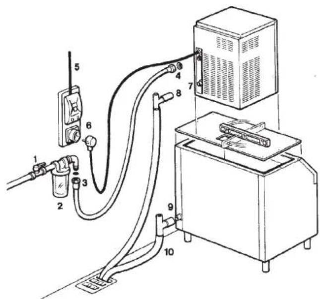
1 Hand shut-off valve
2 Water filter
3 Water supply line
4 3/4" GAS male fitting
5 Power line
6 Main switch
7 Drain fitting
8 Vented drain
9 Vented drain
10 Open trapped vented drain
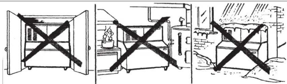
WARNING. This icemaker is not designed for outdoor installation and will not function in ambient temperatures below 10^ (50^) or above 40^ (100^) . This icemaker will malfunction with water temperatures below 5^ (40^) or above 35^ (90^) .
OPERATING INSTRUCTIONS
STARTUP
After having correctly installed the ice maker and completed t he plumbing and electrical connections, perform the following "Start-up" procedure.
A. Open the water supply line shutoff valve and put the unit under electrical power by moving the main switch, on the power supply line, to the ON position.
The first LED - GREEN - will glow to signal that unit is under power.
NOTE. Every time the unit is put under power, after being kept for sometime in shut-off conditions (electrically disconnected) the RED LED will blink for 3 minutes (60^ on MF 66 only) after which the unit will start up with the immediate operation of the gear motor assembly and, after few seconds, of the compressor (Fig.1).
B. Elapsed the stand by period the unit starts operating with the activation in sequence of the following assemblies:
GEAR MOTOR/S
COMPRESSOR
FAN MOTOR/S (if unit is an air cooled version) kept under control by the condenser temperature sensor which has its probe within the condenser fins (Fig.2).
C. After 2 or 3 minutes from the compressor start up, observe that flaker ice begins dropping off the ice spout to fall through the ice chute into the storage bin.
NOTE. The first ice bits that drop into the ice storage bin are not so hard as the evaporating temperature has not yet reached the correct operating value. It is necessary to allow the ice - just made - to cure itself and wait for about ten minutes for the evaporating temperature to reach the correct value so to make more hard bits of ice.
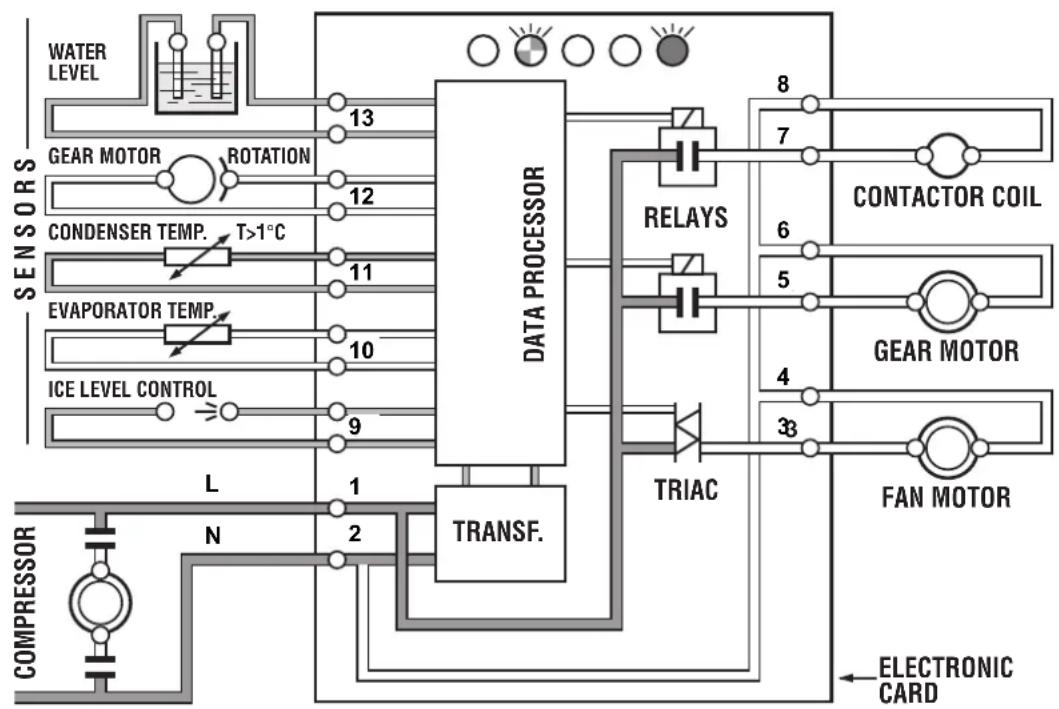
FIG.1
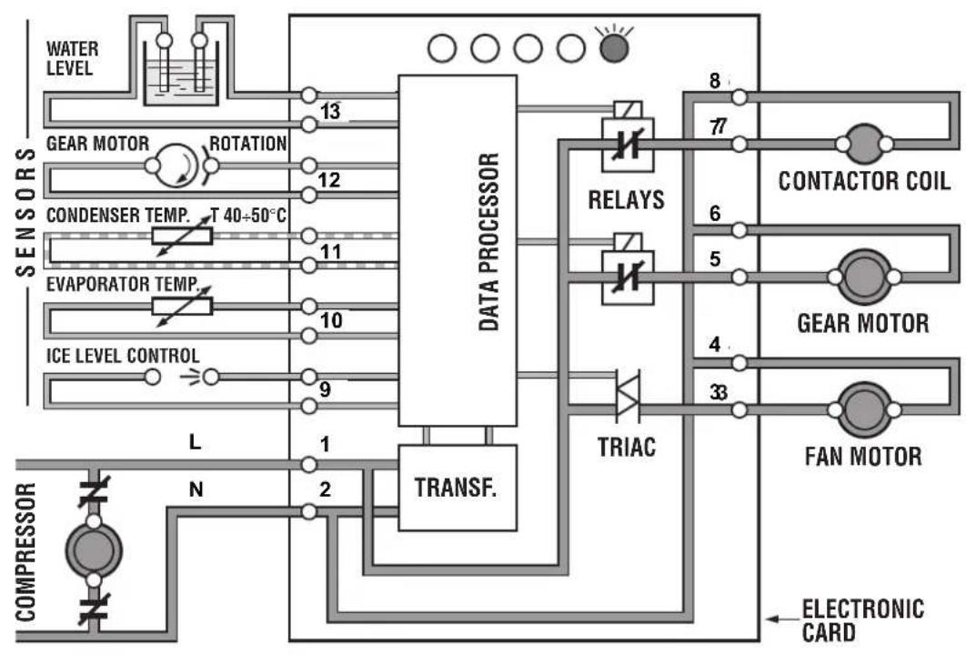
FIG.2
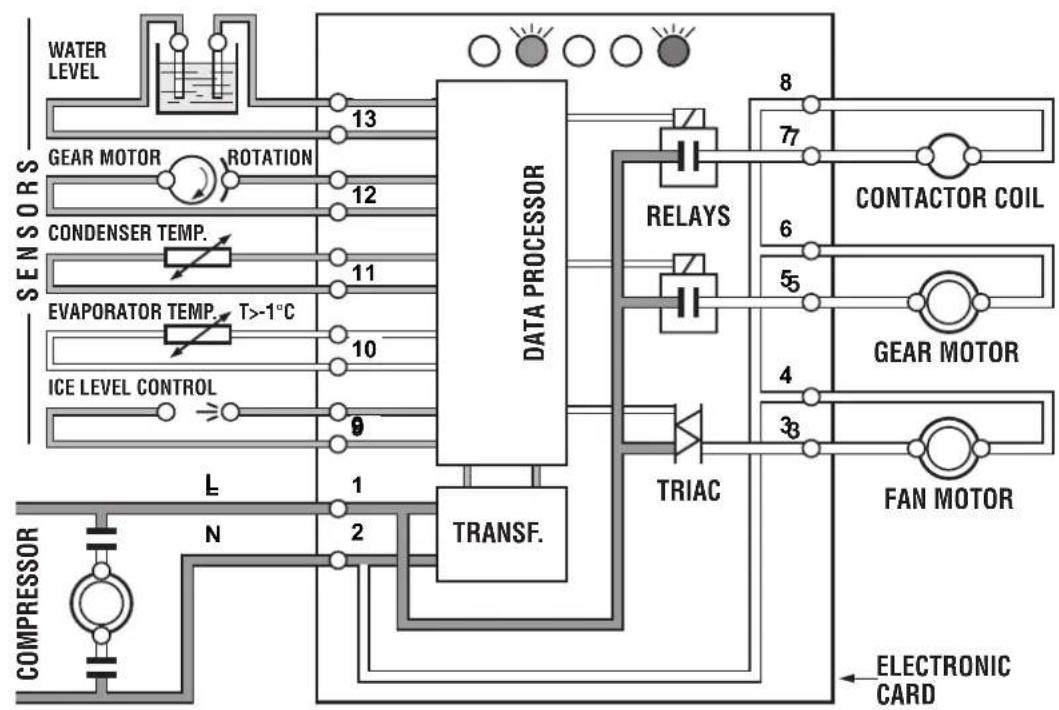
FIG.3
NOTE. If, after ten minutes from the compressor start-up, the evaporating temperature has not dropped down to a value lower than -f C (30 F) the evaporating temperature sensor detects such an abnormal situation and stops consequently the unit operation (first the compressor and 3' later the gear reducer).
In this circumstance, the 5th warning YELLOW LED will blink.

The machine will remain in OFF mode for one hour then it will restart automatically. In case the unit trips OFF again in alarm for 3 times in 3 hours, the machine SHUTS OFF DEFINITIVELY.
After having diagnosed and eliminated the cause of the too hi evaporating temperature (insufficient refrigerant in the system or compressor not running) it is necessary to unplug and plug in again to restart machine. The unit, before resuming the normal operation, will go through the usual 3 minutes STAND-BY period.
the
D. Remove front service panel and, if necessary, install the refrigerant service gauges on the corresponding service valves to check both the HI and LO refrigerant pressures.
NOTE. On air cooled models, the condenser temperature sensor, which is located within the condenser fins, keeps the head (condensing) pressure between preset values.
In the event of condenser clogged - such to prevent the proper flow of the cooling air-or, in case the fan motor is out of operation, the condenser temperature rises and when it reaches 70^ (160^) for air cooled version and 60^ (140^) - for water cooled version the condenser temperature sensor shuts-off the ice maker (first the compressor and 3^ later the gear reducer) with the consequent light-up of the RED WARNING LIGHT(Fig.3).

The machine will remain in OFF mode for one hour then it will restart automatically. In case the unit trips OFF again in alarm for 3 times in 3 hours, the machine SHUTS OFF DEFINITIVELY.
After having diagnosed the reason of the temperature rise and removed its cause, it is necessary to proceed as per the previous "NOTE" to start up again the operation of the ice maker.
E. Check for the correct CUT-OUT and CUT-IN of the water levelsensor by first shutting closed the water shutoff valve on the water supply line.
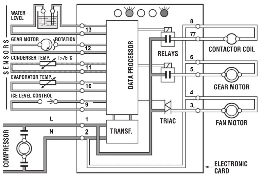
FIG. 4
This will cause a gradual decrease of the water level in the float reservoir and as soon as the level gets below the two vertical metal pins, the flaker stops to operate (compressor first and 3' later the gear reducer) and the YELLOW warning LED will glow to signal the shortage of water (Fig.4)

NOTE. The water level sensor detects the presence of water in the float reservoir and confirms it to the micro processor by maintaining a low voltage current flow between the two metal pins using the water as conductor.
WARNING. The use of de-mineralized water (water with no salt content) having an electrical conductivity lower than 30 S , will cause break with the consequent CUT-OUT of the flaker and the glowing of the YELLOW LED of water shortage, even with water in the reservoir.
Opening the water supply line shutoff valve to fill up again the float reservoir, the YELLOW LED goes off while the RED LED starts blinking.
After 3 minutes the unit resumes its total operation with the immediate start-up of the gear motor and, few seconds later, of the compressor.
F. Check for the correct operation of the electronic eye (one per each ice chute on mode MF 66) of the optical ice level control, by closing the bottom opening of the vertical ice chute. Wait the built up of the ice into the ice chute till cuts the light beam of the sensing "eyes". This interruption will cause an immediate blinking of the Bin Full YELLOW LED located on the fro of the P.C. Board and after about 6 secor causes the shutoff of the unit (compressor first and 3^ later the gear reducer) with the simultaneous lighting (steady) of the Same LED signalling the full bin situation (Fig.5).

Discharge the ice from the ice chute so to resur the light beam previously interrupted (YELLOW LED blinking fast) and after about 6 seconds the flaker will re-start -through the 3 minutes STANDBY period-with the extinguishing of the YELLOW LED.
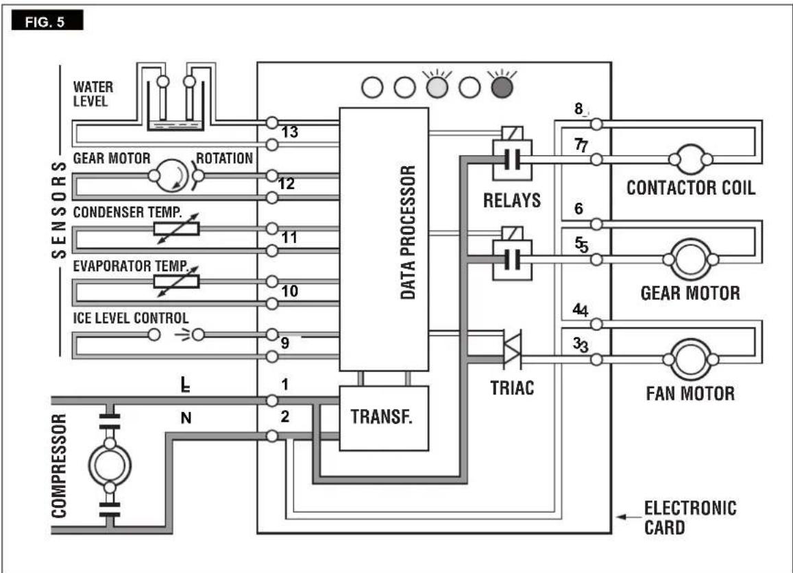
NOTE. The ICE LEVEL CONTROL (INFRARED SYSTEM) is independent of the temperature however, the reliability of its detection can be affected by external light radiations or by any sort of dirt and scale sediment which may deposit directly on the light source and on the receiver. To prevent any possible ice maker malfunction, it is advisable to locate the unit where it can't be reached by any direct light beam or light radiation and to follow the instructions for the periodical cleaning of the light sensor elements as detailed in the MAINTENANCE AND CLEANING PROCEDURES.
NOTE. In the front of the PC Board is located a small I/R Trimmer directly connected with the optical Ice level control. By means of its screw it is possible to modify the signal received from the Ice Level control so to overcame some problem caused by dirt and/or low power supply. When adjusted it is very important to check for its correct operation using ice (NOT HAND) to break the Infrared Beam. In case the machine doesn't stop it means that the new setting is too much powerful and need to be reduced always by means of the I/R Trimmer.
M. If previously installed, remove the refrigerant service gauges and re-fit the unit service panels previously removed.
N. Instruct the owner/user on the general operation of the ice machine and about the cleaning and care it requires.
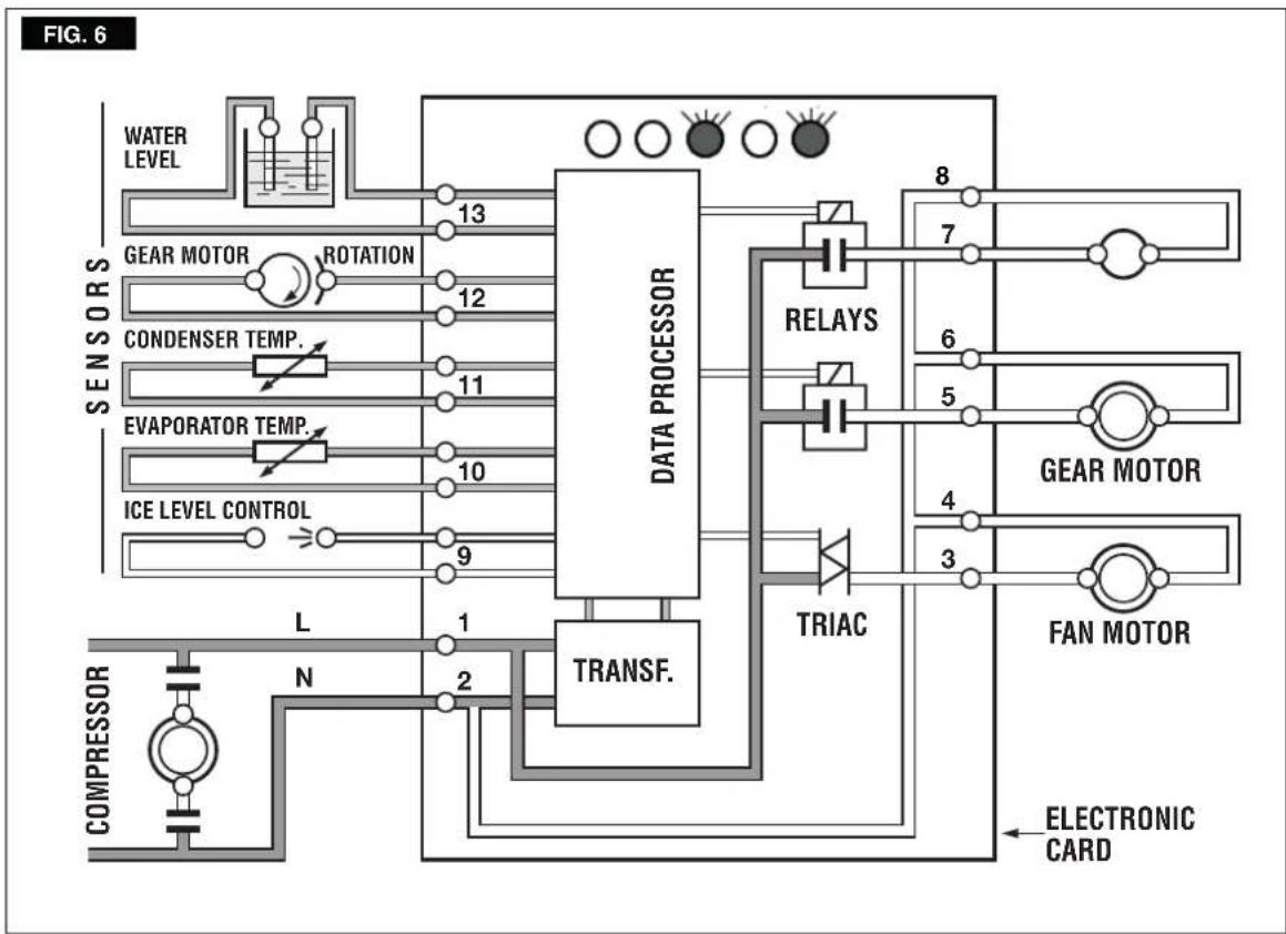
The water enter in the machine through the water inlet fitting which incorporates a strainer - located at the rear side of the cabinet - then it goes to the water reservoir flowing through a float valve.
NOTE. The presence of the water in the float reservoir is detected by a system of two sensors which operates in conjunction with the P.C. Board. The two sensors use the water as a conductor to maintain a low voltage current flow between them. In case the water used is very soft (de-mineralized) or the float reservoir gets empty the current flow between the sensors become so weak or is no longer maintained that, as consequence, the P.C. Board shutoff the flaker operation with the simultaneous glowing of the YELLOW LED signalling "Shortage of water".
The float reservoir is positioned at the side of the freezing at such an height to be able to maintain a constant water level. The water flows from the reservoir into the bottom inlet of the freezer to surround the stainless steel auger which is vertically fitted in the center of the freezer.
In the freezer the incoming water gets chilled into soft (slush) ice which is moved upward by the rotating action of the auger. The auger rotates counterclockwise within the freezer powered by a direct drive gear motor and carries the ice upward along the refrigerated freezer innerwalls andbydoingso theice gets progressively thicker and harder.
FLOAT TANK
FLOAT VALVE
FLOAT TANK
FLOAT VALVE
FREEZER
WATER INLET LINE
FREEZER WATER
FEED LINE
FLOAT TANK
ICE SPOUT
FLOAT VALVE
FREEZER
WATER INLET LINE
FREEZER
WATER
FEED LINE
The ice, being costantly lifted up, meet the teeth of the ice breakerwhich is fitted on the top end of the auger,where it gets compacted, cracked and forced to change from vertical into horizontal motion to be discharged out, through the ice spout and chute, into the storage bin.
By running the ice maker, i.e. by putting the unit under power, starts the automatic and continuous icemaking process which would not stop until the ice storage bin gets filled-up to the level of the control "eyes" located on the ice chute. As the ice level raises to interrupt the light beam running between the two infrared leds, the unit stops after six seconds (compressor first and 3' later the gear reducer), with the simultaneous glowing of the YELLOW LED signalling the "Full Bin" situation.
NOTE. The interruption of the light beam between the two light sensors is immediately signalled by the blinking of the BIN FULL YELLOW LED located on the front of the P.C. Board.
After about 6" of steady interruption of the light beam the unit stops and the "Full Bin" YELLOW LED glows steady.
The six seconds of delay prevent the unit from stopping for any undue reason like the momentarily interruption of the light beam caused by the flakes that slides along the ice spout before dropping into the bin.
As some ice gets scooped out from the storage bin, the light beam between the two sensors resumes (fast blinking of YELLOW LED) and six seconds later the ice machine restarts the ice making process - going always through the 3' stand by - and the YELLOW LED goes off.
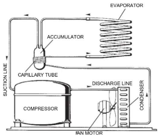
REFRIGERANT CIRCUIT
The hot gas refrigerant discharged out from the compressor reaches the condenser where, being cooled down, condenses into liquid.
Flowing into the liquid line it passes through the drier filter, then it goes all theway throughtca-pillary tubewhere it looses some of its pressure so that its pressure and temperature are lowered. Next, the refrigerant enters into the evaporator coil wrapped around the freezer inner tube.
The water being constantly fed at the interior of thefreezer inner tube,exchange heat with the refrigerant circulating into the evaporator coil, this cause the refrigerant to boil-off and evaporate, there by it changes from liquid into vapor.
The vapor refrigerant then passes through the
suction accumulator and through the suction line where the refrigerant exchanges heat with the one flowing into the capillary tube (warmer) before beingsucked into the compressor to be recirculated.
The refrigerant head pressure is kept between two pre-set values (8÷9 bar - 110÷125 psig on F120) by the condenser temperature sensor which has its probe located within the condenser fins - in air cooled versions.
This condenser temperature sensor, when senses a rising of the condenser temperature beyond the pre-fixedlimit, changes its electrical resistance and send a low voltage power flow to the MICROPROCESSOR of the P.C. Board which energizes, through a TRIAC, the Fan Motor in ON-OFF mode.
On the water cooled versions, the refrigerant head pressure is kept at the constant value of 8.5 bar (120 psig) on F120 by themetered amount of water passing through the condenser which is regulated by the action of the Water Regulating Valve that has its capillary tube connected to the liquid refrigerant line. As pressure increases, the water regulating valve opens to increase the flow of cooling water to the condenser.
NOTE. In case the condenser temperature probe senses that the condenser temperature has risen to 70^ on air cooled version - or 60^ Conwater cooled version - for one of the following abnormal reasons:
CLOGGED CONDenser (Air cooled version) INSUFFICIENT FLOW OF COOLING
WATER (Water cooled version)
FAN MOTOR OUT OF OPERATION (Air cooled version)
AMBIENT TEMPERATURE HIGHER THEN 43^ (110°F)
it causes the total and immediate SHUT-OFF of the machine (compressor first and gear motor 3' later) in order to prevent the unit from operating in abnormal and dangerous conditions.
When the ice maker stops on account of this protective device, there is a simultaneous glowing of the RED LED, warning the user of the Hi Temperature situation.
The machine will remain in OFF mode for one hour then it will restart automatically.
In case the unit trips OFF again in alarm for 3 times in 3 hours, the machine SHUTS OFF DEFINITIVELY.
After having eliminated the source of the excessive condenser temperature, to restart the ice-machine it is necessary to unplug and plug in again.
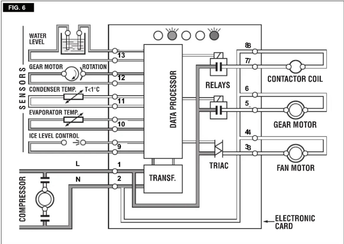
The RED LED starts blinking and three minutes later the flaker unit resume its normal operating mode. The condenser temperature sensor has a further safety function which consist in preventing the unit from operating in Lo-ambient conditions i.e. when the condenser temperature - equivalent to the ambient temperature - is lower then 1^ 34^ (Fig.6).
As soon as the ambient temperature rises up to 5^ the P.C. Board restarts automatically the machine on the three minutes starting time.
The refrigerant suction or Lo-pressure sets - in normal ambient conditions - on the value of 0.5 bar (7 psig) on F120 after few minutes from the unit start-up.
This value can vary of 0.1 or 0.2 bar (1.5÷3 psig) in relation to the water temperture variations influencing the freezer cylinder.
NOTE. If, after ten minutes from the unit start up, no ice is made and the evaporating temperature detected by the evaporator sensor results to be higher than -1^ 30^ the ice maker stops (compressor first and gear motor 3 later) and the 5th WARNING YELLOW LED blinks.
The machine will remain in OFF mode for one hour then it will restart automatically. In case the unit trips OFF again in alarm for 3 times in 3 hours, themachine SHUTSOFF DEFINITIVELY.
MECHANICAL SYSTEM
The mechanical system of the Flaker machines consists basically of a gear motor assembly which drives, through a ratched coupling, a worn shaft or auger placed on its vertical axis within the freezing cylinder.
The gear motor is made of a single phase electric motor with a permanent capacitor. This motor is directly fitted in the gear case through which it drives - in counter clockwise rotation at a speed of 9.5 r.p.m. - the freezer auger being linked to it by the ratched coupling.
Too low ambient and water temperature (well below the limitations of respectively 10^ and 5^ - 50^ and 40^ ) or frequent interruptions of the water supply to the freezing cylinder (clogging of the water hose connecting the float reservoir to the water inlet at the bottom of the freezer) may cause the ice to get too hard and compact loosing fluidity and thereby seizing the auger.
This situation will put under excessive strain and load the entire drive system and freezer bearings.
NOTE. Before charging the refrigerant system always check the type of refrigerant and quantity as specified on the individual ice machine dataplate. The refrigerant charges indicated are relatives to averages operating conditions.
Refrigerant metering device:
Capillary tube
Gas charge (R 134a)
Air cooled Water cooled
F 80 300 gr 300 gr
F 125 400 gr 300 gr
Working pressure
(with 21^ ambient temperature)
Pression
discharge 8 ÷ 9 bar 8 ÷ 5 bar
Pression
suction 0.5 bar 0.5 bar
Working pressure
(with 21^ ambient temperature)
Pression
discharge 17÷ 18 bar 17 bar
Pression
suction 2.5 bar 2.5 bar
COMPONENTS DESCRIPTION
A Evaporator temperature sensor
The evaporator sensor probe is inserted into its tube well, which is welded on the evaporator outlet line, it detects the temperature of the refrigerant on the way out from the evaporator and signals it by suppling a low voltage current flow to the P.C. Board.
According to the current received, the microprocessor let the ice maker to continue its operations or not. In case the evaporating temperature, after 10 minutes from the unit start-up, does not go below -1^ (30°F) the evaporator sensor signals to stop immediately the unit operation, with the blinking of the 5th Warning YELLOW LED.
NOTE. Themachinewill remainINOFFmode for one hour then it will restart automatically. In case the unit trips OFF again in alarm for 3 times in 3 hours, themachine SHUTSOFF DEFINITIVELY.
To restart the unit after the shutoff caused by the hi evaporating temperature, it is necessary to switch OFF and ON the power line main disconnect Switch.
B Water level sensor
This sensor consists of two small stainless steel rods vertically fitted on the inner face of the reservoir cover and electrically connected to the low voltage circuit of the P.C. Board. When the cover of the reservoir is positioned in its place the tips of both the rods dip into the reservoir water transmitting a low power current throu the same.
NOTE. In the event of shortage of water in the reservoir or, in case the water used is too soft (de-mineralized) to cause greater resistance to the current flow (electrical conductivity lower than 30 S ) this sensor system causes the shutoff of the machine, to protect it from running without water or with an inadequate water quality. In this situation the YELLOW LED will glow to warn of the machine shutoff and the reason why.
C Condenser temperature sensor
The condenser temperature sensor probe, located within the condenser fins (air cooled version) or in contact with the tube coil (water cooled version) detects the condenser temperature variations and signals them by supplying current, at low voltage, to the P.C. BOARD.
In case thecondenser temperaturesensordetects a temperature at the condenser lower than +3^ (37^) that means ambient temperature too low for the correct unit operation, the sensor signals to the P.C. BOARD to do not start up the unit till the ambient temperature rises to 10^ .
In the air cooled versions, in relation to the different current transmitted, the micro processor of the P.C. BOARD supplies, through a TRIAC, the power at high voltage to the fan motor.
In the event the condenser temperature rises and reaches 60^ or 70^ according to the setting of DIP SWITCH number 8 the current arriving to the micro processor is such to cause an immediate and total stop of the machine operation.
NOTE. The machine will remain in OFF mode for one hour then it will restart automatically. In case the unit trips OFF again in alarm for 3 times in 3 hours, themachine SHUTSOFF DEFI-NITIVELY.
To restart the unit after the shutoff caused by the hi condenser temperature, it is necessary to switch OFF and ON the power line main disconnect Switch.
D Electromagnetic sensor
This safety device is housed on top of the Drive Motor and detects - based on Hall Effect principle - the rotating speed and rotating direction of the drive Motor.
Should the rotating speed drop below 1300 r.p.m. the magnitude measured by this device is such to signal to the microprocessor to stop the unit and light-up the YELLOW LED. The same reaction occurs when the drive motor will tend to rotate inthewrongdirection(counterclockwise) or when it doesn't rotate at all.
NOTE. The machine will remain in OFF mode for one hour then it will restart automatically. In case the unit trips OFF again in alarm for 3 times in 3 hours, the machine SHUTS OFF DEFINITIVELY. To restart the unit after the shutoff caused by this safety device, it is necessary first to eliminate the cause that has generated the intervention of the device and then switch OFF and ON the power line main disconnect switch.
E Optical ice level control
The electronic optical ice level control, located into the ice chute has the function to stop the operation of the ice machine when the light beam between the light source and the receiver gets interrupted by the flake ice which accumulates in the chute.
When the light beam is interrupted the Bin Full YELLOW LED located in the front of the P.C. BOARD blinks; in case the light beam gets interrupted for as longer as 6 seconds, the ice machine stops with the glowing-up of the 2nd YELLOWLEDto monitor the full ice binsituation. The 6 seconds of delay prevents that any minimum interruption of the light beam due to the regular ice chuting through the ice chute may stop the operation of the unit.
As soon as the ice is scooped out (with the resumption of the light beam between the two infrared sensor of ice level control - YELLOW LED blinks fast) 6 seconds later the ice machine resumes its operation with the simultaneous extinguishing the 2nd YELLOW LED.
Resistive values Evaporatore probe
KTY 10.62
Resistive values Condenser probe
| T°C | Rmin | Rmax |
| -30 | 1223 | 1276 |
| -20 | 1345 | 1394 |
| -10 | 1474 | 1517 |
| 0 | 1611 | 1650 |
| 10 | 1757 | 1788 |
| 20 | 1910 | 1933 |
| 25 | 1990 | 2010 |
| 30 | 2067 | 2092 |
| 40 | 2226 | 2263 |
| 50 | 2395 | 2442 |
| 60 | 2569 | 2629 |
| 70 | 2752 | 2824 |
| 80 | 2941 | 3027 |
KTY 11.7
Characteristics of the optical sensor for flakes
| T°C | Rmin | Rmax |
| -30 | 1236 | 1301 |
| -20 | 1358 | 1422 |
| -10 | 1489 | 1547 |
| 0 | 1628 | 1683 |
| 10 | 1774 | 1824 |
| 20 | 1929 | 1972 |
| 25 | 2010 | 2050 |
| 30 | 2088 | 2134 |
| 40 | 2249 | 2308 |
| 50 | 2420 | 2490 |
| 60 | 2594 | 2681 |
| 70 | 2779 | 2880 |
| 80 | 2970 | 3087 |
Infra-red receiver (Photo transistor)
| Maximum voltage Vce | 35V |
| Maximum electricity Ic | 50 mA |
| Collector electricity whereby Ev=1000 1x, Vce=5V between 1 and 2 mA | |
| Operation temperature | -55°C ÷ +100°C |
Infra-red transmitter (Photo dioxide)
| Max. conversion voltage Vr | 5V |
| Maximum electricity If | 100 mA |
| Direct voltage Vr@100mA 25°C | = 1.5V |
| Operation temperature -55°C ÷ +100°C | |
F P.C. BOARD (Data processor)
The P.C. BOARD, fitted in its plastic box located in the front of the unit, consists of two separated printed circuits one at high and the other at low voltage and protected by fuses. Also it consists of five aligned LEDs monitoring the operation of the machine of three jumpers and of input terminals for the leads of the sensor probes as well as input and output terminals for the leads of the ice maker electrical wires. The P.C. BOARD is the brain of the system and it elaborates, through its micro processor, the signals received from the sensors in order to control the operation of the different electrical components of the ice maker (compressor, gear motor, etc.). The five LEDs, placed in a row in the front of the P.C. BOARD, monitor the following situations:
GREENLED
Unit under electrical power
YELLOW LED
Blinking: I/R beam cut out
Steady: storage bin full
YELLOW LED
Unit shut-off due to a too lo-water level into float tank

REDLED
ON all the time
Unit shut-off due to a too hi-condensing temperature
Unit shut-off due to a too lo-ambient temperature < + 1^
Blinking
3 minutes start up delay time
YELLOW LED
ON all the time
Unit shut-off due to the wrong rotation direction of gear motor
Unit shut-off due to the too lo speed of gear motor
Blinking
- Unit shut-off due to a too hi-evaporating temp.
> - 1^ after 10min of operation
YELLOW AND RED LED
- Blinking: Evaporator sensor out of order
Steady: Condenser sensor out of order
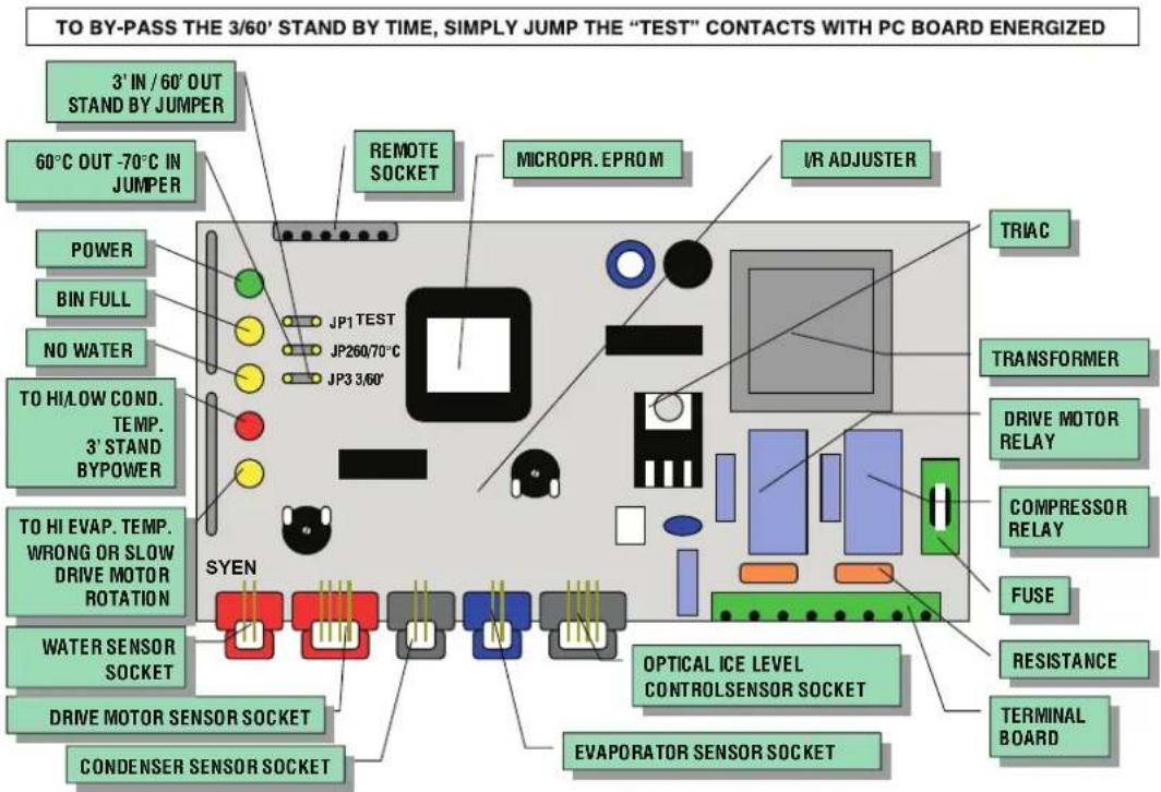
G Jumpers
TheFlakerPCBoardisequipped by threejumper: J1 · TEST: Used in the factory to energise all the electrical components duringthe Testing Mode. Used to by-pass the 3^ stand by time (just jumpthecontactswith PCBoard under power).
J2 - SYEN / J3 - Pro. El. Ind. - 60/70°C:
Used to set up the CutOut temperature of the condenser sensor:
- Jump OUT = 60°C
- Jump IN = 70°C
J3 - SYEN / J2 - Pro. El. Ind. - 3'/60':
Used to set up the start up delai time:
- Jump IN = 3'
- Jump OUT = 60'
H Float reservoir
The float reservoir consists of a plastic water pan on which is fitted a float valve with its setting screw. The float valve modulate the incoming water flow to maintain a constant water level in the reservoir, level that corresponds to the one in the freezing cylinder to ensure proper ice formation and fluidity.
On the inner side of the reservoir cover are fitted the twowater level sensor pinswhich detects the presence or the shortageof water inthereservoir.
NOTE. It is very important to make sure of the correct fitting of the cover on the reservoir in order to enable the sensor to efficiently control the water situation avoiding undue shutoff interventions.
1 Freezing cylinder or evaporator
The freezing cylinder ismade of a stainless steel vertical tube onwhich exterior iswrapped around the cooling coil with the evaporating chamber and in its interior is located the auger which rotates on its vertical axis and it is maintained aligned by the top and bottom bearings. A water seal system is located in the bottom part of the freezer while at the top end is fitted the ice breaker.
The water constantly flowing into the cylinder bottompart, freezes into ice when in contact with the cylinder inner walls. The ice is then lifted up by the rotating auger and compacted and forced out by the ice breaker.
J Eisbrecher
The gearmotor ismade of a single phase electric motor with permanent capacitor directly fitted on a gear box.
The drive motor rotor is kept aligned on its vertical axis by two ball bearings permanently lubricated. The gear case contains a train of three spur gears with the first one in fiber to limit the noise level. All the three gears are encased in case roller bearings and are covered by lubricant grease (MOBILPLEX IP 44).
Two seal rings, one fitted on the rotor shaft and the other on the output shaft keep the gear case sealed.
The interior can be inspected and serviced by unbolting the two halves of the aluminium gear case housing.
L Fan motor (Air cooled version)
The fanmotor is controlled through the TRIAC of the P.C. BOARD by the condenser temperature sensor. Normally it operates to draw cooling air through the condenser fins.
In cold ambient situation, the fan motor can run at intermittance as the condenser pressure must be kept between two corresponding head pressure values.
M Water regulating valve
This valve controls the head pressure in the refrigerant system by regulating the flow of water going to the condenser.
As pressure increases, the water regulating valve opens to increase the flow of cooling water.
N Compressor
The hermetic compressor is the heart of the refrigerant system and it is used to circulate and retrieve the refrigerant throughout the entire system.
It compresses the lowpressure refrigerant vapor causing its temperature to rise and become high pressurehotvaporwhich isthenreleased through the discharge valve.
ADJUSTMENT, REMOVAL AND REPLACEMENT PROCEDURES
NOTE. Read the instructions throughly before performing any of the following adjustment or removal and replacement procedure.
A Adjustment of the evaporator water level
The correct water level in the freezing cylinder is about 25mm below the ice discharge opening. Low water level causes excessive strain inside the freezer assembly due to a faster freezing rate.
When the water level is above or below the correct one, adjustment can be performed by raising or lowering at the measure required, the water reservoir and its mounting bracket.
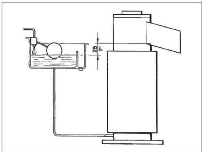
1 To Raise or Lower the water level:
a Loosen and remove the screw securing the mounting bracket of the water reservoir to the unit cabinet and raise the water reservoir to the correct level.
b Thread the mounting screw in the corresponding hole and tighten it.
2 For the reduction the water level as given above, and lower the bath, as soon as it is released from the casing.
WARNING. Be sure the electrical power supply circuit breaker and the inlet water supply are OFF, before starting any of the following Removal and Replacement procedures as a precaution to prevent possible personal injury or damage to the equipments.
B. Replacement of the gearmotor magnetic sensor
1 On F80, F120 remove the front/top and side/rear panels top and left side panels.
2. Unloose the three screws securing the plastic cover to the top of the gear motor and remove it.
3. Unloose the two screws securing the magnetic sensor to the plastic housing and withdraw it from its seat.
4. Trace the gear motor magnetic sensor terminal plug on the rear side of the control box (red with four terminal pins) and draw it out from its socket by carefully slackening the fastening tie.
5. To install the replacement gear motor magnetic sensor follow the above steps in reverse.
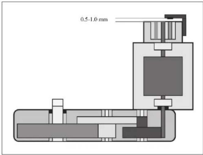
C Replacement of the auger, water seal, bearings and coupling
1 Remove the panels.
2 Follow the steps at item H to remove the ice spout.
3 On model F120 unloose and remove two screws and washers holding tight the spout bracket to the freezing cylinder.
4 On model F120 grasp the wire cap hook at the top of the freezer and pull out the auger, attached cap and icebreaker from the top of the freezer.
NOTE. If the auger cannot be pulled out, proceed to steps 10 and 11 of this paragraph, to gain access to the auger bottom. Then, with a rowhide mallet or placing a piece of wood on the bottom end of the auger, tap this bottom to break loose the auger and be able then to pull it out as per step 4 above.
D Replacement of the gear motor assay
1 Remove the front/top and side/rear panels.
2 Remove the three/four bolts and washers securingthegear reducerbase to theunitchassis, then remove bolts and lockwasherswhich attach the bottom of the aluminium adaptor to the gear reducer case cover.
3 Follow the steps of item E to remove the gear motor magnetic sensor.
4 Trace and disconnect the electric wires leads of the drive motor. Lift and remove the entire gear motor assembly.
E Change of the water level sensors in the bath
1 Remove the upper plate
2 Loosen the fastening nuts of the ring cable lugs of both the rod made of stainless steel - water sensors -, which are found on the cover of the swimming pool
3 Search for the terminal of the lowest water sensor with two red mandrels in the back part of the switch box and pull them out of their position by pressing on the fastening strap.
4 Proceed with the installation of the new lowest sensor in the reverse order.
F Change of the control card
1 Remove the front upper plate
2 Search for the terminal of the single sensor with two red mandrels in the back part of the switch box and pull them out of their position through pressing on the fastening strap.
3 Pull off the terminals for the electrical connections of the back part of the control card and then remove the whole control card by loosening the four screws, with which it is fastened in the electrical switch box made of plastic
4 Proceed with the installation of the new lowest sensor in the reverse order
G Change of the ice discharge opening
1 Loosen the screws and remove the upper plate.
2 Remove the wing nuts and the take the opening from the ice removal canal. Work on the optical reading device, so that these are not damaged.
3 The two shells, with which the polystyrene bowls in the upper part of the evaporators are fastened, and remove both the insulating bowls.
4 Pull out the opening made of stainless steel from its upper bronze part with the F 125 models, for the other models loosen both bolts, with which they are fastened in the icebreaker.
5 For Model F125 loosen both bolts, with which the bronze opening is fastened to the evaporator and free it.
NOTE. In F 125 and F 80 models inspect the rectangular rubber seal of the nozzle and, if damaged, replace it.
6 Proceed with the installation of the new opening in the reverse order.
H Replacement of the screw, seal ring, bearings and coupling
1 Loosen the screws and remove the front upper plate.
2 Change the procedure described in Point H for the removal of the ice discharge opening
3 Loosen and remove both screws, which are used to fasten the clip of the opening on the evaporator.
4 Grasp the ring in the upper part of the icebreakers of the evaporators and pull upwards hard to remove the unit icebreaker
NOTE. If you are unable to remove the auger assembly / icebreaker from above, switch to perform as described in paragraphs 10 and 11 of this paragraph in order to act on the bottom of the cochlea. Using a mallet of wood or plastic, beat on the lower end of the auger in order to loosen and eject it from the top of the evaporator.
5 For the F125 Model, remove the ring which is used to fasten the cover on the icebreaker, with the Seeger tongs. For the other models, a screw driver is used for removing the cover.
6 Loosen and remove the head bolt used to fasten the unit icebreaker storage on the screw (augur) and pull out the icebreaker unit from the screw.
7 Remove the remaining grease from the icebreaker unit and examine and change the OR seal, in case it is not alright.
8 Test the storage in the icebreaker carefully. Immediately change if there are signs of the start of wear and tear or lacking grease.
WARNING. The upper bearing works in critical conditions as regards its lubrication because it will insert within the icebreaker where you normally form a considerable condensation. E 'exhaustive use of dietary fat and water-repellent in order to provide adequate lubrication to the upper bearing.
9 Pull the brass rotating ring of the seal system from the lower part of the screw.
For the F125 Model, pull the brass rotating ring of the seal system from the lower part of the screw, the remaining models of the steel ring must be pulled out with a spring.
NOTE. Whenever you disassemble the auger to make a few checks or replacement, take care not to let dirt inside the evaporator and especially that these should not be deposited on the surface in graphite seal ring.
If there were any doubts, proceed without delay to the complete replacement of the seal ring.
10 Loosen and remove the three/four bolts, which are used to fasten the aluminum container underneath the evaporator.
11 Lift the evaporator and raise it from its container. After that push a wooden or plastic tool with a suitable knife and length in the upper part of the evaporator, so that it can be pressed out from the lower end. It is necessary in case a wooden hammer is used.
12 Press and remove the Super Flakes Ice Model with the sheets, from two screws pulled from the lower edge of the brass rings of the lower storage casing.
NOTE. Is a good practice to replace both the ring of the mechanical seal that the bearings, upper and lower, as well as O -rings each time it is disassembled the evaporator assembly. For this purpose there is a kit of these parties also accompanied by a tube of grease food and water repellent.
13 Pull the components of the drive coupling from aluminum container out.
14 Control the state of both half couplings. Immediately exchange if there is wear and tear.
15 Install the lower storage in its bronze casing and put it in such a way that the white plastic ring shows on the top.
16Install the upper storage of the icebreakers. The flat part starts with the radial part. The surfaces must be mounted upward.
17 Lubricant (grease) on the upper part. Then mount the roll cage with the smaller openings at the top, to allow a little movement between the plastic cage and the flat surfaces of the lower storage part (see diagram).
18 Grease and then mount the equalizing disc made of steel
19 After changing the O-Ring seal in the icebreaker, install the icebreaker on top of the screw and fasten it with the upper bolt.
20 Install the screw icebreaker unit in the evaporator. Use the previous points in a reverse order.
I Change of the gear motor
1 For the F125 Model the front/upper and the side/back plate
2 Loosen the three-four screws, which are used to fasten the evaporator on the upper casing.
3 Remove the sensors for the engine rotating direction according to the instructions in Point B. Loosen the screws which are used to fasten the gear motor on the framework.
4. Interruption of the supply of power of the motor through the electrical equipment. The gear motor is now released and can be exre-verse
5 To install the new gear motor, use the process in the reverse order.
J Change of the ventilator
1 For the F125 Model the front/upper and the side/back plate
2 Loosen the nuts and search and pull out the yellow/green grounding cable. The mandrel for the connection of the electrical cable of the ventilator.
3 For the F 125 Model, loosen the bolts which are used to fasten and take out the ventilator unit on the base of the device.
NOTE. When installing a new fan motor check that the blades do not touch anything and turn freely.
K Change of the driers
1 For the F 125 Model front/upper and the side/back plate
2 Remove the cooling agent from the system and let it flow into a particular container, which can be later recycled after a corresponding cleaning.
3 The cooling agents guides from both ends (for the F 125 Model, weld the capillary tube on a side of the drier).
4 Remove the seals to both ends for the mounting of the new driers and wearing the pipes of the cooling agent.
5 Carefully rinse the cooling agent circulation for humidity and remove the non-condensable gases after installing the new driers.
6 Fill the cooling agent circulation with the right amount of cooling agent (see type) and examine, whether appearances with the level smelted places are available.
7 Mount the previously removed plate again.
L Change of the evaporator
- Follow the instructions of Point H for the removal of the ice discharge opening.
2 Remove the shell of the connection of the water entry in the evaporator and draw out the pipe. Empty the water found in a container.
3 Pull out the sensor pipe of the evaporator as in Point B.
4 Remove the cooling agent from the system and let it run into a particular container, so that it can be recycled later after a corresponding cleaning.
5 Welding and separate the capillary tube and the collection/sucking unit from the outflow pipe of the evaporator.
6 Loosen the three-four bolts, which are used to fasten the evaporator on the upper casing of the gear motor.
7 Remove the evaporator of the gear motor and if necessary, remove the aluminum container* by loosening the three-four bolts of the evaporator.
NOTE. Replace the dryer filter whenever the refrigerant circuit is opened. Do not apply the new filter dehumidifier until all repairs or replacements have been made.
8 For the installation of the new evaporator the process used in a reverse order.
NOTE. Carefully purged the refrigerant circuit to remove moisture and non-condensable gases after the replacement of the evaporator.
M Change of the air-cooled condenser
5 For the F 125 Model the front/upper and the side/back plate
2 Remove the sensor pipe from the cooling bulb of the condensers.
3 Loosen the bolts, which are used to fasten it on the base/frame.
4 Remove the cooling agent from the system and let it flow into a particular container, to be able to recycle it later after the corresponding cleaning.
5 Weld the cooling agent pipes from both ends.
NOTE. Replace the dryer filter whenever the refrigerant circuit is opened. Do not apply the new filter dehumidifier until all repairs or replacements have been made.
6 For the installation of the new condensers, use the process in a reverse order
NOTE. Carefully purged the refrigerant circuit to remove moisture and non-condensable gases after the replacement of the condenser.
N Change of the water-cooled condensers
1 For the F 125 Model the front/upper and the side/back plate
2 Remove the sensing probe from the condenser.
3 Loosen and remove the bolts with which it is fastened on the base.
4 Unscrew the pipe terminal and pull the plastic pipe of the two ends of the condensers.
5 Remove the cooling agent from the system and let it flow into a particular container, to be able to recycle it later after the corresponding cleaning.
6 Welding the cooling agent pipes from the two ends of the condenser.
NOTE. Replace the dryer filter whenever the refrigerant circuit is opened. Do not apply the new filter dehumidifier until all repairs or replacements have been made.
7 For the installation of the new condensers use the process in reverse order.
NOTE. Carefully purged the refrigerant circuit to remove moisture and non-condensable gases after the replacement of the condenser.
O Exchange of the regulating valve (water-cooled equipment)
1 For the F 125 Model the front/upper and the side/back plate
2 Close the water stop valve and the supply pipes for the regulating valve from the back part of the device.
3 Loosen the pipe terminal and remove the plastic pipe from the pipe holder at the exit of the regulating valve.
4 Loosen the nuts, which are used for fastening the regulating valve in the frame of the equipment.
5 Remove the cooling agent from the system and let it flow in a particular container, to be able to recycle it later after the corresponding cleaning
6 Try the capillary tube of the regulating valve and weld it onto the cold circulation. Then remove it from the device.
NOTE. Replace the dryer filter whenever the refrigerant circuit is opened. Do not apply the new filter dehumidifier until all repairs or replacements have been made.
7 For the installation of the new condensers use the process in reverse order.
NOTE. Carefully purged the refrigerant circuit to remove moisture and non-condensable gases after the replacement of the condenser.
NOTE. The water flow passing through the pressure valve must be adjusted using the screw in the upper part of its stem until you have a condensing pressure of 14 bar.
P Change of the compressor
1 For the F 125 Model the front/upper and the side/back plate
2 Remove the cover and pull out the electrical cable from the terminals of the compressor.
3 Remove the cooling agent from the system and let it flow into a particular container, to be able to recycle it later after the corresponding cleaning
4 Weld the conveyor pipe as well as the suction pipe of the compressor.
5 Loosen the screws, which is used to fasten it to the base, and remove the compressor from the socket of the equipment.
6 For the F125 Model, weld the working/filling pipe, to be able to weld it on the new compressor.
NOTE. Replace the dryer filter whenever the refrigerant circuit is opened. Do not apply the new filter dehumidifier until all repairs or replacements have been made.
7 For the installation of the new compressors, use the process in a reverse order
NOTE. Carefully purged the refrigerant circuit to remove moisture and non-condensable gases after the replacement of the condenser.
AIR AND WATER COOLED
220-240/50/1
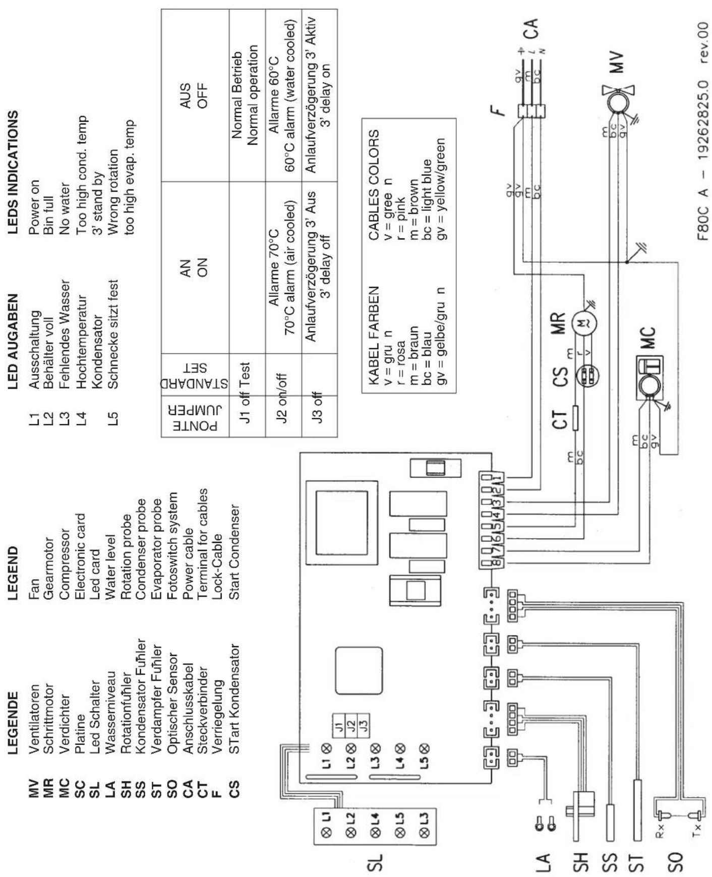
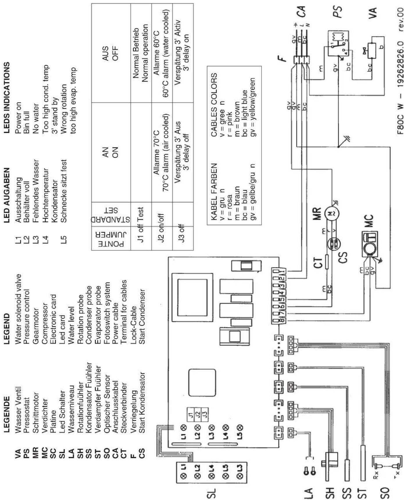
WIRING DIAGRAM F125
AIR AND WATER COOLED
220-240/50/1
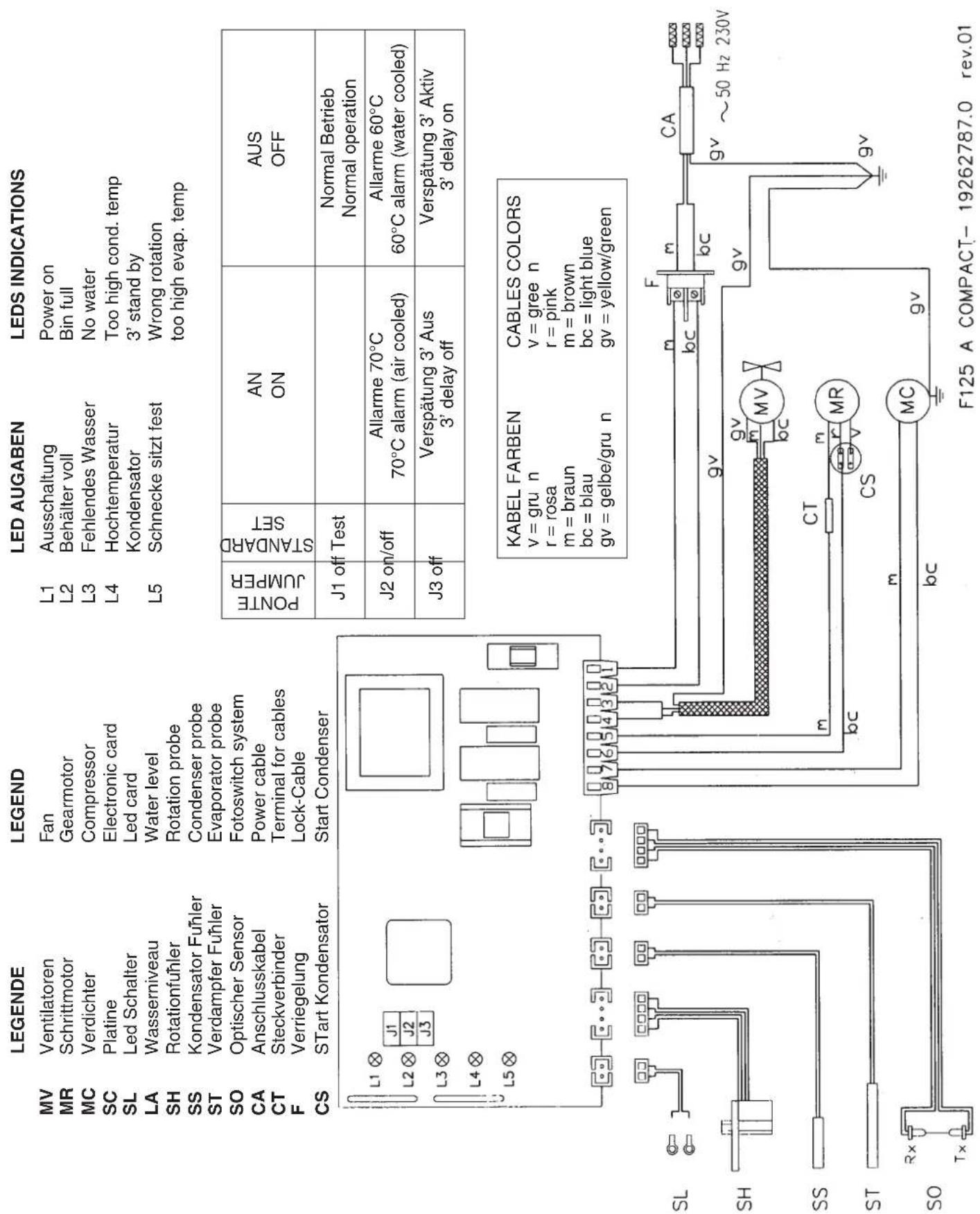
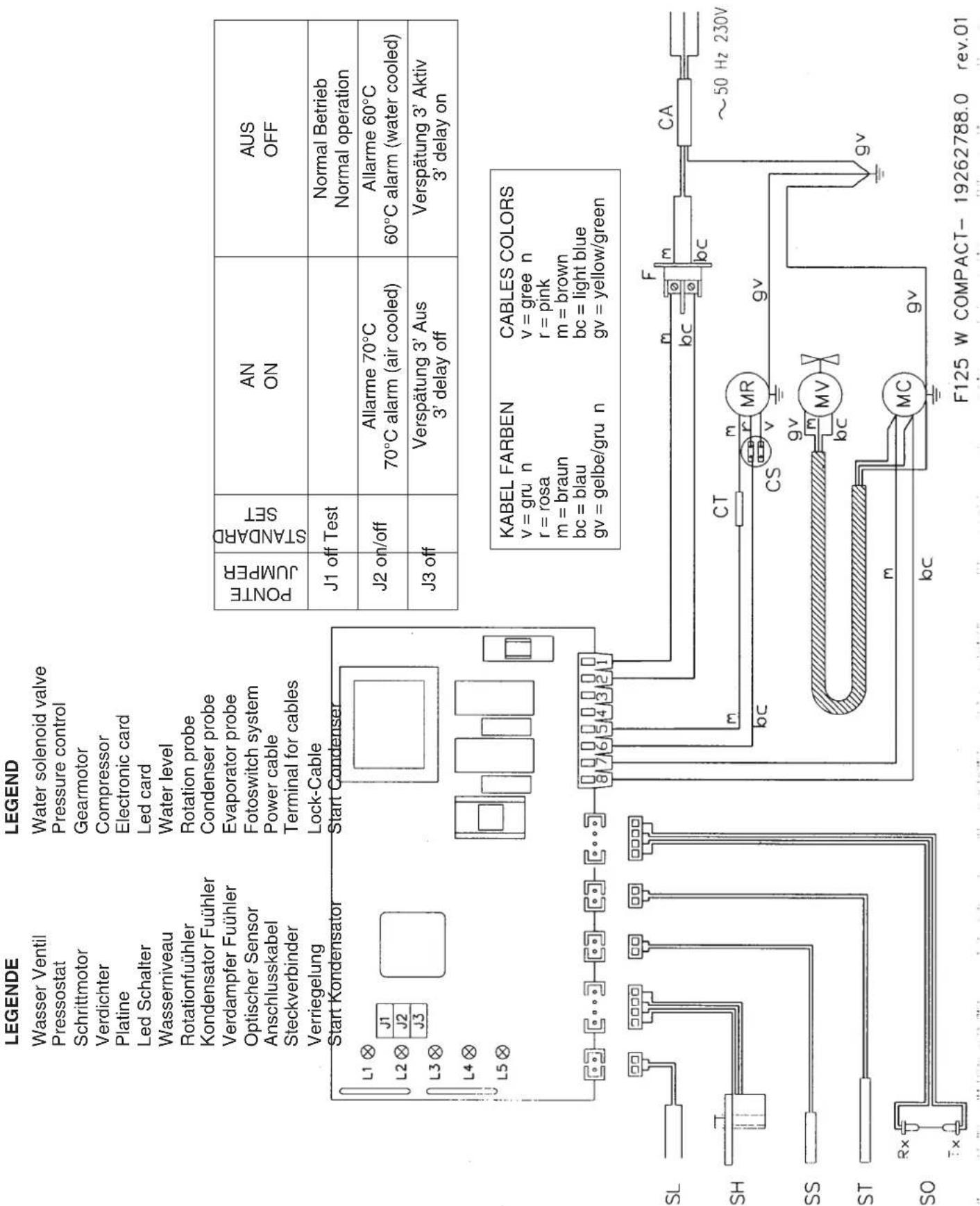
WIRING DIAGRAM F125
AIR AND WATER COOLED
220-240/50/1
| SYMPTON POSSIBLE CAUSE SUGGESTED CORRECTION | ||
| Unit will not runNo LED lighted-on | Blown fuse in P.C. Board | Replace fuse & check for cause of blown fuse |
| Master switch in OFF positionInoperative P.C. Board | Turn switch to ON positionReplace P.C. Board | |
| Loose electrical connections | Check wiring | |
| Inoperative or dirty ice level control | Replace or clean ice level control | |
| Bin full yellow LED glows with no ice in the bin | Shortage of water | See remedies for shortage of water. |
| No water yellow LED glows | Water too soft | Install a mineral salt metering device |
| Red-alarm LED glows | High head pressure | Dirty condenser. Clean |
| Ambient temperature too low | INOPERATIVE fan motor. Replace | |
| Red-alarm LED blinks | 3' stand by | Move unit in warmer location |
| Reverse rotation yellow LED blinks | Too hi evap. temperature | None - Wait the elapsed of 3' |
| Shortage or lack of refrigerant | Check and charge refrigerant system | |
| Inoperative evaporator sensor | Replace | |
| Reverse rotation yellow LED glows | Gear motor turns on reverse | Check stator winding and capacitor |
| Too low gear motor rotating speed | Check rotor bearings, freezer bearings and interior of freezer for scores. | |
| Drive motor doesn't turn | Replace whatever worn or damaged. | |
| Magnetic cylinder loose its magnetic charge | Check for power, open circuit, etc. | |
| Inoperative Condenser Sensor | Replace magnetic cylinder. | |
| Water yellow LED and red LED ON (steady) together | Inoperative Condenser Sensor | Replace it. |
| Inoperative Evaporator Sensor | Replace it. | |
| Compressor cycles intermittently | Low voltage | Check circuit for overloading |
| Non-condensable gas in system | Check voltage at the supply to the building. If low, contact the power company | |
| Compressor starting device with loose wires | Purge the system | |
| Check for loose wires in starting device | ||
| Low ice production Capillary tube partially restrictedMoisture in the systemLow water level in the freezer | Blow charge, add new gas & drier, after evacuating system with vacuum pumpSame as aboveAdjust to approx 20 mm below ice spoutCheck for leaks & rechargeClean or replace auger | |
| Shortage of refrigerant | ||
| Pitted or stained auger surface | ||
| SYMPTOM | POSSIBLE CAUSE SUGGESTED CORRECTION | |
| Wet ice Ambient temperature | too highUnder or overcharge of refrigerantHigh water level in the freezerFaulty compressorWorn out of the auger | Move unit to cooler locationRecharge with correct quantityLower to approx. 20 mm below ice spoutReplaceReplace |
| Machine runs but makes no ice | Water not entering in the freezerDrive motor or gear strippedMoisture in the system | Air look in feed line to freezer. Vent it Clogged feed line to freezer. Clean it Check repair or replacePurge, replace drier and re-charge |
| Water leaks Water seal leaking | Water feed line to freezer leakingFloat valve not closingSpout leaking | Replace water sealCheck and fasten hose clampCheck and adjust float valve setting screwTighten screws holding the spout |
| Excessive noise or chattering | Mineral or scale deposit on auger and inner freezer wallsLow suction pressureWater feed line to freezer cloggedLow water level into freezerWorn freezer bearings | Remove and manually polish auger and inner walls of freezer barrel using emery paperAdd refrigerant to rise suction pressureVent and clean itAdjust to approx. 20 mm below ice spout Check and replace |
| Gear motor noise Worn rotor | bearingsShortage or poor lubricant in gear caseGear case bearings and racers worn out | Check and replaceCheck for proper lubr. opening gear case. Top of gears must be covered with lubr.Check and replace worn parts |
| Shortage of water Strainer at water inlet fitting cloggedFloat reservoir water nozzle clogged-up | water inlet fitting cloggedFloat reservoir water nozzle clogged-up | Remove strainer and cleanRemove float valve and clean nozzle |
MAINTENANCE AND CLEANING INSTRUCTIONS
A GENERAL
The periods and the procedures for maintenance and cleaning are given as guides and are not to be construed as absolute or invariable. Cleaning, especially, will vary depending upon local water and ambient conditions and the ice volume produced; and, each icemaker must be maintained individually, in accordance with its particular location requirements.
B ICEMAKER
The following maintenance should be scheduled at least two times per year on these icemakers.
1 Check and clean the water line strainer.
2 Remove the cover from the float reservoir - care to do not damage the two water sensors - and depress the float to make sure that a full stream of water enters into the reservoir. If not gently remove the float valve from its reservoir bracket than clean the hole of the nozzle.
3 Check that the icemaker is levelled in side to side and in front to rear directions.
4 Check that the water level in the water reservoir is below the overflow but high enough that it does not run out of the spout opening.
5 Clean the water system, water reservoir and the interior of freezing cylinder using a solution of cleaner.
Refer to procedure C cleaning instructions and after cleaning will indicate frequency and procedure to be followed in local areas.
NOTE. Cleaning requirements vary according to the local water conditions and individual user operation.
6 If required, polish the two sensor rods secured to the float reservoir cover, heavy scale sediment on them can be removed with the help of a bit of cleaner.
7 With the ice machine and fan motor OFF on air cooled models, clean condenser using vacuum cleaner, whisk broom or non metallic brush taking care to do not damage the condenser/ambient temperature sensor.
8 Check for water leaks and tighten drain line connections. Pour water down bin drain line to be sure that drain line is open and clear.
9 Check the ice level control sensor to test shut-off. Close the bottom of the ice chute and wait till it is completely full of ice so to cut off the light beam for at least 6 seconds. This should cause the immediate blinking of the Bin Full YELLOW LED located in the front of P.C. Board and, 6 seconds later, the total stopping of the ice maker with the simultaneous light up of the same LED (steady).
Within few seconds from the removal of the ice between the sensor lights the ice maker resume its operation.
NOTE: The ice level control uses devices that sense light, therefore they must be kept clean enough so they can "see".
Everythree-monthsremovetheopticalsystem then clean/wipe the sensing "eyes" with a clean soft cloth.
10Check for refrigerant leaks and for proper frost line, which should frost as far as approx. 20~cm (8^ ) from the compressor.
11 When doubtful about refrigerant charge, install refrigerant gauges on corresponding service valvesandcheckforcorrect refrigerantpressures.
12Check that fan blades move freely and are not touching any surfaces.
13 Remove the retaining ring and the hook and cap from the top of the freezer assembly then inspect the top bearing, wipe clean of all grease and apply a coating of food grade water proof grease.
NOTE. It is recommended to use only food grade and waterproof grease to lubricate the freezer top bearing.
14Check the quality of ice.
NOTE. It is not abnormal for some water to emerge from the ice spout with the flaker ice.
Ice flakes should be wet when formed, but will cure rapidly to normal hardness in the bin.
C. CLEANING INSTRUCTIONS OF WATER SYSTEM
1 Switch OFF the Master disconnect switch on the power line.
2 Remove all ice stored in the bin to prevent it from getting contaminated with the cleaning solution.
3. Shut close the water shutoff valve on water line.
4 Remove the top panels to gain access to the water reservoir.
5. Remove the float reservoir cover and with a piece of copper wire short the two metal pins of the water level sensor.
NOTE. Put one or both of the water sensor on the casing of the equipment, because in this way through the condenser sensor voltage will be transferred and the equipment will be switched off through that due to high temperature.
6 Place a water pan under the freezer water inlet port, disconnect the water hose from this port and allow the water from the freezer to flow into the pan. Then refit the water hose to the freezer water inlet port.
7 Prepare the cleaning solution in a plastic container.r
8 Pour the cleaning solution into the water reservoir.
9 Wait till the machine starts to discharge ice, then continue to slowly pour the cleaning solution into the water reservoir taking care to maintain the level just below the overflow.
NOTE. The ice produced with the decalcification solution is yellowish and smooth. In this phase, there are loud noises from the freezer due to the rubbing between the rising ice and the evaporator walls. In this case, it is recommended that the equipment should be switched off for some minutes, so that the decalcification solution in the freezer can be released.
10 When all the cleaning solution has been used up, open the water shutoff valve to allow new fresh water to flow into the reservoir. Let the unit to continue to run until the ice resumes the normal colour and hardness.
11Stop the icemaker and pour warmwater on the ice deposited into the storage bin to melt it up.
ATTENTION use ice produced with the cleaner solution. Be sure none remains in the bin.
12Left the unit running for approx 10 minutes then remove the copper wire used to jump the two sensors for the water level and place back correctly the cover on the float reservoir.
Bartscher
Bartscher
PRODUCTeurs
ÉLECTRONIQUES
MODULAIRES
DE GLACE EN PÉPITES
104409F80
104436F125
MANUEL DE SERVICE
71503135-0-000 service Flakers FR
SOMMAIRE
RAFFR. AD ACQUA/WATER COOLED
WASSERGEKUHLT/REFR.A EAU
REFR.A AGUA
Temperatura acqua/Water temperature
Wassertemperature/Temperature eau Temperatureaigua
| ℃ | 32° | 21° | 15° | 10° | |
| 10° | 76 | 81 | 84 | 86 | kg |
| 21° | 72 | 77 | 80 | 82 | kg |
| 32° | 68 | 74 | 76 | 78 | kg |
| 38° | 64 | 70 | 71 | 72 | kg |
RAFFR. AD ARIA/AIR COOLED
LUFTGEKÜHLT/REFR. A AIR
REFR.AIRE
Temperatura acqua/Water temperature
Wassertemperature/temperature eau
Temperatura agua
| °C | 32° | 21° | 15° | 10° | |
| 10° | 78 | 84 | 87 | 90 | kg |
| 21° | 72 | 78 | 81 | 84 | kg |
| 32° | 58 | 63 | 66 | 68 | kg |
| 38° | 48 | 52 | 54 | 56 | kg |
RAFFR. AD ACQUA/WATER COOLED
WASSERGEKUHLT/REFR.A EAU
REFR.AAGUA
Temperatura acqua/Water temperature
RAFFR. AD ARIA/AIR COOLED
LUFTGEKUHLT/REFB.A AIR
REFR.AIRE
Temperatura acqua/Water temperature
Wassertemperatur/Temperature eau
Temperatura agua
| Temperatura ambiente |
| Ambientura |
| Raumtemperatur |
| Temperatura ambiente |
| Temperatura ambiente |
| °C | 32° | 21° | 15° | 10° | |
| 10° | 102 | 111 | 115 | 120 | kg |
| 21° | 95 | 104 | 108 | 110 | kg |
| 32° | 84 | 90 | 94 | 97 | kg |
| 38° | 75 | 81 | 85 | 87 | kg |
Prod.ghiaccio in 24 h/ice prod.per 24 h
Eisprod. in 24 h/Prod.de glace en 24 h
Prod. de hiefo en 24 h
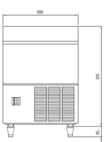
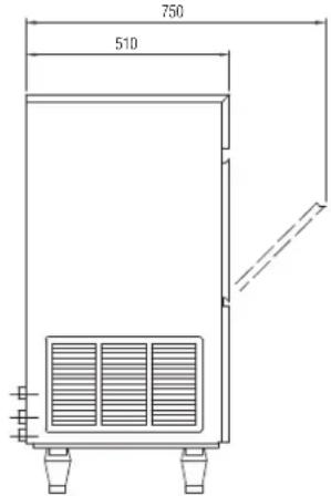
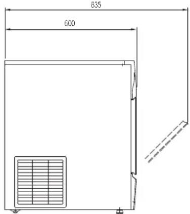
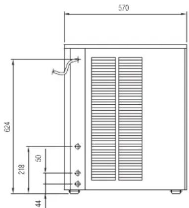
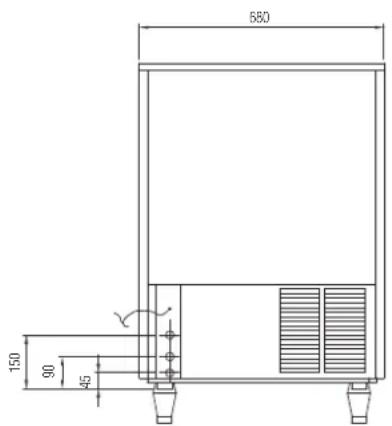
Dimensioni / Dimensions / Masse / Dimensions / Dimensiones
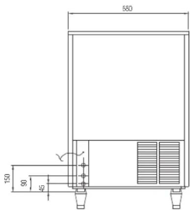
INFORMATIONS GÉNÉRALES ET INSTALLATION
A. Introduction
RAFFR. AD ACQUA/WATER COOLED
WASSERGEKUHLT/REFR.A EAU
REFR.AAGUA
Temperatura acqua/Water temperature
RAFFR. AD ARIA/AIR COOLED
LUFTGEKÜHLT/REFB.A AIR
REFR.AIRE
Temperatura acqua/Water temperature
Wassertemperature/Temperature eau
Temperatura agua
| Temperatura ambiente Ambient temperature Raumtemperatur Temperatura ambiente Temperatura ambiente | °C | 32° | 21° | 15° | 10° | |
| 10° | 78 | 84 | 87 | 90 | kg | |
| 21° | 72 | 78 | 81 | 84 | kg | |
| 32° | 58 | 63 | 66 | 68 | kg | |
| 38° | 48 | 52 | 54 | 56 | kg |
Prod.ghiaccio in 24 h/ice prod.per 24 h
Eisprod. in 24 h/Prod. de glace en 24 h
Prod.de hlelo en 24h
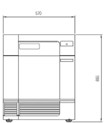
Dimensioni / Dimensions / Masse / Dimensions / Dimensiones
SPECIFICHE TECNICHE
FABBRICATORE ELETTRONICO MODULARE DI GHIACCIO GRANULARE mod. F 125 (R 134a)
| Produzione di gliaccio in 24 ore sono a Ice produced for 24 hours up to Eisproduktion in 24 Stunden bis zu Production de glace en 24 h jusqu'à Produzione de hielo en las 24 horas hasta | kg. 120 |
| Raffreddamento unità condensatrice arla o acqua: consumo n. 24 litri per ora* Condensing unit cooling air or water: consumption n. 24 litres per hour* Kondensatoreinheit Luft oder Wasser: Verbrauch n. 24 liter pro Stunde* Refroidissement de l'unité de condensation air ou eau: consommation n. 24 litres par heures* Refrigeración de launidad condensadora aire o agua: consumo n. 24 litros para hora* | |
| Potenza assorbita/Absorbed power/Leistungsaufnahme Pulsance absorbée/Potencia Absorbida | W 480 |
| Refrigerante/Refrigerant/Kältemittel Réfrigérant/Refrigerant | R 134a |
| Attacco entrata acqua/Water inlet connection Anschluss für Wasserzufluss/Prise entree d'eau/conexión entrada agua | 3/4" Gas |
| Attacco scarico acqua/Water output connection Anschluss für Wasserabfluss/Prise écoulement d'eau Conexión desague | mm. Ø 20 |
| Alimentazione monofase/Single phase input/ Einphasige Spannung/Alimentation monophase Alimentación monofásica | 220V-240V - 50 Hz |
| Alimentazione voltaggi speciali: a richiesta Extra voltages: on request Andere Spannungen: Lieferbar auf Wunsch Alimentation voltages specialaux: Otros voltajes especialies: | sur besoin según pedido |
| Capacità deposito - Storage bin capacity Inhalt des Vorrats-Eisbehänders Capacité de la réserve - Capacidad del deposito | kg. 27 |
| Carrozzerla External structure Ausbührnung Carrosserie Carroceria | inox |
| Peso netto/Net weight/Netto Gewicht Poids net/Peso neto | kg. 64 |
(°) con temperatura acqua 15 °C
with water temperature 15^
mit Wassertemperatur 15^
avec température eau 15 °C
con temperatura agua 15^
| °C | 32° | 21° | 15° | 10° |
| 10° | 97 | 108 | 117 | 120 |
| 21° | 95 | 105 | 115 | 117 |
| 32° | 90 | 100 | 107 | 110 |
| 38° | 87 | 97 | 102 | 105 |
| °C | 32° | 21° | 15° | 10° |
| 10° | 102 | 111 | 115 | 120 kg |
| 21° | 95 | 104 | 108 | 110 kg |
| 32° | 84 | 90 | 94 | 97 kg |
| 38° | 75 | 81 | 85 | 87 kg |
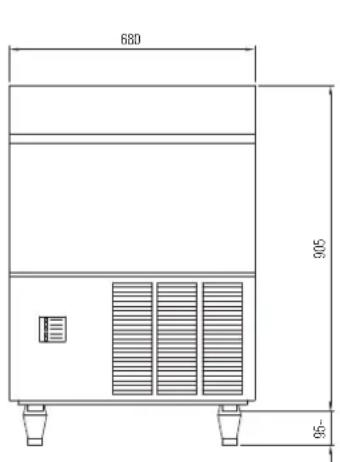
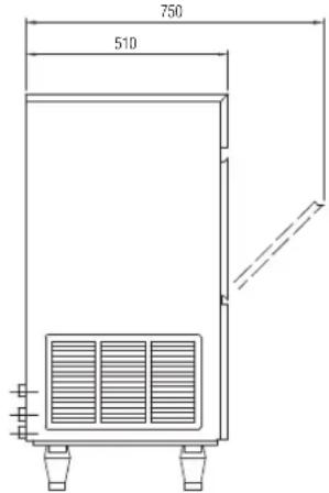
Dimensioni / Dimensions / Masse / Dimensions / Dimensiones
- GENERAL INFORMATION AND INSTALLATION
- OPERATING INSTRUCTIONS
- PRINCIPLE OF OPERATION (how it works)
- ADJUSTMENT, REMOVAL AND REPLACEMENT PROCEDURES
- MAINTENANCE AND CLEANING INSTRUCTIONS
- TECHNICAL SPECIFICATION
- ELECTRONIC MODULAR
- FLAKERS mod. F80 (R 134a)
- A INTRODUCTION
- UNPACKING AND INSPECTION Icemaker
- LOCATION AND LEVELLING
- ELECTRICAL CONNECTIONS
- WATER SUPPLY AND DRAIN CONNECTIONS
- WATER SUPPLY
- WATER SUPPLY - WATER COOLED MODELS
- WATER DRAIN
- WATER DRAIN - WATER COOLED MODELS
- FINAL CHECK LIST
- INSTALLATION PRACTICE
- STARTUP
- GEAR MOTOR/S
- COMPRESSOR
- REFRIGERANT CIRCUIT
- CLOGGED CONDenser (Air cooled version) INSUFFICIENT FLOW OF COOLING
- AMBIENT TEMPERATURE HIGHER THEN 43°C (110°F)
- MECHANICAL SYSTEM
- COMPONENTS DESCRIPTION
- A Evaporator temperature sensor
- B Water level sensor
- C Condenser temperature sensor
- D Electromagnetic sensor
- E Optical ice level control
- F P.C. BOARD (Data processor)
- GREENLED
- YELLOW LED
- REDLED
- YELLOW AND RED LED
- G Jumpers
- H Float reservoir
- Freezing cylinder or evaporator
- J Eisbrecher
- L Fan motor (Air cooled version)
- M Water regulating valve
- N Compressor
- A Adjustment of the evaporator water level
- Replacement of the gearmotor magnetic sensor
- C Replacement of the auger, water seal, bearings and coupling
- D Replacement of the gear motor assay
- E Change of the water level sensors in the bath
- F Change of the control card
- G Change of the ice discharge opening
- H Replacement of the screw, seal ring, bearings and coupling
- I Change of the gear motor
- J Change of the ventilator
- K Change of the driers
- L Change of the evaporator
- M Change of the air-cooled condenser
- N Change of the water-cooled condensers
- O Exchange of the regulating valve (water-cooled equipment)
- P Change of the compressor
- AIR AND WATER COOLED
- 220-240/50/1
- WIRING DIAGRAM F125
- A GENERAL
- B ICEMAKER
- CLEANING INSTRUCTIONS OF WATER SYSTEM
- ATTENTION use ice produced with the cleaner solution. Be sure none remains in the bin.
- Bartscher
- SOMMAIRE
- INFORMATIONS GÉNÉRALES ET INSTALLATION
- Introduction
- SPECIFICHE TECNICHE
- FABBRICATORE ELETTRONICO MODULARE DI GHIACCIO GRANULARE mod. F 125 (R 134a)
Brand : BARTSCHER
Model : F 125
Category : Ice machine