RVMTK330SS - Microwave Oven VIKING - Free user manual and instructions
Find the device manual for free RVMTK330SS VIKING in PDF.

| Product type | Built-in microwave oven |
| Brand | Viking |
| Model | RVMTK330SS (trim kit included) |
| Overall dimensions (W x H x D) | 24 in x 13-3/8 in x 19-1/8 in (609 x 339 x 487 mm) |
| Interior dimensions (W x H x D) | 17-3/8 in x 10-1/2 in x 18-5/8 in (441 x 266 x 473 mm) |
| Interior capacity | 2 ft³ (0.04 m³) |
| Net weight | 46 lb (20.9 kg) |
| Electrical rating | 120 V AC / 60 Hz |
| Maximum power | 1.5 kW (13 A) |
| Main function | Microwave cooking |
| Turntable | Yes (removable for installation) |
| Installation type | Built-in or under cabinet (trim kit supplied) |
| Door material | Glass and stainless steel |
| Certifications | FCC, DHHS (FDA), UL (U.S./Canada) |
| Cleaning | Wipe with a damp cloth and mild soap; do not use abrasive cleaners |
| Safety | Unplug before installation; do not remove warning labels |
| Spare parts | Trim kit including door frame, lower duct, fixing brackets, side trims |
| Repairability | Repair by qualified technician recommended; contact Viking at 1-888-845-4641 |
| Ambient operating temperature | Not specified (estimated: 5 °C to 35 °C) |
| Compatibility | For Viking microwave oven models RVM320 / CRVM320 |
Frequently Asked Questions - RVMTK330SS VIKING
User questions about RVMTK330SS VIKING
0 question about this device. Answer the ones you know or ask your own.
Ask a new question about this device
Download the instructions for your Microwave Oven in PDF format for free! Find your manual RVMTK330SS - VIKING and take your electronic device back in hand. On this page are published all the documents necessary for the use of your device. RVMTK330SS by VIKING.
USER MANUAL RVMTK330SS VIKING
Microwave Built-In Trim Kit
Table of Contents
Warnings & Important Information 2
Specifications 3
General Information 4
Parts Included in the Kit 4
Cabinet or Wall Cutout 4
Electrical Outlet Location 4
Installation 5
Mounting Template 5
Bottom Duct Assembly 6
Mounting Bracket Assembly 6
Cabinet Installation 7
Frame Assembly 7
Side Decoration Assembly (For Surface Mount Only) 8
Over Oven Installation 8
Performance Checklist 8
IMPORTANT—Please Read and Follow!
- Before beginning, please read these instructions completely and carefully.
- Be sure to DISCONNECT THE PLUG of the microwave oven from the electrical outlet before installing the built-in trim kit. Remove the turntable from the oven cavity.
- Because the kit includes metal parts, caution should be used in handling and installation to avoid the possibility of injury.
- Do not remove permanently affixed labels, warnings, or plates from the product. This may void the warranty.
- Please observe all local and national codes and ordinances.
- The installer should leave these instructions with the consumer who should retain for local inspector's use and for future reference.
WARNING
This built-in trim kit is designed for use only with microwave ovens specifying built-in trim kit RDMTK302 on the rating label on the left side wall of the oven cavity.
Specifications
| Microwave Oven Built-In Trim Kit | |||
| RVM320 / CRVM320 RVMTK330 | |||
| Overall Width | 24" (60.9 cm) | 29-1/2" (74.9 cm) | |
| Overall Height from Bottom | 13-3/8" (33.9 cm) | 17-1/4" (43.7 cm) | |
| Overall Depth from Rear | 19-1/8" (48.7 cm) | NA | |
| Oven Interior | Width 17-3/8" (44.1 cm)Height 10-1/2" (26.6 cm)Depth 18-5/8" (47.3 cm)Overall 2.0 cu. ft. | NA | |
| Electrical Requirements | 120VAC/60 Hz | NA | |
| Max. Amp Usage | 1.5 KW 13 amps | NA | |
| Approx. Shipping Wt. | 46 lbs. (20.9 kg) | 15 lbs. (6.9 kg) | |
In compliance with standards set by:
FCC – Federal Communications Commission Authorized.
DHHS – Complies with Department of Health and Human Services (DHHS) rule, CFR, Title 21, Chapter I, Subchapter J.

- This symbol on the Rating label means the product is listed by Underwriters Laboratories, Inc. for use in USA or Canada.
General Information
Parts Included in the Kit
| Item Part Name QTY | ||
| 1 | Frame Assembly 1 | |
| 2 | Bottom Duct 1 | |
| 3 | Mounting Bracket 2 | |
| 4 | Screw A :1-3/16" length 2 | |
| 5 | Screw B: 1-3/4" length 4 | |
| 6 | Side Decoration (Surface Mount Only) | 2 |
| 7 | Surface Mounting Template 1 | |
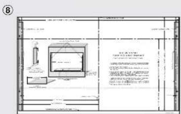
| 8 | Flush Mounting Template | 1 |

natural_image
Technical line drawing of a rectangular frame with side supports and two parallel cylindrical components (no text or symbols)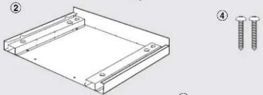
natural_image
Technical drawing of a rectangular frame with two screws, shown with numbered annotations (no text or symbols present)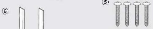
natural_image
Illustration of two screw sets and four screws, no text or symbols present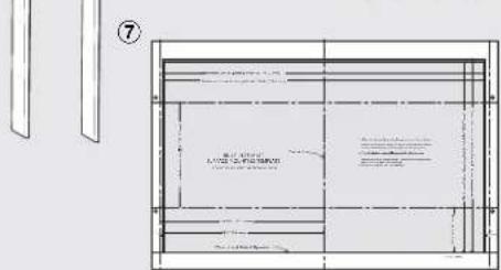
Cabinet or Wall Cutout
| Cutout Dimensions | Flush Mount | Surface Mount | |
| Height Ⓐ | Minimum | 17-5/16" (439.8mm) | 16-9/16" (420.7mm) |
| Maximum | N/A | 16-13/16" (427mm) | |
| Width Ⓑ | Minimum | 29-5/8" (752.5mm) | 27-3/4" (704.9mm) |
| Maximum | N/A | 28" (711.2mm) | |
| Depth Ⓒ | Minimum | 20" (503mm) | 20" (503mm) |

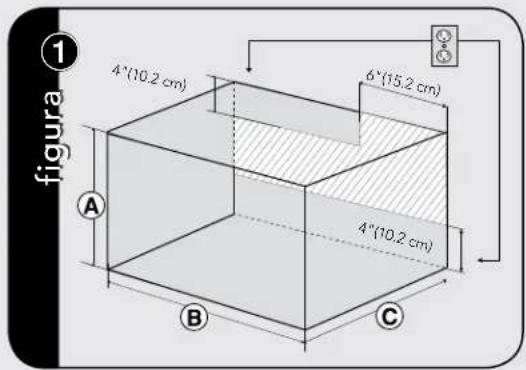
Electrical Outlet Location
! CAUTION
Outlet should NOT be in the shaded area as indicated on figure ①.
NOTES:
- If the Depth (C) dimension is greater than 21" (53.3 cm), the outlet location may be in any area on the rear wall.
- The floor of the opening should be constructed of plywood strong enough to support the weight of the oven and floor load (approximately 100 pounds). The floor should be level for proper operation of the oven. Be sure to check the local building code as it may require that the opening be enclosed with side, ceiling and rear partition. The proper functioning of the oven does not require the enclosure.
Installation
Mounting Template
Determine which mounting method to use based on the required configuration. See figure ②A for FLUSH MOUNT and ②B for SURFACE MOUNT.
Align the template corresponding to the required mounting method to the center of the cabinet. Make sure that the template is level with the floor. Tape it into place. Cut the cabinet opening along the lines specified on the template. Leave template taped in place.
figure ②
A FluSh MounT ConFIGuRATlon—Microwave Oven and Frame Assembly glass are flush with the cabinet.
SuRFACE MounT ConFIGuRATlon
—Microwave Oven and Frame Assembly
protrude from the surface of the cabinet.
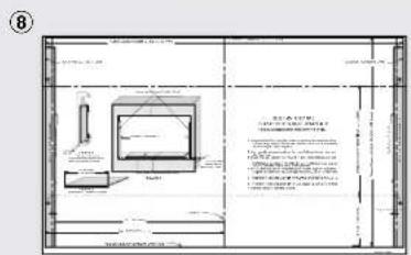
natural_image
3D line drawing of a rectangular box with internal compartments and a recessed panel (no text or symbols)For SURFACE MOUNT, predrill 4 holes marked "A" with a 1/16" drill bit. Remove template from the cabinet. Go to Bottom Duct Assembly.
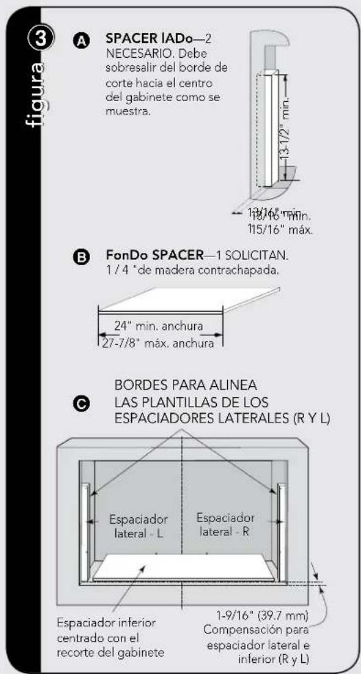
figure ③
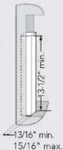
A SIDE SPACER—2
REQUIRED. Must
protrude from edge of
cabinet cutout towards
center as shown.
B BoTToM SPACER—1 REQUIRED. 1/4" plywood.
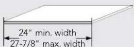
EDGES TO ALIGN SIDE SPACER
TEMPLATES (R and L)
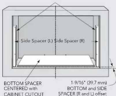
For FLUSH MOUNT, two (2) side spacers and one (1) bottom spacer are required. Spacers are not included in the kit and must be fabricated by installer. See figures 3A and B for spacer requirements. Make sure that all three spacers are offset from the front of the cabinet by 1-9/16".
Cut out the Side Spacer Templates (R and L) from the Flush Mounting Template. Align the indicated edges to the corresponding right and left side spacers as shown in figure ③. Make sure to align the bottom edges of the side spacer templates to the floor of the cabinet opening. Predrill two (2) holes marked "A" on Side Spacer Template – R and two (2) holes marked "B" on Side Spacer Template – L with 1/16" drill bit.
Remove templates from the cabinet.
Installation
Bottom Duct Assembly
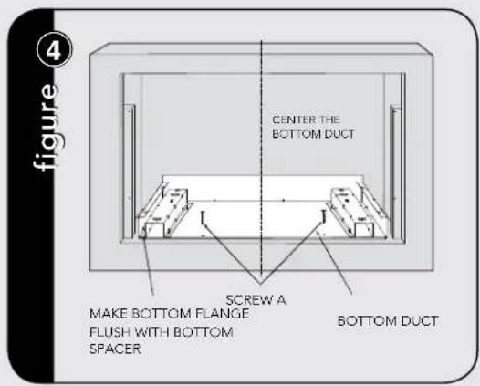
Place the Bottom Duct in the cabinet opening. For FLUSH MOUNT, it will rest on the bottom spacer centered with the cabinet. See figure 4.
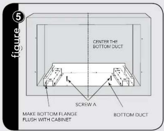
For SURFACE MOUNT, the Bottom Duct will rest on the floor of the opening. See figure 5.
Align the Bottom Duct to the center of the opening with the bottom flange securely flush with the bottom spacer (for FLUSH MOUNT) or the cabinet (for SURFACE MOUNT).
Secure the Bottom Duct Assembly with the two (2) SCREWS A. See figures ④ and ⑤ respectively.
Mounting Bracket Assembly
Position the mounting brackets to align with the predrilled holes that were drilled with the mounting template.
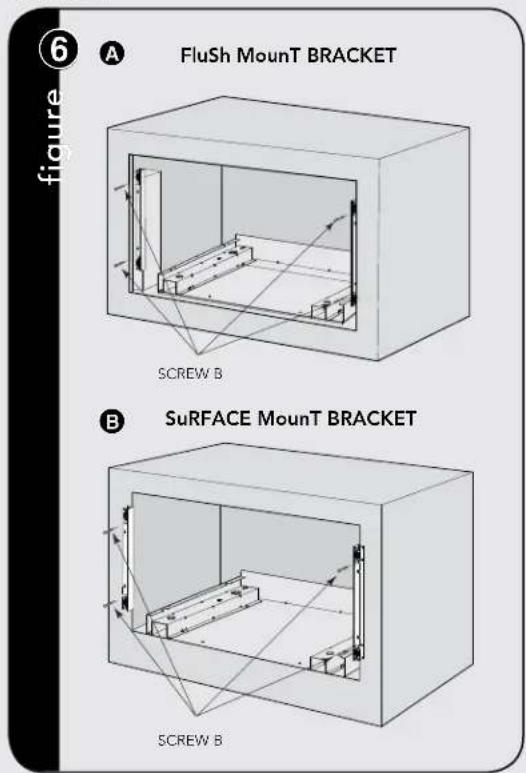
The enclosed ends of the mounting brackets should face inwards. Check that they are vertical and then secure loosely with four (4) Screws B. See figure 6.

Installation
Align the mounting brackets horizontally by sliding them back and forth along the screw slots until the brackets are exactly 27-1/2" apart and equal distance from the cabinet sides. See figure 7.
Once the brackets are correctly positioned, securely tighten the four (4) screws B.
Cabinet Installation
Place the oven adjacent to the wall or cabinet opening. Plug the power cord into the electrical outlet.
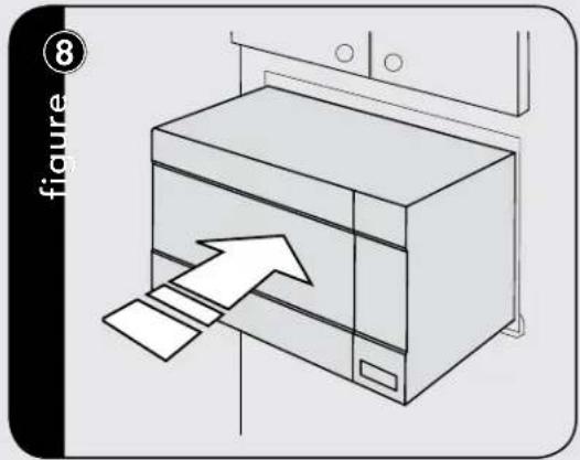
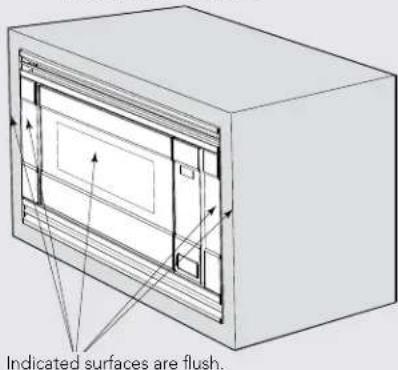
Carefully guide the assembled oven into the prepared opening. Slide the oven onto the Bottom Duct Assembly. See figure 8.
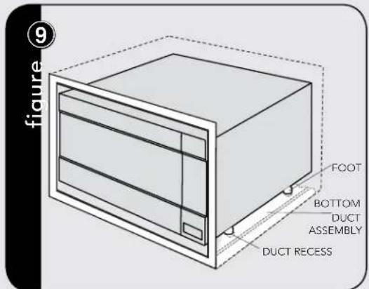
Avoid pinching the cord between the oven and the wall. Adjust the position of the oven so that the feet of the oven are fitted into the recesses of the Bottom Duct Assembly. See figure 9.
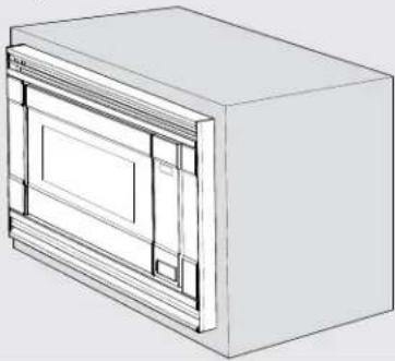
Frame Assembly
Turn over FRAME ASSEMBLY to locate the 4 ball studs.
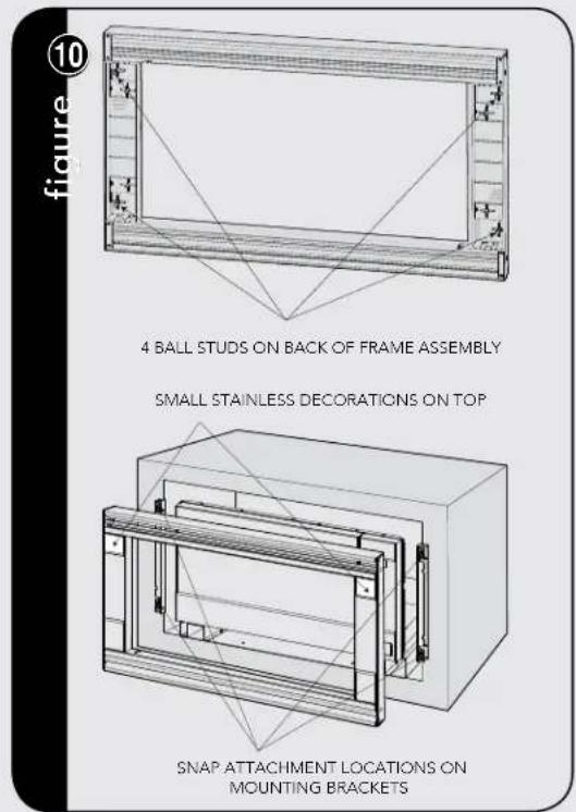
Position the FRAME ASSEMBLY with the small stainless decorations on top. Align the 4 ball studs with the 4 snap attachments at both ends of the MOUNTING BRACKETS.
Secure the FRAME ASSEMBLY by firmly pushing it onto the Mounting Brackets engaging the four (4) snap attachments. See figure 10.
Installation
Side Decoration Assembly (For Surface Mount Only)
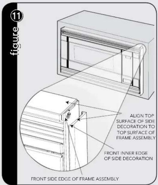
Peel the backing off the tape on the backside of the SIDE DECORATIONS. Align the front inner edge of the side decorations to the front side edge of the FRAME ASSEMBLY.
Align the top surface of the side decorations to the top surface of the FRAME ASSEMBLY. Secure the side decorations by pressing them firmly against the side of the FRAME ASSEMBLY. See figure 11.
Over Oven Installation
Performance Checklist
- Make sure the unit has been installed according to all of the Installation Instructions and the required Mounting Template.
- Plug in the power cord.
- Keep the Use & Care Manual and Installation Manual.
Viking Range, LLC
111 Front Street
Greenwood, Mississippi 38930 USA
(662) 455-1200
For product information
call 1-888-845-4641


natural_image
Technical line drawing of a rectangular frame with ribbed sides and two parallel cylindrical components (no text or symbols)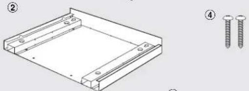
natural_image
Technical line drawing of a rectangular metal frame with two screws, shown with numbered annotations (no text or symbols on the diagram itself)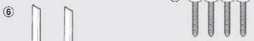
natural_image
Simple line drawing of two vertical panels and three threaded rods (no text or symbols)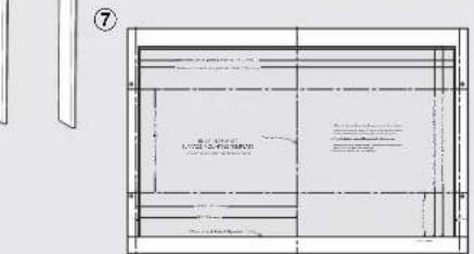
natural_image
Technical line drawing of a rectangular cabinet or enclosure with internal compartments and directional arrows indicating flow or movement (no text or symbols present)natural_image
3D line drawing of a rectangular cabinet or enclosure with internal compartments and ventilation grilles (no text or symbols)natural_image
Line drawing of a cabinet with an arrow pointing to a paper sheet, no text or symbols presentnatural_image
Technical line drawings of a rectangular frame with internal ventilation grilles and two separate cylindrical components (no text or symbols)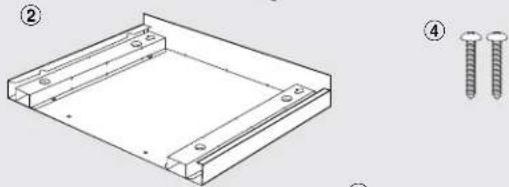
natural_image
Technical line drawing of a rectangular frame with two screws, shown with numbered annotations (no text or symbols on the diagram itself)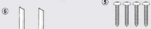
natural_image
Illustration of two screw sets and five threaded fasteners (no text or symbols)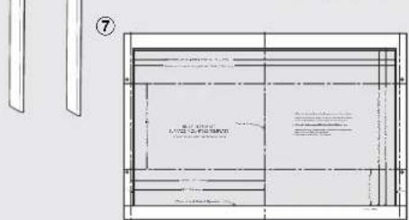

Abertura del gabinete o pared
| Dimensiones de recorte | Brindas Montaje | Superficie Montaje | |
| Altura A | Mínimo | 17-5/16" (439.8mm) | 16-9/16" (420.7mm) |
| Máximo | N/A | 16-13/16" (427mm) | |
| Ancho B | Mínimo | 29-5/8" (752.5mm) | 27-3/4" (704.9mm) |
| Máximo | N/A | 28" (711.2mm) | |
| Profundidad C | Mínimo | 20" (503mm) | 20" (503mm) |
For SURFACE MOUNT, predrill 4 holes marked "A" with a 1/16" drill bit. Remove template from the cabinet. Go to Bottom Duct Assembly.