
LNZ3522B - Surveillance Camera Lorex - Free user manual and instructions
Find the device manual for free LNZ3522B Lorex in PDF.

| Product Type | Surveillance Camera |
| Brand | Lorex |
| Model | LNZ3522B |
| Resolution | 1080p (2.1 MP) |
| Sensor | 1/3" 2.1 MP |
| Lens | 3.6 mm, F1.2, fixed |
| Horizontal Field of View | 90° |
| Pan / Tilt | ±180° / 90° |
| Pan/Tilt Speed (Preset) | Up to 100°/s |
| Digital Zoom | 3x |
| Minimum Illumination | 0.1 lux (black and white) |
| Video Format | NTSC / PAL |
| Connectivity | RJ45 10/100M Ethernet (PoE) |
| Power Supply | PoE (Class 3) or 12 V DC (adapter not included) |
| Power Consumption | Max 220 mA |
| Operating Temperature | -20°C to 60°C |
| Ingress Protection | IP66 (indoor/outdoor) |
| Weight | 0.25 kg (0.55 lb) |
| Dimensions | Diameter 13 cm, height 5 cm |
| Presets | 25 positions |
| Built-in Microphone | Yes |
| NVR Compatibility | Lorex LNR100 and LNR400 series only |
| Night Vision | Requires ambient light (no IR LEDs) |
| Cleaning | Damp cloth only, no chemicals |
| Safety | Do not open, refer to qualified technician |
Frequently Asked Questions - LNZ3522B Lorex
User questions about LNZ3522B Lorex
0 question about this device. Answer the ones you know or ask your own.
Ask a new question about this device
Download the instructions for your Surveillance Camera in PDF format for free! Find your manual LNZ3522B - Lorex and take your electronic device back in hand. On this page are published all the documents necessary for the use of your device. LNZ3522B by Lorex.
USER MANUAL LNZ3522B Lorex
natural_image
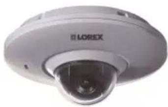
Front view of a white LOREX surveillance camera with lens and screen (no visible text or symbols beyond branding)Instruction Manual LNZ3522B HD MICRO PT DOME CAMERA
Thank you for purchasing this product. Lorex is committed to providing our customers with a high quality, reliable security solution.
This manual refers to the following models:
LNZ3522B
For the latest online manual, downloads and product updates, and to learn about our complete line of accessory products, please visit our website at:
www.lorextechnology.com
WARNING
RISK OF ELECTRIC SHOCK DO NOT OPEN

WARNING: TO REDUCE THE RICK OF ELECTRIC SHOCK DO NOT REMOVE COVER. NO USER SERVICABLE PARTS INSIDE.
REFER SERVICING TO QUALIFIED SERVICE PERSONNEL.
The lightning flash with arrowhead symbol, within an equilateral triangle, is intended to alert the user to the presence of uninsulated "dangerous voltage" within the product's enclosure that may be of sufficient magnitude to constitute a risk of electric shock.

The exclamation point within an equilateral triangle is intended to alert the user to the presence of important operating and maintenance (servicing) instructions in the literature accompanying the appliance.
WARNING: TO PREVENT FIRE OR SHOCK HAZARD, DO NOT EXPOSE THIS UNIT TO RAIN OR MOISTURE.
CAUTION: TO PREVENT ELECTRIC SHOCK, MATCH WIDE BLADE OF THE PLUG TO THE WIDE SLOT AND FULLY INSERT.
Table of contents
1 Safety Instructions ....1
2 LNZ3522B Features 2
3 Getting Started ....3
4 Camera Overview....4
5 Connecting the Camera ....5
5.1 OPTION 1: Connecting Cameras to an NVR.....5
5.2 OPTION 2: Connecting Cameras to the Local Area Network (LAN) ....5
6 Installation 10
6.1 Installation Tips and Warnings.... 10
6.2 Installation (Indoor/Outdoor).... 10
6.2.1 Ceiling Mounting.... 10
7 Controlling the PT Camera with an NVR 14
7.1 Controlling the Camera's Pan-Tilt Movement (Local NVR) 15
7.2 Advanced Pan-Tilt Controls.... 15
7.2.1 Presets.... 16
7.2.2 Tour (Not Supported) 17
7.2.3 Pattern (Not Supported) 17
7.2.4 Border (Not Supported).... 17
8 Technical Specifications .... 18
8.1 Dimensions 19
9 Troubleshooting.... 20
10 Resetting the Camera 22
11 Notices 24
11.1 FCC/IC Notice 24
11.2 Modification.... 24
11.3 ROHS 24
1 Safety Instructions
- Read this guide carefully and keep it for future reference.
- Follow all instructions for safe use of the product and handle with care.
- Use the camera within given temperature, humidity, and voltage levels noted in the Technical Specifications.
- Camera is rated for outdoor use and is weatherproof when properly installed. Camera is not intended for submersion in water. Installation under a sheltered environment is recommended.
- Do not disassemble the camera.
- Do not point the camera directly towards the sun or a source of intense light.
- Make sure to install the camera in a location that can support the camera weight.
- Make sure there are no live electrical cables in the area where you plan to mount the camera.
- Periodic cleaning may be required. Use a damp cloth only. Do not use anything other than water to clean the dome cover, as chemicals such as acetone can permanently damage the plastic.
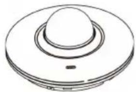
2 LNZ3522B Features
natural_image
Exterior view of a LOREX surveillance camera (no visible text or symbols on body)• High definition 1080p resolution 2.1 MP image sensor.
- Full 360° pan rotation for complete area coverage and 100° per second panning speed.
- Micro dome form factor only 5" in diameter and just over 2" tall.
• 25 programmable preset positions.
• Built-in microphone for listen-in audio.
- Wide angle 3.6mm lens with 90^ field of view.
- Single network cable setup for video, power and Pan/Tilt control.
- Program preset viewing points when connected to a compatible NVR.
- Remote control of the Pan/Tilt camera using a smartphone or tablet when connected to a compatible NVR.
- Digital wide dynamic range backlight compensation ensures clear images in high and low light areas.
• 3D DNR (Digital Noise Reduction) for clear accurate images.
- ClearNight imaging for superior low light performance.
- Weatherproof for outdoor & indoor installation (IP66 Rated).
- Extreme temperature performance (-4^ 140^ / -20^ 60^) .
• Vandal-proof heavy-duty durable metal housing.
- Simple installation with Power over Ethernet (PoE) CAT5e cable.
- CAT5 PoE extension cable included per camera.
- Expand your coverage with Ethernet cable up to 300' from the NVR.

NOTE
- Compatible with Lorex HD NVR LNR100 & LNR400 Series only.
- This camera features an ultra-low light sensitive image sensor and therefore does not feature Infra-Red LEDs. The camera requires ambient lighting (for example, street/building lighting, star or moon light) to render a night time image. In total darkness (zero Lux) the camera will not produce a night time image and therefore the camera should not be installed in areas with complete darkness.
- Not intended for submersion in water. Installation in a sheltered location recommended.
3 Getting Started
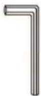
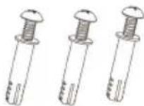
The system comes with the following components:
natural_image
Simple line drawing of a circular mechanical component with a central cylindrical top (no text or symbols)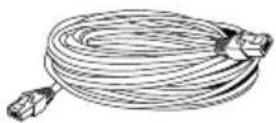
Micro PT Dome Camera Ethernet Extension Cable
natural_image
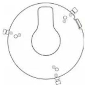
Simple line drawing of a circular object with internal structure and surrounding symbols (no text or labels)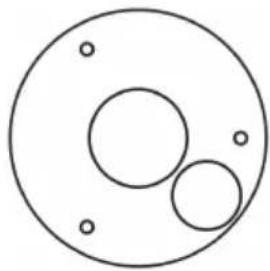
natural_image
Simple diagram of three concentric circles with small dots at the center (no text or symbols)Metal Mounting Plate Mounting Template

Instruction Manual
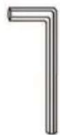
Allen Key
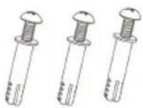
Mounting Screws & Anchors
(for mounting plate)
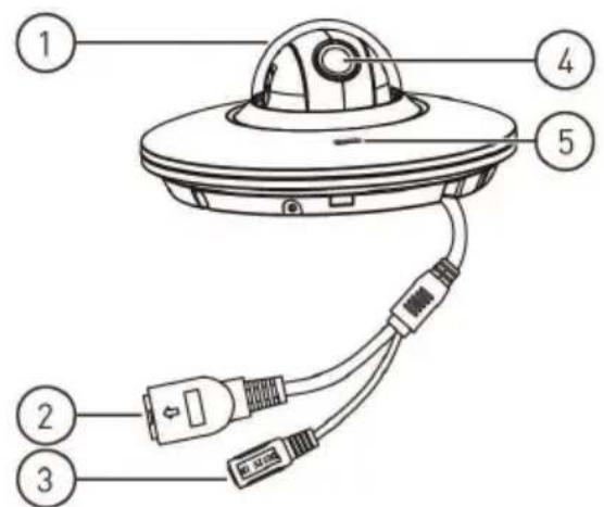
4 Camera Overview
text_image
Diagram of a flying saucer with labeled parts including a plug, connector, and cable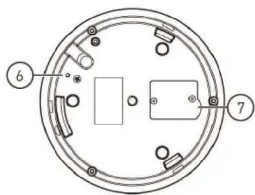
text_image
Technical diagram of a circular mechanical or electrical component with numbered parts labeled 6 and 7- Dome Cover
- Ethernet Port: Connect the camera to an NVR or PoE switch on your network using the included Ethernet cable.
- 12V DC Power: If not using PoE, connect the camera to a 12V DC power source (not included). Power adapters for this camera are available for purchase on www.lorextechnology.com (model #: CVA4902).
- Lens: Camera lens.
- Microphone: Built-in microphone.
- GND Port: The pre-inserted screw grounds the camera.
- Reset Button Compartment: Open using a Phillips screwdriver to reveal the reset button. Press and hold for 4 seconds to reset camera settings.
5 Connecting the Camera

NOTE
It is recommended to connect the camera to your NVR and test the Pan-Tilt controls before permanent installation. For instructions on how to setup Pan-Tilt controls, see 7 Controlling the PT Camera with an NVR, page 14.
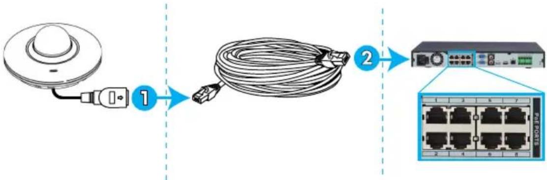
5.1 OPTION 1: Connecting Cameras to an NVR
flowchart
graph LR
    A["Device with cable"] -->|1| B["Cable with cable"]
    B -->|2| C["Network Interface with 7 ports"]
-
Connect the Ethernet connector on the camera cable to the included Ethernet extension cable.
-
Connect the Ethernet extension cable to one of the PoE ports on the back panel of your NVR.

NOTE
You can use a single CAT5e Ethernet cable up to 300ft (91m) to connect the camera to your NVR. The camera is compatible with Lorex LNR100 & LNR400 Series NVRs only.
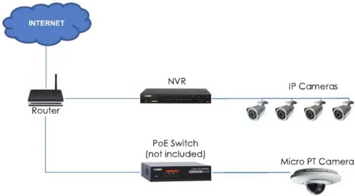
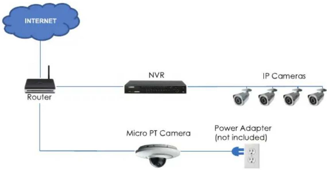
5.2 OPTION 2: Connecting Cameras to the Local Area Network (LAN)
For flexibility, you may also connect the camera to the same Local Area Network (LAN) as the NVR. This is accomplished by connecting the camera to the same router as the NVR. For these installations, an external PoE switch (sold separately) or power adapter (not included) must be used to provide power to the camera. You also must add the camera on the NVR before it will show a picture on the monitor or be recorded by the NVR.
What is PoE?
PoE (Power over Ethernet) is a technology that allows Ethernet cables to carry electrical power to connected devices. Compatible NVRs use integrated PoE
ports to provide power and Pan-Tilt commands to the camera, as well as video connection to the NVR. In order to use PoE with this IP camera, you must connect it directly to a compatible NVR (Lorex LNR100 & LNR400 Series only) or a PoE switch on the same network as the NVR.
PoE switches are available for purchase on www.lorextechnology.com.
Complete the following steps to connect the camera to the NVR over the LAN.
Step 1 of 2 — OPTION A: Connecting the camera to your local network using an optional PoE switch:
flowchart
graph TD
    A["INTERNET"] --> B["Router"]
    B --> C["NVR"]
    C --> D["IP Cameras"]
    C --> E["Micro PT Camera"]
    B --> F["PoE Switch (not included)"]
    F --> E
- Connect an Ethernet cable of up to 300ft (91m) rated CAT5e or higher (not included) from the LAN port on an external PoE switch (sold separately on www.lorextechnology.com) to your router. Connect the power cable to the PoE switch and to a power outlet or surge protector.

NOTE
Terminology may vary depending on the model of PoE switch you have.
- Connect the camera to the PoE switch using the included Ethernet cable (or a CAT5e Ethernet cable of up to 300ft (91m)). The PoE switch will provide power and video transmission the same way as your NVR.
Step 1 of 2 — OPTION B: Connecting the camera to your local network using a power adapter (not included):
flowchart
graph TD
    A["INTERNET"] --> B["Router"]
    B --> C["NVR"]
    C --> D["IP Cameras"]
    C --> E["Micro PT Camera"]
    E --> F["Power Adapter (not included)"]
    F --> G["Output"]
- Connect the camera to a 12V DC power adapter (sold separately on www.lorextechnology.com — model #: CVA4902).
- Connect the camera to a router in the same network as your NVR using the included Ethernet cable (or an Ethernet cable of up to 300ft (91m) rated CAT5e or higher).
Step 2 of 2: Add the camera to your NVR:

CAUTION
The following instructions are based on the Lorex LNR400 Series NVR. See your NVR's instruction manual for instructions on controlling the PTcamera with your system.
- Right-click and select Device Search .
-
Log in using the admin account (default User Name: admin; default Password: 000000).
-
Click Device Search. The system searches the network for compatible cameras.
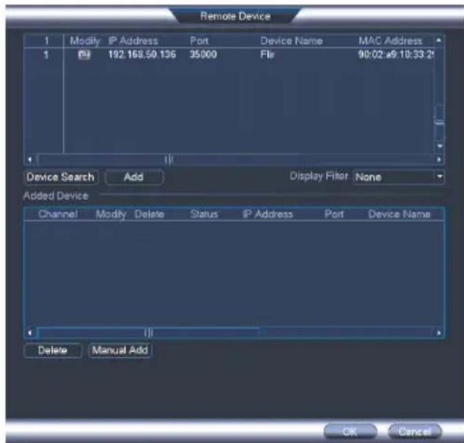
text_image
Remote Device 1 Modify IP Address Port Device Name MAC Address 1 F#: 192.168.50.136 35000 Flir 90:02:e9:10:33:2t Device Search Add Display Filter None Added Device Channel Modify Delete Status IP Address Port Device Name Delete Manual Add OK Cancel-
Check the camera(s) you would like to add.
-
Click Add. The Status indicator turns green to show the camera is successfully connected.
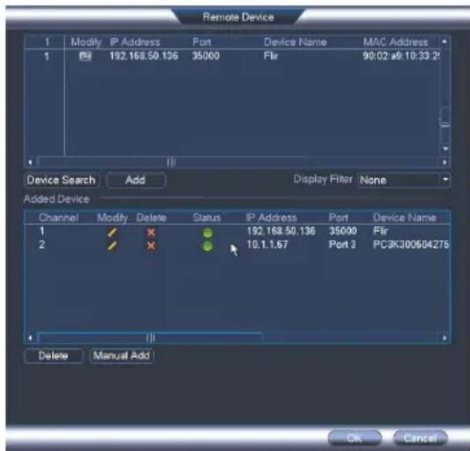
text_image
Remote Device 1 Modify IP Address Port Device Name MAC Address 1 192.168.50.136 35000 Flir 90:02 w9:10:33:2t Device Search Add Display Filter None Added Device Channel Modify Delete Status IP Address Port Device Name 1 ✓ ✗ 192.168.50.136 35000 Flir 2 ✓ ✗ 10.1.1.67 Port 3 PC3K300604275 Delete Manual Add OK Cancel6. Click OK to save changes.

NOTE
You can also add a camera to a specific channel by hovering the mouse over an empty channel in split-screen view and clicking. Then double-click the camera you would like to add and right click to exit.
6 Installation
6.1 Installation Tips and Warnings
- Camera is rated for outdoor use. It is recommended to install the camera in a sheltered area, such as under the eaves on a roof.
- Camera is capable of seeing in low light conditions (0.1 Lux), but it cannot see in total darkness. It is recommended to install the camera where there is some ambient light (for example, street lighting or starlight, moonlight, etc.) or leave some lighting on in the area where the camera is installed.
- Mount the camera in a location that can support the camera weight.
- Mount the camera where the lens is away from direct and intense sunlight.
- Plan your cable wiring so that it does not interfere with power lines or telephone lines.
- Ensure you adhere to local building codes.
- Ensure that the camera wiring is not exposed or easily cut.
- Mount the camera in an area that is visible but out of reach.
6.2 Installation (Indoor/Outdoor)

NOTE
The camera includes all necessary components for ceiling mounting only.
6.2.1 Ceiling Mounting
To ceiling mount the camera:
- Use the included mounting template to mark holes for the mounting screws and camera cable.
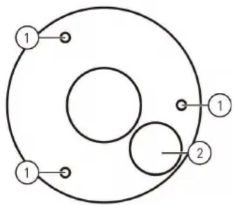
flowchart
graph TD
    A["1"] --> B["2"]
    B --> C["1"]
    style A fill:#fff,stroke:#000
    style B fill:#fff,stroke:#000
    style C fill:#fff,stroke:#000
-
Mounting screw holes; 2. Camera cable hole
-
Drill holes for the mounting screws, drywall anchors (optional) and camera cable.
| NOTE |
| Use the included drywall anchors if installing on a drywall surface.If you are planning on running the cables along the mounting surface, there is need to drill a hole for the camera cable. |
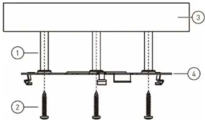
- Align the metal mounting plate so that the 3 screw holes in the plate line up with the 3 holes drilled in the ceiling. Attach the flat side of the metal mounting plate to the mounting surface using the included mounting screws (3x).
text_image
Technical diagram of a mechanical assembly with numbered components and screw placements-
Drywall anchors (3x — optional); 2. Mounting screws (3x); 3. Mounting surface; 4. Metal mounting plate
-
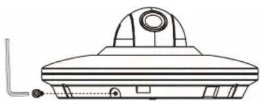
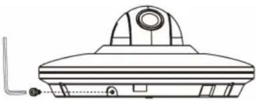
Remove the M2x5 screw from the side of the camera using the included Allen key.
natural_image
Technical line drawing of a mechanical component with a circular top and base (no text or symbols)-
Connect the camera cables as shown in 5 Connecting the Camera, page 5.
-
Align the 3 notches on the side of the dome camera with the pegs on the metal mounting plate. Push the camera gently into the mounting plate until it ‘clicks’.

CAUTION
If you are drilling a hole for the came cable, ensure that you run the cable through the cable hole in the metal mounting plate. See image below for reference:
ralf you run the cables along the mounting surface, you must run the cable through the cable notch on the camera base and underneath the metal mounting plate. This will keep the camera base flush to the surface when mounted. See image below for reference:
natural_image
Technical line drawing of a mechanical assembly with rotating components and wiring (no text or symbols)
natural_image
Technical line drawing of a circular mechanical component with mounting holes and a central hub (no text or symbols)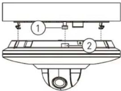
text_image
Technical diagram showing a mechanical assembly with labeled components 1 and 2, likely illustrating a lifting or mounting mechanism.- Pegs (x3); 2. Notches (x3)

NOTE
The pegs and notches only align one way. Do not force the camera to fit into the metal mounting plate.
- Re-insert the M2x5 screw removed in Step 4. Tighten firmly using the included Allen key.
natural_image
Technical line drawing of a mechanical component with no visible text or symbols- Remove the vinyl film from the dome cover once installation is complete.
7 Controlling the PT Camera with an NVR
The camera can accept Pan-Tilt commands directly through the Ethernet cable. There is no need to run special wiring to control the movement of the camera.

NOTE
- The following instructions are based on the Lorex LNR400 Series NVR. See your NVR's instruction manual for instructions on controlling the PT camera with your system.
- For the latest list of compatible NVRs, please visit www.lorextechnology.com/support.
To connect the camera to the system:
- Connect the camera to your NVR as detailed in 5 Connecting the Camera, page 5.
-
Right-click and click Main Menu. Enter the system user name (default: admin) and password (default: 000000) if prompted.
-
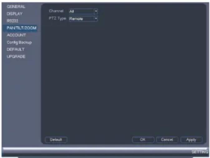
Click

Setting>Pan/Tilt/Zoom.
text_image
GENERAL DISPLAY RS232 PAN TLT/ZOOM ACCOUNT Config Backup DEFAULT UPGRADE Channel All PTZ Type Remote Default OK Cancel Apply SETTING- Under Channel, select the channel the micro PTcamera is connected to.
- Under PTZ Type, select Remote.
- Click OK. You can now control your micro PTcamera using the system.
7.1 Controlling the Camera's Pan-Tilt Movement (Local NVR)
- In Live View, double-click the channel that has the camera connected to open in full-screen.
- Right-click and click PTZ. Enter the system user name and password if prompted. The PTZ menu opens.
- Use the on-screen controls to control the camera.
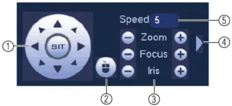
Pan-Tilt Controls
text_image
SIT Speed 5 Zoom Focus Iris ① ② ③ ④ ⑤- Direction keys: Click to pan and tilt the camera. Click SIT to stop the current action.
-
Mouse PT: Click to activate mouse Pan-Tilt mode. In mouse Pan-Tilt mode:
-
Click and drag to move the camera.
- Use the scroll wheel to zoom in and out.
-
Right-click to exit and return to normal Pan-Tilt controls.
-
Zoom/Focus/Iris: Click + / - next to Zoom to adjust the digital zoom level (up to 3x digital zoom). Focus and iris settings are not supported.
- Advanced controls: Click to open advanced Pan-Tilt controls.
- Not supported.
7.2 Advanced Pan-Tilt Controls
Advanced Pan-Tilt controls can be used to save camera positions and cycle through various positions, and automate camera actions.
To open advanced Pan-Tilt controls:
- Click the arrow in the Pan-Tilt control window to open advanced controls.

text_image
Speed 5 Zoom + Focus + Iris + → Speed 5 Zoom + Focus + Iris + No. 0Advanced Pan-Tilt controls overview:
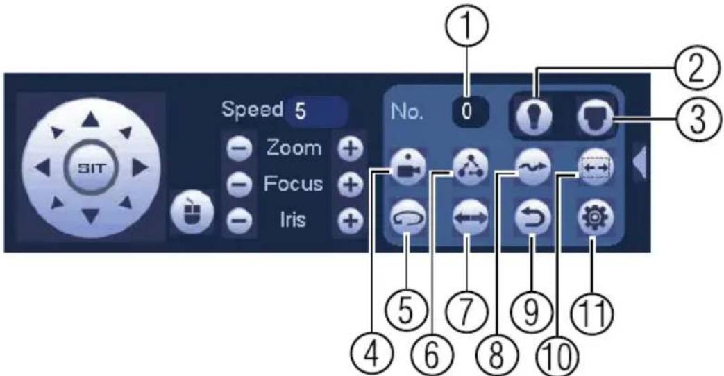
text_image
Speed 5 Zoom Focus Iris No. 0 ① ② ③ ④ ⑤ ⑥ ⑦ ⑧ ⑨ ⑩ ⑪- No.: Select the number of the action you want to perform.
- Not supported.
- Not supported.
- Preset: Click to call the selected preset.
- Not supported.
- Not supported.
- Not supported.
- Not supported.
- Not supported.
- Not supported.
- Aux: Click to open the aux menu, where you can set up Presets.
7.2.1 Presets
Presets will save a camera position for quick retrieval.
To add presets:
- Click

to open the aux menu.
2. Click the Preset tab.
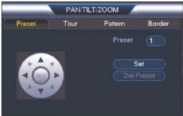
text_image
PAN/TILT/ZOOM Preset Tour Pattern Border Preset 1 Set Del Preset- Enter the number of the preset you want to create under Preset.
- Move the camera to the desired position and click Set.
To go to a preset:
• Under No., select the number of the preset you would like to go to and click

7.2.2 Tour (Not Supported)
7.2.3 Pattern (Not Supported)
7.2.4 Border (Not Supported)
8 Technical Specifications
| Image Sensor 1/3" 2.1MP | |
| Video Format | NTSC / PAL |
| Effective Pixels 1920 (H) x 1080 | (V) |
| Resolution Up to 1080p | |
| Range ±180° Pan; 90° Tilt | |
| Pan/Tilt Speed Max 100° / Sec | (Preset) |
| Zoom 3x Digital Zoom | |
| Min. Illumination 0.1 Lux in Black | and White |
| Lens / Lens Type 3.6mm F1.2 / | Fixed |
| Field of View (Horizontal) | 90° |
| Scan System Progressive | |
| Synchronization Internal | |
| Iris | AES |
| S / N Ratio >50dB (AGC Off) | |
| Termination | RJ45 10 / 100M Ethernet |
| Power Requirement | PoE (Power over Ethernet, Class ^1 3)12V DC |
| Power Consumption | Max. 220mA |
| Operating Temperature Range | -4°F ~ 140°F / -20°C ~ 60°C |
| Operating Humidity Range | Within 90%RH |
| Indoor/Outdoor | Both (IP66) ^2 |
| Weight | 0.25kg / 0.55lbs |
8.1 Dimensions
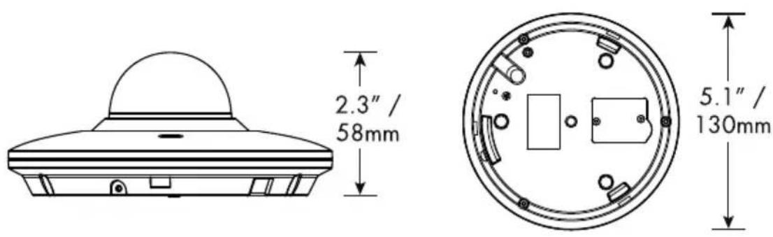
text_image
2.3" / 58mm 5.1" / 130mm9 Troubleshooting
There is no picture at night.
- Camera is capable of seeing in extremely low light conditions (0.1 Lux), but it cannot see in total darkness. It is recommended to install the camera where there is some ambient light (e.g. street lighting, starlight, moonlight, etc.) or leave a light on in the area where the camera is installed.
No image at startup.
- The camera may take up to 1 minute to power up after being connected to the NVR. Wait 2 minutes before following steps below.
- Check to ensure your camera is properly connected (see 5 Connecting the Camera, page 5).
- Ensure the camera is connected to a router on the same network as the NVR.
- If the camera is connected to the LAN, you must search your network for cameras using the NVR. See your NVR's instruction manual for details.
- Make sure that the cable run is within the limitations specified in 5 Connecting the Camera, page 5. All Ethernet cables must be rated CAT5e or higher.
- If using the power adapter, connect the power adapter to a different outlet.
- Ethernet cable may be damaged or not connected properly. Check your cable run or try a different cable.
- Reset the camera to factory default settings. See 10 Resetting the Camera, page 22 for details.
No image or camera image is unclear.
- Dome cover is dirty. Clean the dome cover with a soft, slightly damp cloth. Do not use anything other than water to clean the dome cover, as chemicals such as acetone can permanently damage the plastic.
Image is distorted.
- Digital zoom is activated. Activating digital zoom may reduce the resolution of the camera image. Zoom out completely to return to the camera's optimal resolution. See 7.1 Controlling the Camera's Pan-Tilt Movement (Local NVR), page 15 for instructions on using the zoom controls.
- Image may become unclear when camera is tilted too close to the camera base (e.g. pointed parallel to the ceiling). Tilt the camera using the NVR or in the FLIR Cloud™ Client software or mobile app.
Image is too bright.
- Ensure your camera isn't pointed directly at a source of light (e.g. sun or spot light).
- Check your NVR's brightness and contrast settings.
- Move your camera to a different location.
Image is too dark.
- Check your NVR's brightness and contrast settings.
- Move your camera to a different location.
NVR motion detection is constantly triggering.
- Turn off motion detection on the channel the micro PTcamera is connected to. NVRs use video motion detection, which means they detect motion by looking for changes between frames (images) in the video. If the camera is moving, the NVR will detect this as motion.
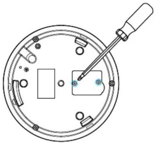
10 Resetting the Camera
The camera features a hard reset button that is used to reset all camera settings back to their default values. This is useful in case you've forgotten your login information or to revert camera image settings back to their default values.
To reset the camera:
-
Separate the camera from the mounting plate if needed and disconnect camera cables.
-
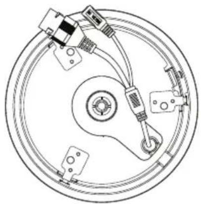
Remove the 2 screws from the compartment cover on the camera base using a Phillips screwdriver (not included).
natural_image
Technical line drawing of a mechanical assembly with a screwdriver inserted into a circular component (no text or symbols)- Press and hold the reset button for 4 seconds.
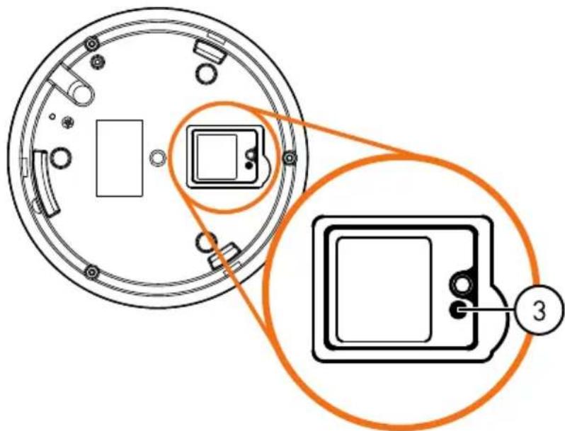
text_image
Diagram showing a circular device with internal components and an orange circle highlighting a labeled component '3'- Replace the compartment cover on the camera base.
11 Notices
This product has been certified and found to comply with the limits regulated by FCC, EMC, and LVD. Therefore, it is designated to provide reasonable protection against interference and will not cause interference with other appliance usage. However, it is imperative that the user follows the guidelines in this manual to avoid improper usage, which may result in damage to the product, electrical shock and fire hazard injury.
11.1 FCC/IC Notice
This equipment has been tested and found to comply with the limits for a Class B digital device, pursuant to Part 15 of the FCC Rules. These limits are designed to provide reasonable protection against harmful interference in a residential installation. This equipment generates, uses, and can radiate radio frequency energy and, if not installed and used in accordance with the instruction, may cause harmful interference to radio communications.
However, there is no guarantee that interference will not occur in a particular installation. If this equipment does cause harmful interference to radio or television reception (which can be determined by turning the equipment on and off), the user is encouraged to try to correct the interference by one or more of the following measures:
- Reorient or relocate the receiving antenna.
- Increase the separation between the equipment and receiver.
- Connect the equipment into an outlet on a circuit different from that to which the receiver is connected.
- Consult the dealer or an experienced radio or television technician for assistance.
11.2 Modification
Any changes or modifications not expressly approved by the grantee of this device could void the user's authority to operate the device.
This product is fully compliant with the European Union Restriction of the Use of Certain Hazardous Substances in Electrical and Electronic Equipment ("RoHS") Directive (2002/95/EC). The RoHS directive prohibits the sale of
electronic equipment containing certain hazardous substances such as lead, cadmium, mercury, and hexavalent chromium, PBB, and PBDE in the European Union.
Website
www.lorextechnology.com
Copyright
© 2015, Lorex Corporation
All rights reserved worldwide. Names and marks appearing herein are either registered trademarks or trademarks of Lorex Corporation and/or its subsidiaries. All other trademarks, trade names or company names referenced herein are used for identification only and are the property of their respective owners.
Legal disclaimer
As our product is subject to continuous improvement, Lorex Corporation & subsidiaries reserve the right to modify product design, specifications & prices without notice and without incurring any obligation.E&OE.
natural_image
Front view of a white LOREX surveillance camera with lens and screen (no visible text or symbols beyond branding)natural_image
Exterior view of a white Elorex surveillance camera (no visible text or symbols on body)natural_image
Simple line drawing of a circular mechanical component with a central cylindrical top (no text or symbols)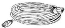
natural_image
Simple line drawing of a gourd-shaped object with surrounding small circles and rectangular elements (no text or symbols)natural_image
Simple diagram of three concentric circles with small dots at the center (no text or symbols)Modèle d'assemblage
text_image
Diagram of a flying saucer with labeled components including a plug, connector, and cable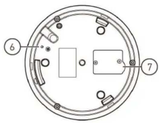
text_image
Technical diagram of a circular mechanical or electrical component with numbered parts labeled 6 and 7.flowchart
graph LR
    A["Device with cable"] -->|1| B["Cable cable"]
    B -->|2| C["Switch switch"]
    C --> D["Network Switch with four Ethernet ports"]
text_image
Remote Device 1 Modify IP Address Port Device Name MAC Address 1 192.168.50.136 35000 File 90:02:e9:10:33:21 Device Search Add Display Filter None Added Device Channel Modify Delete Status IP Address Port Device Name Delete Manual Add OK Canceltext_image
Remote Device 1 Modify IP Address Port Device Name MAC Address 1 192.168.50.136 35000 File 90:02:e9:10:33:21 Device Search Add Display Filter None Added Device Channel Modify Delete Status IP Address Port Device Name 1 ✓ ✗ 192.168.50.136 35000 Fir 2 ✓ ✗ 10.1.1.67 Port 3 PC3K300604275 Delete Manual Add OK Cancelflowchart
graph TD
    A["1"] --> B["Circle"]
    C["1"] --> D["Circle"]
    E["2"] --> F["Circle"]
    G["1"] --> H["Circle"]
    I["1"] --> J["Circle"]
text_image
Technical diagram of a mechanical assembly with numbered components and screw placementsnatural_image
Technical line drawing of a mechanical component with no visible text or symbolsnatural_image
Technical line drawing of a mechanical assembly with rotating components and mounting brackets (no text or symbols)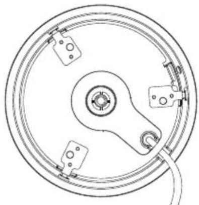
natural_image
Technical line drawing of a circular mechanical component with mounting holes and a central hub (no text or symbols)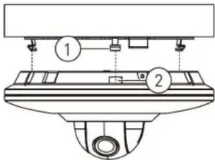
text_image
Technical diagram of a mechanical assembly with numbered components and alignment indicators- Broches (3); 2. Encoches(3x)

REMARQUE
natural_image
Technical line drawing of a mechanical component with a circular top and base, showing no text or symbols.text_image
GENERAL DISPLAY RS232 PAN'TLT/ZOOM ACCOUNT Config Backup DEFAULT UPGRADE Channel All PTZ Type Remote Default OK Cancel Apply SETTINGtext_image
Speed 5 Zoom Focus Iris No. 0 ① ② ③ ④ ⑤ ⑥ ⑦ ⑧ ⑨ ⑩ ⑪text_image
2.3" / 58mm 5.1" / 130mm9 Dépannage
natural_image
Technical line drawing of a mechanical assembly with a central component and a screwdriver (no text or symbols)natural_image
Diagram of a circular device with internal components and an orange circle highlighting a specific area, labeled with number 3 (no text or symbols present)© 2015, Lorex Corporation
natural_image
Front view of a white LOREX surveillance camera with lens and screen (no visible text or symbols beyond branding)natural_image
Exterior view of a white ElloREX surveillance camera (no text or symbols visible on body)natural_image
Simple line drawing of a circular object with a central oval and concentric rings (no text or symbols)natural_image
Simple line drawing of a teapot inside a circular frame with small geometric symbols around (no text or labels)natural_image
Simple diagram of three concentric circles with small dots at the center (no text or symbols)text_image
Diagram of a flying saucer with labeled components including a plug, connector, and cable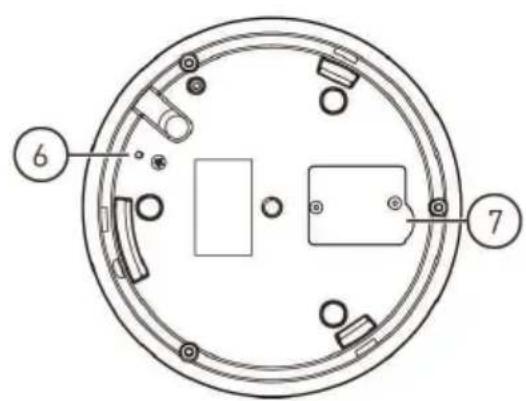
text_image
Technical diagram of a circular mechanical or electrical component with numbered parts labeled 6 and 7flowchart
graph LR
    A["Device with cable"] -->|1| B["Cable with USB port"]
    B -->|2| C["Network Interface with 6 ports and connected ports"]
text_image
Remote Device 1 Modify IP Address Port Device Name MAC Address 1 192.168.50.136 35000 File 90:02:e9:10:33:21 Device Search Add Display Filter None Added Device Channel Modify Delete Status IP Address Port Device Name Delete Manual Add OK Canceltext_image
Technical diagram showing a mechanical assembly with numbered components and screw placementsnatural_image
Technical line drawing of a mechanical component with no visible text or symbolsnatural_image
Technical line drawing of a mechanical assembly with rotating components and wiring (no text or symbols)natural_image
Technical line drawing of a circular mechanical component with mounting holes and a central hub (no text or symbols)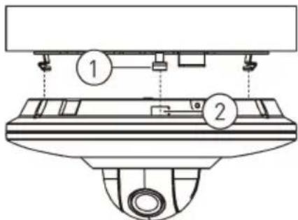
text_image
Technical diagram of a mechanical assembly with numbered components, likely a valve or pump assembly.- Clavijas (x3); 2. Ranuras (x3)

NOTA
natural_image
Technical line drawing of a mechanical component with no visible text or symbolstext_image
GENERAL DISPLAY RS232 PANTLT/ZOOM ACCOUNT Config Backup DEFAULT UPGRADE Channel All PTZ Type Remote Default OK Cancel Apply SETTINGtext_image
Speed 5 Zoom Focus Iris No. 0 ① ② ③ ④ ⑤ ⑥ ⑦ ⑧ ⑨ ⑩ ⑪text_image
2.3" / 58mm 5.1" / 130mmnatural_image
Technical line drawing of a mechanical assembly with a central component and a screwdriver (no text or symbols)text_image
Diagram showing a circular device with internal components and an orange circle highlighting a labeled component '3'© 2015, Lorex Corporation