
01923 - Bluetooth Receiver Vimar - Free user manual and instructions
Find the device manual for free 01923 Vimar in PDF.
| Product type | RF actuator/receiver for heating systems |
| Brand | Vimar |
| Model | 01923 |
| Category | Bluetooth receiver (RF 433.92 MHz) |
| Number of channels | 1 channel |
| Power supply | 230 V~ ±10% 50-60 Hz |
| Power consumption | 2 VA |
| Output type | 1 relay 6(2) A 250 V~ with changeover contact |
| Receiver frequency | 433.92 MHz |
| Sensitivity | -106 dBm |
| Antenna | 17 cm rigid wire (not supplied) or 433 MHz antenna with coaxial cable |
| Dimension (width) | 6 modules of 17.5 mm (105 mm) on DIN rail |
| Protection rating | IP40 |
| Electrical class | Class II |
| Operating temperature | 0 °C to +55 °C |
| Operating indicator | Green LED (power), red LEDs (channels and reception level) |
| Programming button | P button |
| Reception level | Indicated by number of red LEDs (1 to 4) |
| Reset procedure | Press and hold P button for 5 seconds (clears all memorizations) |
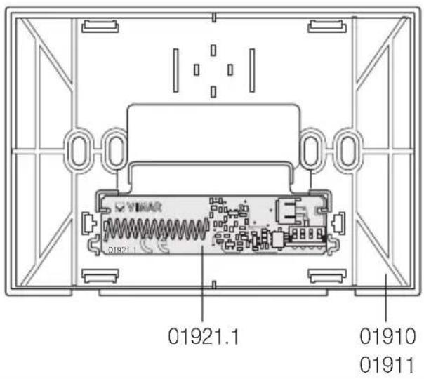
| With transmitter module | 01921.1 for replacement in chronothermostat 01910/01911 |
| Compatibility | Vimar chronothermostats 01910 and 01911 |
| Maintenance | Clean with a dry cloth; disconnect power before servicing |
| Safety | Installation by qualified personnel; disconnect power before servicing |
| Spare parts | Transmitter module 01921.1, 17 cm rigid wire antenna |
| Repairability | Repair only by an authorized professional |
Frequently Asked Questions - 01923 Vimar
User questions about 01923 Vimar
0 question about this device. Answer the ones you know or ask your own.
Ask a new question about this device
Download the instructions for your Bluetooth Receiver in PDF format for free! Find your manual 01923 - Vimar and take your electronic device back in hand. On this page are published all the documents necessary for the use of your device. 01923 by Vimar.
USER MANUAL 01923 Vimar
RF actuator/receiver
RF actuator/receiver 9
FRANÇAIS
8. CONFORMITÀ NORMATIVA.
Direttiva RED.
Norme EN 60730-2-7, EN 60730-2-9, EN 300 220-2, EN 301 489-3, EN 62311.
natural_image
Technical line drawing of an electronic device with connectors and coils (no text or symbols)5 - ITALIANO

- Description.... 10
- Operating mode.... 10
- Configuration of 01910 programmable chronothermostats.... 10
- Configuration of 01911 programmable chronothermostats.... 11
- Reset procedure 11
- Characteristics.... 12
- Installation rules 12
- Conformity to standards. 13
VIMAR
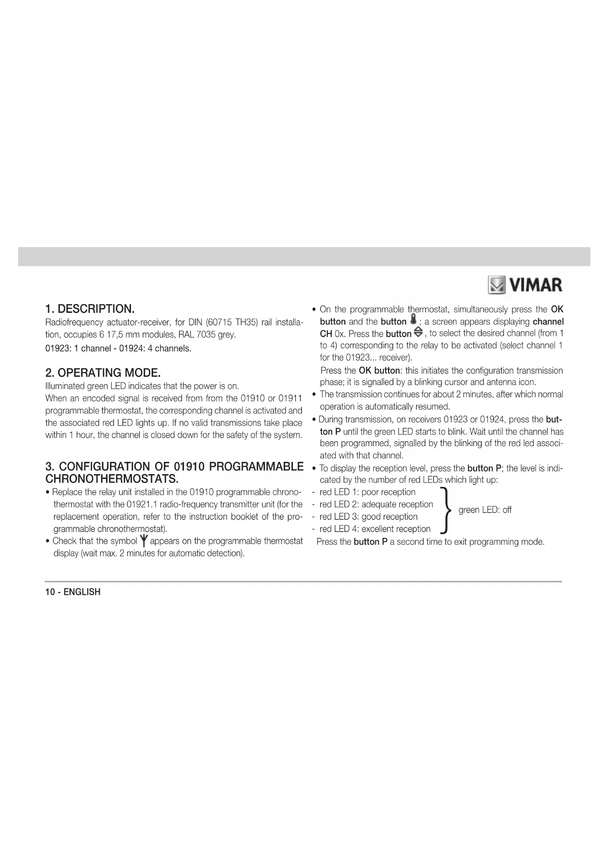
1. DESCRIPTION.
Radiofrequency actuator-receiver, for DIN (60715 TH35) rail installation, occupies 6 17,5 mm modules, RAL 7035 grey.
01923: 1 channel - 01924: 4 channels.
2. OPERATING MODE.
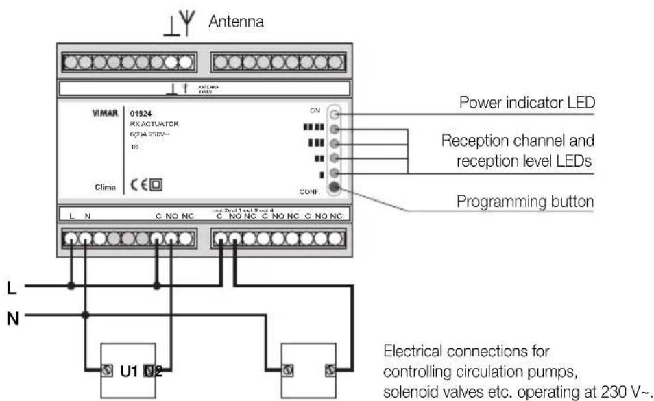
Illuminated green LED indicates that the power is on.
When an encoded signal is received from from the 01910 or 01911 programmable thermostat, the corresponding channel is activated and the associated red LED lights up. If no valid transmissions take place within 1 hour, the channel is closed down for the safety of the system.
3. CONFIGURATION OF 01910 PROGRAMMABLE CHRONOTHERMOSTATS.
- Replace the relay unit installed in the 01910 programmable chronothermostat with the 01921.1 radio-frequency transmitter unit (for the replacement operation, refer to the instruction booklet of the programmable chronothermostat).
-
Check that the symbol 🎨 appears on the programmable thermostat display (wait max. 2 minutes for automatic detection).
-
On the programmable thermostat, simultaneously press the OK button and the button ; a screen appears displaying channel CH 0x. Press the button , to select the desired channel (from 1 to 4) corresponding to the relay to be activated (select channel 1 for the 01923... receiver).
Press the OK button: this initiates the configuration transmission phase; it is signalled by a blinking cursor and antenna icon. - The transmission continues for about 2 minutes, after which normal operation is automatically resumed.
- During transmission, on receivers 01923 or 01924, press the button P until the green LED starts to blink. Wait until the channel has been programmed, signalled by the blinking of the red led associated with that channel.
-
To display the reception level, press the button P; the level is indicated by the number of red LEDs which light up:
-
red LED 1: poor reception
- red LED 2: adequate reception
- red LED 3: good reception
- red LED 4: excellent reception
Press the button P a second time to exit programming mode.

VIMAR
- To finish the procedure, press button C on the programmable thermostat. In the case of the 01924 four channel actuator-receiver, repeat the procedure to configure the other channels.
4. CONFIGURATION OF PROGRAMMABLE CHRONOTHERMOSTATS 01911.
- Replace the relay module in the timer-thermostat 01911 with the radio-frequency transmitter module 01921.1.
- On the timer-thermostat, go to the SETTINGS menu and select CONFIG. RF; the screen will show CONFIG. RF. Using the rotary knob, select the desired channel (from 1 to 4) corresponding to the relay you want to control (if using receiver 01923 always select channel 1). Press the ⚙ selection button; the configuration transmission phase commences.
- The transmission continues for 40 seconds, then the system stops the procedure and goes back to the CONFIG RF menu item. The transmission can be stopped manually by pressing the selection button a second time.
- During the transmission, on the receiver 01923 or 01924 press button P until the green LED blinks. Wait for channel programming to be signalled by the red LED corresponding to this channel blinking.
- To display the level of reception press button P until the green LED goes out; the level is shown by the number of red LEDs that light up:
- red LED 1: poor reception
- red LED 2: sufficient reception
- red LED 3: good reception
- red LED 4: optimum reception
Press button P until the green LED lights up again, to exit the programming phase.
- If it has not yet ended automatically, stop the timer-thermostat transmitting the configuration, press the ⚙ selection button. If using the 4-channel actuator 01924, repeat the procedure for each of the channels you want to configure.
5. RESET PROCEDURE.
Press and hold down the button P for 5 seconds; this will clear all the values stored in memory. The operation is signalled by the simultaneous blinking of all the red LEDs and the green LED.

6. PRINCIPAL CHARACTERISTICS.
• Supply voltage: 230 V\~ ±10% 50-60 Hz
• Power consumption: 2 VA
- Output:
- 01923: 1 relay 6(2) A 250 V with clean changeover contact
- 01924: 4 relays 6(2) A 250 V with clean changeover contact
• Receiver frequency range: 433.92 MHz
• Sensitivity: -106 dBm approx.
- Usable antenna:
- 17 cm rigid wire antenna (not supplied) to be positioned vertically and connected to terminal Y.
- 433 MHz antenna with coaxial cable connection (to be used when the antenna needs to be positioned at a distance, or where there are reception problems).
The rigid wire or antenna must always be assembled.
• Enclosure: six 17.5-mm modules for DIN (60715 TH35) rail mount
• Protection level: IP40
- Class II devices:
• Number of automatic cycles: 100.000
- Type of contact opening: micro-disconnect
- Type of action: 1B
- Tracking index: PTI175
• Pollution status: 2 (normal)
• Temperature: 0 °C +55 °C
• Temperature for shipping and storage: -25 °C +60 °C
• Rated pulse voltage: 4000 V.
- Software class: A.
7. INSTALLATION RULES.
- Installation should be carried out by qualified personnel in compliance with the current regulations regarding the installation of electrical equipment in the country where the products are installed.
- Disconnect the mains acting on the main switch before operating on the system.
- Use the yellow/green insulated conductors only for the connection to the earthing circuit.
- Verify if the supply conductors cross-sectional area is sufficient for the feeded load, in any case it must never be less than 1.5 ~mm^2 .
- Clamp fully, with care, the conductors in the terminals; faulty clampings can cause temperature rises high enough for a fire risk.

VIMAR
8. CONFORMITY TO STANDARDS.
RED Directive.
Standards EN 60730-2-7, EN 60730-2-9, EN 300 220-2, EN 301 489-3, EN 62311.
Vimar SpA declares that the radio equipment complies with Directive 2014/53/EU. The full text of the EU declaration of conformity is on the product sheet available at the following Internet address: www.vimar.com.
REACH (EU) Regulation no. 1907/2006 – Art.33. The product may contain traces of lead.
WEEE - Information for users
If the crossed-out bin symbol appears on the equipment or packaging, this means the product must not be included with other general waste at the end of its working life. The user must take the worn product to a sorted waste center, or return it to the retailer when purchasing a new one. Products for disposal can be consigned free of charge (without any new purchase obligation) to retailers with a sales area of at least 400 m², if they measure less than 25 cm. An efficient sorted waste collection for the environmentally friendly disposal of the used device, or its subsequent recycling, helps avoid the potential negative effects on the environment and people's health, and encourages the re-use and/or recycling of the construction materials.
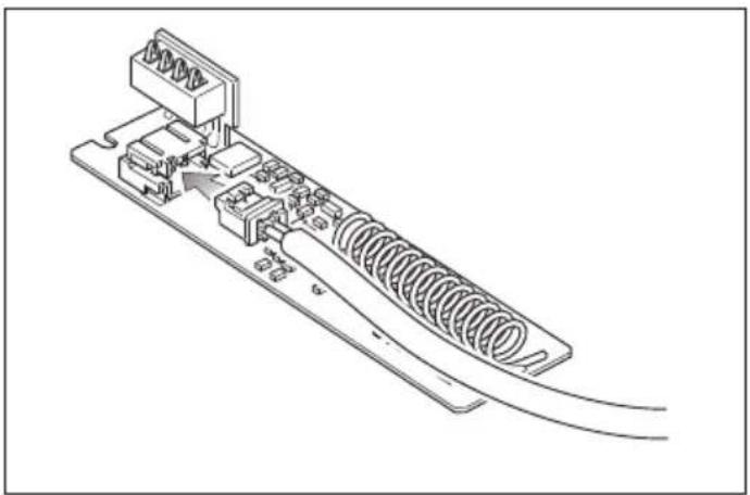
Remote operation via radiofrequency transmitter unit.
To switch on the programmable thermostat or thermostat from a remote location, use the cable which connects the radiofrequency transmitter unit to the telephone dialer with actuator.
01921.1
natural_image
Technical line drawing of a mechanical component with spring and housing (no text or symbols)
Remote operation via radiofrequency transmitter unit.

VIMAR
Connection example.
3. CONFIGURATION CHRONOTHERMOSTATS 01910.
8. CONFORMITE AUX NORMES.
Directive RED.
Normes EN 60730-2-7, EN 60730-2-9, EN 300 220-2, EN 301 489-3, EN 62311.
natural_image
Technical line drawing of a mechanical assembly with spring and housing components (no text or symbols)
natural_image
Technical line drawing of a mechanical component with springs and housing (no text or symbols)
natural_image
Technical line drawing of a mechanical component with springs and housing (no text or symbols)
natural_image
Technical line drawing of a mechanical assembly with springs and connectors (no text or symbols)

- FRANÇAIS
- CONFORMITÀ NORMATIVA.
- VIMAR
- DESCRIPTION.
- OPERATING MODE.
- CONFIGURATION OF 01910 PROGRAMMABLE CHRONOTHERMOSTATS.
- CONFIGURATION OF PROGRAMMABLE CHRONOTHERMOSTATS 01911.
- RESET PROCEDURE.
- PRINCIPAL CHARACTERISTICS.
- The rigid wire or antenna must always be assembled.
- INSTALLATION RULES.
- CONFORMITY TO STANDARDS.
- WEEE - Information for users
- Remote operation via radiofrequency transmitter unit.
- CONFIGURATION CHRONOTHERMOSTATS 01910.
- CONFORMITE AUX NORMES.
Brand : Vimar
Model : 01923
Category : Bluetooth Receiver