K400 - Drain cleaning machine RIDGID - Free user manual and instructions
Find the device manual for free K400 RIDGID in PDF.

| Product Type | Drain Cleaning Machine |
| Brand | RIDGID |
| Model | K-400 |
| Dimensions (Handle Down) | 19.75 x 17.25 x 22.6 in (500 x 440 x 575 mm) |
| Weight (Machine Only) | 40 lb (18 kg) |
| Weight (with 3/8" x 75' cable, no feed) | 66 lb (30 kg) |
| Motor Type | Induction, 1/3 HP, 5A (120V) or 230W, 2.5A (220-240V) |
| No-Load Speed (120V) | 170 RPM |
| No-Load Speed (220-240V) | 140 RPM |
| Drum Capacity | 100 ft (30.5 m) of 3/8" (10 mm) cable or 75 ft (22.5 m) of 1/2" (12 mm) cable |
| Line Capacity | 1.5" - 4" (40 - 100 mm) diameter |
| Max Cable Extension Without Guide | 2 ft (0.6 m) from drain inlet |
| Control | FOR/OFF/REV rocker switch, pneumatic foot switch |
| Power Supply | 120V~ 60Hz or 220-240V~ 50Hz, grounded with GFCI |
| Standard Equipment | One pair RIDGID Drain Cleaning Gloves, T-202 Bulb Auger, T-205 C Cutter, T-211 Spade Cutter, A-13 Pin Key |
| Safety Features | GFCI on power cord, belt guard, torque limiter, foot switch |
| Operating Temperature | 20°F to 140°F (-6°C to 60°C) |
| Sound Pressure Level | 84.8 dB(A), K=3 |
| Warranty | Full Lifetime Warranty against defects |
| Certifications | UL 62841-1, CSA C22.2, CE |
Frequently Asked Questions - K400 RIDGID
User questions about K400 RIDGID
0 question about this device. Answer the ones you know or ask your own.
Ask a new question about this device
Download the instructions for your Drain cleaning machine in PDF format for free! Find your manual K400 - RIDGID and take your electronic device back in hand. On this page are published all the documents necessary for the use of your device. K400 by RIDGID.
USER MANUAL K400 RIDGID
Drain Cleaning Machine
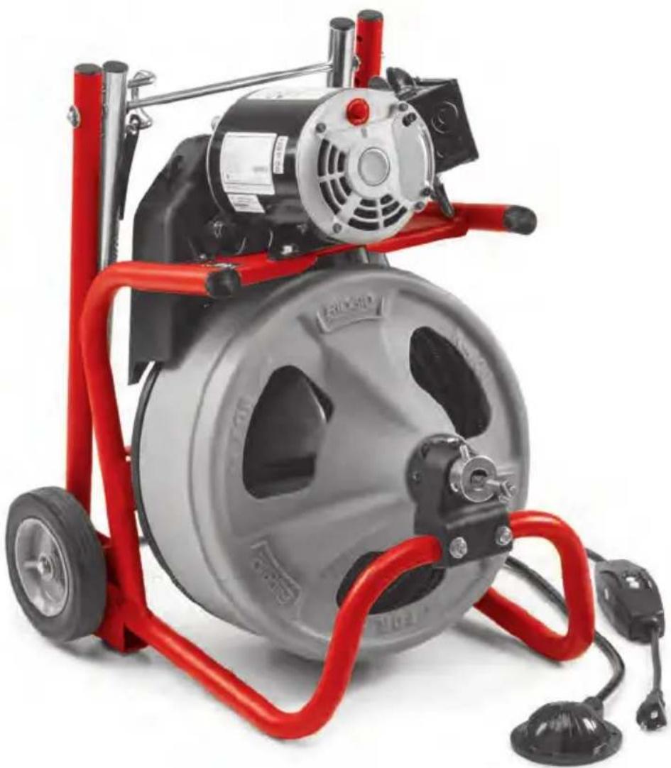
natural_image
Exterior view of a red and silver electric pressure vessel with attached motors and wheels (no visible text or symbols)Table of Contents
Recording Form for Machine Serial Number....1
Safety Symbols 2
General Power Tool Safety Warnings
Work Area Safety 2
Electrical Safety 2
Personal Safety....3
Power Tool Use and Care ....3
Service....4
Specific Safety Information
Transportable Drain Cleaner Safety Warnings....4
Description, Specifications and Standard Equipment
Description 5
Specifications....5
Standard Equipment 6
Machine Assembly
Installing Wheels....6
Mounting AUTOFEED® Cable Feed (Optional Equipment) 6
Attaching Front Guide Hose (Optional Equipment)....7
Pre-Operation Inspection....7
Machine and Work Area Set Up....9
Operating Instructions
Operation....12
Feeding the Cable into the Drain 12
Passing Through Traps or Other Transitions 13
Cleaning the Drain....13
43
Handling a Stuck Tool 14
Freeing a Stuck Tool 14
Retrieving the Cable 14
Using Machine with a Front Guide Hose 15
Maintenance Instructions
Cleaning....15
Cables....16
AUTOFEED Cable Feed 16
Lubrication....16
Front Guide Hose....16
Belt Removal/Installation 16
Torque Limiter Adjustment 16
Replacing Cable....17
Optional Equipment....17
Machine Storage 17
Service and Repair....17
Disposal....18
Troubleshooting....19
EC Declaration of Conformity....Inside Back Cover
Lifetime Warranty....Back Cover
*Original Instructions - English
Drain Cleaning Machine
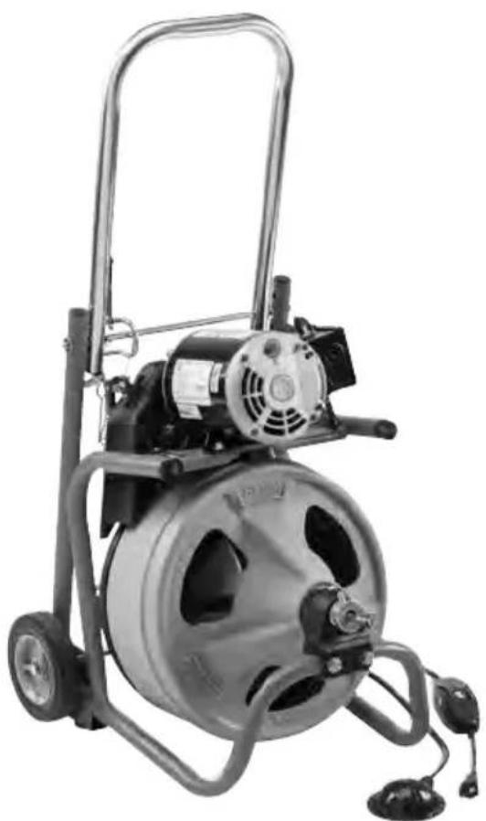
natural_image
Industrial electric pump with motor and wheels (no visible text or symbols)
natural_image
Exterior view of a portable electric vacuum cleaner with control panel and wheels (no visible text or symbols)
WARNING
Read this Operator's Manual carefully before using this tool. Failure to understand and follow the contents of this manual may result in electrical shock, fire and/or serious personal injury.
K-400 Drain Cleaning Machine
| Record Serial Number below and retain product serial number which is located on nameplate. | |
| Serial No. | |
Safety Symbols
In this operator's manual and on the product, safety symbols and signal words are used to communicate important safety information. This section is provided to improve understanding of these signal words and symbols.

This is the safety alert symbol. It is used to alert you to potential personal injury hazards. Obey all safety messages that follow this symbol to avoid possible injury or death.

DANGER indicates a hazardous situation which, if not avoided, will result in death or serious injury.

WARNING indicates a hazardous situation which, if not avoided, could result in death or serious injury.

CAUTION indicates a hazardous situation which, if not avoided, could result in minor or moderate injury.

ICE NOTICE indicates information that relates to the protection of property.

This symbol means read the operator's manual carefully before using the equipment. The operator's manual contains important information on the safe and proper operation of the equipment.

This symbol means always wear safety glasses with side shields or goggles when handling or using this equipment to reduce the risk of eye injury.

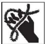
This symbol indicates the risk of hands, fingers or other body parts being caught, wrapped or crushed in the drain cleaning cable.

This symbol indicates the risk of electrical shock.

This symbol indicates the risk of entanglement in a belt and pulley.
General Power Tool Safety Warnings\*
WARNING
Read all safety warnings, instructions, illustrations and specifications provided with this power tool. Failure to follow all instructions listed below may result in electric shock, fire and/or serious injury.
SAVE ALL WARNINGS AND INSTRUCTIONS FOR FUTURE REFERENCE!
The term "power tool" in the warnings refers to your mains-operated (corded) power tool or battery-operated (cordless) power tool.
Work Area Safety
- Keep work area clean and well lit. Cluttered or dark areas invite accidents.
- Do not operate power tools in explosive atmospheres, such as in the presence of flammable liquids, gases, or dust. Power tools create sparks which may ignite the dust or fumes.
- Keep children and bystanders away while operating a power tool. Distrac-tions can cause you to lose control.
Electrical Safety
- Power tool plugs must match the outlet. Never modify the plug in any way. Do not use any adapter plugs with earthed (grounded) power tools. Unmodi fied plugs and matching outlets will reduce risk of electric shock.
- Avoid body contact with earthed or ground ed surfaces such as pipes, ra dia-tors, ranges and re friger ators. There is an increased risk of electric shock if your body is earthed or grounded.
- Do not expose power tools to rain or wet conditions. Water entering a power tool will increase the risk of electric shock.
-
Do not abuse the cord. Never use the cord for carrying, pulling or unplugging the power tool. Keep cord away from heat, oil, sharp edges or moving parts. Damaged or entangled cords increase the risk of electric shock.
-
When operating a power tool outdoors, use an extension cord suitable for outdoor use. Use of a cord suitable for outdoor use reduces the risk of electric shock.
- If operating a power tool in a damp location is unavoidable, use a ground fault circuit interrupter (GFCI) protected supply. Use of a GFCI reduces the risk of electric shock.
Personal Safety
- Stay alert, watch what you are doing and use common sense when operating a power tool. Do not use a power tool while you are tired or under the influence of drugs, alcohol or medication. A moment of inattention while operating power tools may result in serious personal injury.
- Use personal protective equipment. Always wear eye protection. Protective equipment such as dust mask, non-skid safety shoes, hard hat, or hearing protection used for appropriate conditions will reduce personal injuries.
- Prevent unintentional starting. Ensure the switch is in the OFF-position before connecting to power source and/or battery pack, picking up or carrying the tool. Carrying power tools with your finger on the switch or energizing power tools that have the switch ON invites accidents.
- Remove any adjusting key or wrench before turning the power tool ON. A wrench or a key left attached to a rotating part of the power tool may result in personal injury.
- Do not overreach. Keep proper footing and balance at all times. This enables better control of the power tool in unexpected situations.
- Dress properly. Do not wear loose clothing or jewelry. Keep your hair and clothing away from moving parts. Loose clothes, jewelry or long hair can be caught in moving parts.
- If devices are provided for the connection of dust extraction and collection facilities, ensure these are connected and properly used. Use of dust collection can reduce dust-related hazards.
- Do not let familiarity gained from frequent use of tools allow you to become complacent and ignore tool safety prin-
ciples. A careless action can cause severe injury within a fraction of a second.
- This appliance is not intended for use by persons (including children) with reduced physical, sensory or mental capabilities, or lack of experience and knowledge, unless they have been given supervision or instruction concerning use of the appliance by a person responsible for their safety.
- Children should be supervised to ensure that they do not play with the appliance.
Power Tool Use and Care
- Do not force the power tool. Use the correct power tool for your application. The correct power tool will do the job better and safer at the rate for which it was designed.
- Do not use the power tool if the switch does not turn it ON and OFF. Any power tool that cannot be controlled with the switch is dangerous and must be repaired.
- Disconnect the plug from the power source and/or remove the battery pack, if detachable, from the power tool before making any adjustments, changing accessories, or storing power tools. Such preventive safety measures reduce the risk of starting the power tool accidentally.
- Store idle power tools out of the reach of children and do not allow persons unfamiliar with the power tool or these instructions to operate the power tool.
^1e Power tools are dangerous in the hands of untrained users.
- Maintain power tools. Check for misalignment or binding of moving parts, breakage of parts and any other condition that may affect the power tool's operation. If damaged, have the power tool repaired before use. Many accidents are caused by poorly maintained power tools.
- Keep cutting tools sharp and clean. Pro -perly maintained cutting tools with sharp cutting edges are less likely to bind and are easier to control.
- Use the power tool, accessories and tool bits etc. in accordance with these instructions, taking into account the working conditions and the work to be performed. Use of the power tool for operations different from those intended could result in a hazardous situation.
- Keep handles and grasping surfaces dry, clean and free from oil and grease. Slippery handles and grasping surfaces do not allow for safe handling and control of the tool in unexpected situations.
Service
- Have your power tool serviced by a qualified repair person using only identical replacement parts. This will ensure that the safety of the power tool is maintained.
Specific Safety Information
WARNING
This section contains important safety information that is specific to this tool.
Read these precautions carefully before using the K-400 Drain Cleaning Machine to reduce the risk of electrical shock or other serious personal injury.
SAVE THESE INSTRUCTIONS!
Keep this manual with the machine for use by the operator. The manual can be hung on the machine.
Transportable Drain Cleaner Safety Warnings
- Before using the tool, test the ground fault circuit interrupter (GFCI) provided with the power supply cord to insure it is operating correctly. A properly operating GFCI reduces the risk of electrical shock.
- Only use extension cords that are protected by an GFCI. The GFCI on the machine power cord will not prevent electrical shock from extension cords.
- Only grasp the rotating cable with gloves recommended by the manufacturer. Latex or loose fitting gloves or rags can become wrapped around the cable and may result in serious personal injury.
- Do not allow the cutter to stop turning while the cable is turning. This can over-stress the cable and may cause twisting, kinking or breaking of the cable and may result in serious personal injury.
- One person must control both the cable and the power switch. If the cutter stops rotating, the operator must be able to turn the tool OFF to prevent the cable from twisting, kinking and breaking.
- Use latex or rubber gloves inside the gloves recommended by the manufacturer, goggles, face shields, protective clothing, and respirator when chemicals, bacteria or other toxic or infectious substances are suspected to be in a drain line. Drains may contain chemicals, - bacteria and other substances that may cause burns, be toxic or infectious or may result in other serious personal injury.
- Practice good hygiene. Do not eat or smoke while handling or operating the tool. After handling or operating drain cleaning equipment, use hot, soapy water to wash hands and other body parts exposed to drain contents. This will help reduce the risk of health hazards due to exposure to toxic or infectious material.
- Only use the drain cleaner for the recommended drain sizes. Using the wrong size drain cleaner can lead to twisting, kinking or breaking of the cable and may result in personal injury.
- Never operate machine with the belt guard removed. Fingers can be caught between the belt and pulley.
- Keep gloved hand on the cable whenever the machine is running. This provides better control of the cable and helps prevent twisting, kinking and breaking of the cable. Twisting, kinking or breaking cable may cause striking or crushing injuries.
Position machine within two feet of the drain inlet or properly support exposed cable when the distance exceeds two feet. Greater distances can cause control problems leading to twisting, kinking or breaking of the cable. Twisting, kinking or breaking cable may cause striking or crushing injuries.
- Do not operate the machine in REV (reverse) rotation except as described in this manual. Operating in reverse can result in cable damage and is used to back the tool out of blockages.
- Keep hands away from rotating drum and guide tube. Do not reach into drum unless machine is unplugged. Hand may be caught in the moving parts.
- Do not wear loose clothing or jewelry. Keep your hair and clothing away from moving parts. Loose clothing, jewelry or hair can be caught in moving parts.
- Do not operate this machine if operator or machine is standing in water. Oper -
ating machine while in water increases the risk of electrical shock.
If you have any question concerning this RIDGID® product:
- Contact your local RIDGID distributor.
- Visit RIDGID.com to find your local RIDGID contact point.
- Contact Ridge Tool Technical Service Department at rttechservices@emer son.co or in the U.S. and Canada call (800) 519-3456.
Description, Specifications and Standard Equipment
Description
The RIDGID ^® K-400 Drain Cleaning Machine will clean drain lines from 1/2" to 4" (40 to 100mm) in diameter and 100 feet (30,5m) in length depending on size of the cable. Corrosion-resistant cable drum holds 75 feet (22,5m) of 1/2" (12mm) diameter cable or 100 feet (30,5m) of 3/8" (10mm) diameter cable. Cable spins at 170 RPM. The K-400 is not designed to remove root blockages.
The drum is belt-driven by a ^1/3 HP electric motor that has a grounded electrical system. An integral Ground Fault Circuit Interrupter (GFCI) is built into the line cord. A FOR/OFF REV (or 1/OFF/2) switch controls drum and cable rotation and a pneumatic foot switch provides ON/OFF control of the motor.
The cable control system consists of a torque limiter to stop the drum from rotating when the tool stops rotating and the torque exceeds the set value. This helps to prevent cable damage from cable flip over in the drum. The torque limiter is designed to work with RIDGID ^3/8 " and ^1/2 " integral wound (IW) cable, and may not protect other cables.
The "Solid-Core" Integral Wound cable is durable and kink-resistant. The cable has a quick change coupling system for connecting or disconnecting tools.
The optional AUTOFEED® cable feed allows the cable to be advanced or retrieved at a rate of 12-15 feet per minute (3.6-4.6 m/minute).
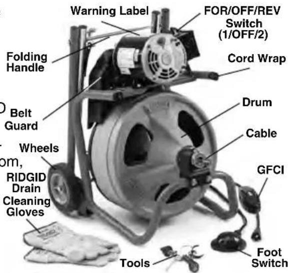
text_image
Warning Label FOR/OFF/REV Switch (1/OFF/2) Folding Handle Cord Wrap Dram Belt Guard Cable Wheels om, RIDGID Drain Cleaning Gloves Tools Foot SwitchFigure 1 – K-400 Drum Machine
Specifications
Line Capacity.....1½" - 3" (40mm - 75mm) Line with 3/8" (10mm) Cable 3" - 4" (75mm - 100mm) Line with ½" (12mm) Cable The K-400 is not designed to remove root blockages
Drum Capacity ...100' (30,5m) of 38 " (10mm) Diameter Cable 75' (22,5m) of 12 " (12mm) Diameter Cable
Motor Type......Induction '120V\~ Motor ......1/3 HP, 5A, 60Hz 220-240V\~
Motor.....230W, 2.5 A, 50 Hz
No Load Speed (n) 120V\~......170 RPM 220-240V\~ ......140 RPM
^a Control ......Rocker Type for- ue FOR/OFF/REV switch and pneumatic foot switch. Some units have 1/OFF/2 not Rotary Switch in place of Rocker Switch.
Sound Pressure ( I_B )*.....84.8 dB(A), K=3 Sound Power ( I_WA )*.....71.3 dB(A), K=3
Sound measurements are measured in accordance with a standardized test per Standard EN 62481-1.
- Sound emissions may vary due to your location and specific use of these tools.
- Daily exposure levels for sound need to be evaluated for each application and appropriate safety measures taken when needed. Evaluation of exposure levels should consider the time a tool is switched off and not in use. This may significantly reduce the exposure level over the total working period.
Operating
Temperature.....20°F to 140°F (-6°C to 60°C
Weight
(Machine Only)...40 lbs (18 kg)
(with ^3/_8 " x 75' Cable, w/o
cable feed) .....66 lbs (30 kg)
Dimensions:
Length.....19.75" (500 mm)
Width.....17.25" (440 mm)
Height .....22.6" (575mm) Handle
Down, 37.4" (930mm)
Handle Up
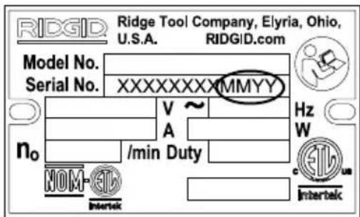
text_image
RIDGE Tool Company, Elyria, Ohio, U.S.A. RIDGiD.com Model No. Serial No. XXXXXXXXXXMMYY Hz W V ~ A no /min Duty NOM-ETI Intertek c InterbekFigure 2 – Machine Serial Number
The machine serial number is located on moto table. The last 4 digits indicate the month and year of the manufacture (MMYY).
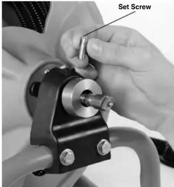
Remove and discard the 5/6" x 1" cable lock set screw from the Set Collar Assembly. The cable lock set screw is provided during packaging to keep the cable from coming out of the drum during transport (Figure 3).
text_image
Set ScrewFigure 3 – Remove and discard the Cable Lock Set Screw
Standard Equipment
All K-400 Drain Cleaning Machines come with one pair of RIDGID Drain Cleaning Gloves.
NOTICE This machine is made to clean drains. If properly used it will not damage a drain that is in good condition and properly designed, constructed and maintained. If the drain is in poor condition, or has not been properly designed, constructed and maintained, the drain cleaning process may not be effective or could cause damage to the drain. The best way to determine the condition of a drain before cleaning is through visual inspection with a camera. Improper use of this drain cleaner can damage the drain cleaner and the drain. This machine may not clear all blockages.
Machine Assembly
WARNING
To reduce the risk of serious injury during use, follow these procedures for proper assembly.
FOR/OFF/REV switch should be OFF and machine unplugged before assembly.
Installing Wheels
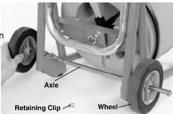
- Install retaining clip into groove on one end of axle.
- Slide one wheel onto axle with the boss away from the clip. (See Figure 4.)
- Fully insert axle through hole in bracket.
- Slide second wheel onto axle, boss first.
- Install retaining clip into groove.
text_image
Axle Retaining Clip WheelFigure 4 – Assembling Wheel
Mounting AUTOFEED® Cable Feed (Optional Equipment)
-
If needed, remove and discard cable lock set screw from the set collar. (See Figure 3.)
-
Pull approximately 6" (150mm) of cable from the machine.
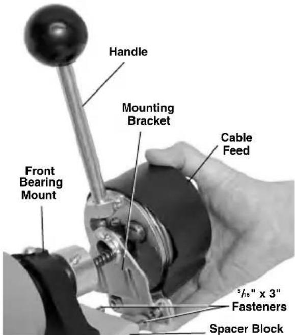
- Securely screw handle in place (Figure 5)
- Remove fasteners holding front bearing mount to frame. (See Figure 5.) Replace with supplied 516 " x 3" fasteners. Install spacer block over fasteners. Confirm mounting bracket properly placed on ba of cable feed. Install bracket and cable feed over cable and securely tighten fasteners.
text_image
Handle Mounting Bracket Cable Feed Front Bearing Mount 5/16" x 3" Fasteners Spacer BlockFigure 5 – Mounting Cable Feed onto the Frame
Attaching Front Guide Hose (Optional Equipment)
- Remove the three (3) cover screws from the front of the cable feed. Keep cover in place.
- Route the cable through the guide hose adapter. Attach the guide hose adapter to front of cable feed using existing screws, do not include flat washers. DO NOT OVERTIGHTEN.
- Pull approximately 2' (0.6m) of cable from the drum. Feed the cable into the coupling end of the guide hose and through the hose.

text_image
Cover Cover Screw Lock Nut Guide Hose Guide Hose AdapterFigure 6 – Mounting Guide Hose To Cable Feed
- Screw the guide hose coupling onto adapter. Position hose so that the natural curve of the hose follows the path to the drain. Tighten lock nut to keep hose from rotating. (See Figure 6.)
Pre-Operation Inspection
WARNING


Before each use, inspect your drain cleaning machine and correct any problems to reduce the risk of serious injury from electric shock, twisted or broken cables, chemical burns, infections and other causes and prevent drain cleaner damage.
Always wear safety glasses, and other appropriate protective equipment when inspecting your drain cleaner.
- Inspect the RIDGID drain cleaning gloves or mitts ("gloves"). Make sure they are in good condition with no holes, tears or loose sections that could be caught in the rotating cable. It is important not to wear improper or damaged gloves. The gloves protect your hands from the rotating cable. If the gloves are not RIDGID drain cleaning gloves or are damaged or worn out, do not use machine until RIDGID drain cleaning gloves are available. See Figure 7.

natural_image
Three different types of industrial gloves, one with a visible label 'RIOGID 60' and the other with black covers (no text or symbols on gloves themselves)Figure 7 – RIDGID Drain Cleaning Gloves – Leather, PVC
- Make sure that the drain cleaning machine is unplugged and inspect the power cord, Ground Fault Circuit Interrupter (GFCI) and plug for damage. If the plug has been modified, is missing the grounding prong or if the cord is damaged, to avoid electrical shock, do not use the machine until the cord has been replaced by a qualified repair person.
- Clean the drain cleaner, including handles and controls. This aids inspection and helps prevent the machine or control from slipping from your grip. Clean and maintain the machine per the maintenance instructions.
- Inspect the drain cleaning machine for the following items:
• Proper assembly and completeness.
- Any broken, worn, missing, misaligned or binding parts. Rotate the drum and make sure that it turns freely.
- Make sure the foot switch is attached to the drain cleaning machine. Do not operate the machine without the foot switch.
- Check the belt guard to insure that it is securely fastened to the drain cleaner. Do not operate without guard in place. See Figure 1.
• Presence and readability of the warning label (see Figure 8).
- Inspect the cable feed. Handle should move smoothly and freely throughout range. Con firm that handle returns to neutral position when re leased (Figure 14). Confirm AUTOFEED cover is securely in place.
- Any condition which may prevent safe and normal operation.
If any problems are found, do not use the drain cleaner until the problems have been repaired.
- Clean any debris from the cable and cutting tools. Inspect cable for wear and damage. Cable coupling plunger pin should
move freely and fully extend to securely retain tools. Inspect cable for:
- Obvious flats worn into the outside of the cable (ca ble is made from round wire and the profile should be round).
- Multiple or excessively large kinks (slight kinks up to 15 degrees can be straightened)
- Uneven spacing between cable coils indicating that the cable has been deformed by stretching, kinking, or running in reverse (REV)
- Excessive corrosion from storing wet or exposure to drain chemicals.
All of these forms of wear and damage weaken the cable and make cable twisting, kinking or breaking more likely during use. Replace worn and damaged cable before using drain cleaner.
Make sure the cable is fully retracted with no more than 6" (150mm) of cable outside of the machine. This will prevent whipping of the cable at start up.
- Inspect the tools for wear and damage. If necessary, replace prior to using the drain cleaning machine. Dull or damaged cutting tools can lead to binding, cable breakage, and slow the drain cleaning process..
- Make sure that the FOR/OFF/REV switch is set to the OFF position.
- With dry hands, plug cord into properly grounded outlet. Test the GFCI provided in the electrical cord to insure that it is operating correctly. When the test button is pushed in, the indicator light should go off. Reactivate by pushing the reset button in. If the indicator light goes on, the GFCI is functioning properly. If GFCI is not functioning properly, unplug the cord and do not use the drain cleaning machine until the GFCI has been repaired.
- Move the FOR/OFF/REV switch into the FOR position. Press the foot switch and note the direction of rotation of the drum. If the foot switch does not control the machine operation, do not use the machine until the foot switch has been repaired. The drum should rotate counter-clockwise when viewed from the front of the drum, and will match the drum direction shown on the warning label (Figure 8).
Release the foot switch and let the drum come to a complete stop. Place the FOR/ - OFF/REV switch into the REV position,
and repeat above testing to confirm that the drain cleaner operates properly in reverse. If the rotation is not correct, do not use the machine until it has been repaired.
- With the inspection complete, move the FOR/OFF/REV switch into the OFF position and, with dry hands, unplug the machine.
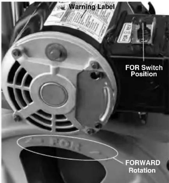
text_image
Warning Label FOR Switch Position FOR FORWARD RotationFigure 8 – Proper Drum Rotation (FOR Switch Position)
Machine and Work Area Set-Up
WARNING


Set up the drain cleaning machine and work area according to these procedures ^5 to reduce the risk of injury from electric shock, fire, machine tipping, twisted or broken cables, chemical burns, infections and other causes, and prevent drain ^6 cleaner damage.
Always wear safety glasses, and other appropriate protective equipment when setting up your drain cleaner.
-
Check work area for:
-
Adequate lighting.
- Flammable liquids, vapors or dust that may ignite. If present, do not work in area until sources have been identified
and corrected. The drain cleaner is not explosion proof and can cause sparks.
- Clear, level, stable dry place for machine and operator. Do not use the machine while standing in water. If needed, remove the water from the work area.
- Properly grounded electrical outlet of the correct voltage. Check machine serial plate for required voltage. A three-prong or GFCI outlet may not be properly grounded. If in doubt, have outlet inspected by a licensed electrician.
- Clear path to electrical outlet that does not contain any potential sources of damage for the power cord.
- Clear path to transport the drain cleaner to the work area.
- Inspect the drain to be cleaned. If possible, determine the access point(s) to the drain, the size(s) and length(s) of the drain, distance to tanks or mainlines, the nature of the blockage, presence of drain cleaning chemicals or other chemicals, etc. If chemicals are present in the drain, it is important to understand the specific safety measures required to work around those chemicals. Contact the chemical manufacturer for required information.
If needed, remove fixture (water closet, etc.) to allow access to the drain. Do not feed the cable through a fixture. This could damage the drain cleaner and the fixture.
- Determine the correct equipment for the application. See Specifications.
Drain cleaners for other applications can be found by consulting the RIDGID Cata - log, on line at RIDGID.com
- Make sure machine has been properly inspected.
If needed, place protective covers in the work area. The drain cleaning process can be messy.
Take the drain cleaning machine to the work area along the clear path. Before moving the machine, make sure that the handle is locked into the up position for transport (see Figure 9). If the machine needs to be lifted, use proper lifting techniques. Use care moving equipment up and down stairs, and be aware of possible slip hazards. Wear appropriate footwear to help prevent slips.

text_image
Handle Lock RIDGID HandleFigure 9 – Handle Operation
- Position the drain cleaning machine so that the K-400 cable outlet is within 2 feet (0.6m) of the drain access. Greater distances from the drain access increases the risk of the cable twisting or kinking. If the machine cannot be placed with the drum opening within 2' (0.6m) of the drain access, extend the drain access back to within 2' (0.6m) of the cable outlet with similar sized pipe and fittings. Improper cable support can allow the cable to kink and twist and can damage the cable or injure the operator. (See Figure 10.) If using front guide hose, place machine so that at least 6" (150mm) of guide hose can be placed in drain opening.

natural_image
Man in work uniform operating a small industrial machine in a workshop (no visible text or symbols)Figure 10 – Example of Extending Drain to within 2' (0.6m) of Cable Outlet
- Evaluate the work area and determine if any barriers are needed to keep by-
standers away from the drain cleaner and work area. The drain cleaning process can be messy and bystanders can distract the operator.
- Select proper tool for the conditions. If the nature of the obstruction is unknown, it is good practice to use a straight or bulb auger to explore the obstruction and retrieve a piece of the obstruction for inspection.
Once the nature of the obstruction is known, an appropriate tool can be selected for the application. A good rule of thumb is to start by running the smallest available tool through the blockage to allow the backed up water to start flowing and carry away the debris and cuttings as the drain is cleaned. Once the drain is open and flowing, other tools appropriate for the blockage can be used. Generally, the largest tool used should be no bigger than the inside diameter of the drain minus one inch.
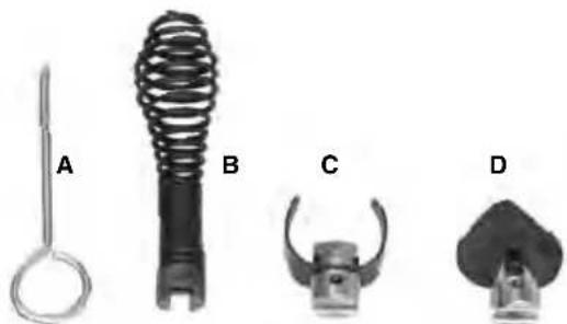
natural_image
Four labeled mechanical components (A, B, C, D) shown in grayscale, including spring, clamp, and pin-like features (no text or symbols beyond labels)Figure 11 – Tools Supplied With K-400
The K-400 is supplied with these tools (Figure 11).
A.Cable Pin Key
B. The T-202 Bulb Auger – for exploration of the clog and pulling out stoppages such as hair, etc.
C. The T-205 "C" Cutter – for use in grease blockages and cleaning the walls of the pipe.
D. The T-211 Spade Cutter – for use after an auger and to open up floor drains.
Proper tool selection depends on the specific circumstances of each job and is left to the users' judgement.
A variety of other cable attachments are available and are listed in the Optional Equipment section of this manual. Other information on cable attachments can be found in the RIDGID Catalog and on line at RIDGID.com.
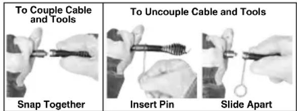
Figure 12 – Connecting/Disconnecting Tools
-
Securely install the tool to the end of the cable. The T-slot coupler allows the cutting tool to be slid onto the cable coupler. Make sure that the spring-loaded plunger in the cable coupler moves freely and retains the tool. If the pin sticks in the retracted position, the cutting tool may fall or in use. To remove cutting tool, insert the pin key into the hole in the coupling to depress the plunger and slide the coupling apart (see Figure 12).
-
Position the foot switch for easy accessibility. You must be able to hold and control the cable, control the foot switch, and reach the FOR/OFF/REV switch.
- Confirm that the FOR/OFF/REV switch is in the OFF position.
-
Run the cord along the clear path. With dry hands plug the drain cleaner into a properly grounded outlet. Keep all connections dry and off the ground. If the power cord is not long enough, use an extension cord that:
-
Is in good condition
- Has a three prong plug like on the Drain Cleaner.
- Is rated for outdoor use and contains a W or W-A in the cord designation (i.e. SOW).
- Has sufficient wire size. For extension cords up to 50' (15,2 m) long use 16 AWG (1,5 mm ^2 ) or heavier. For extension cords 50'-100' (15,2 m – 30,5 m) long use 14 AWG (2,5 mm ^2 ) or heavier.
When using an extension cord, the GFCI on the drain cleaner does not protect the extension cord. If the outlet is not GFCI protected, it is advisable to use a plug in type GFCI between the outlet and the extension cord to reduce the risk of shock if there is a fault in the extension cord.
Operating Instructions
WARNING

natural_image
Three black-and-white icons: a circular saw, a hand holding a gear, and a person running with a stick (no text or symbols)Always wear eye protection to protect your eyes against dirt and other foreign objects.
Only wear RIDGID drain cleaning gloves or mitts ("gloves"). Never grasp the rotating cable with anything else, including a glove or a rag. They can become wrapped around the cable, causing hand injuries. Only wear latex or rubber gloves under RIDGID drain cleaner gloves. Do not use damaged drain cleaning gloves.
Always use appropriate personal protective equipment while handling and using drain cleaning equipment. Drains may contain chemicals, bacteria and other substances that may be toxic, infectious, cause burns or other issues. Appropriate personal protective equipment always includes safety glasses and RIDGID drain cleaning gloves, and may include equipment such as latex or rubber gloves, face shields, goggles, protective clothing, respirators and steel-toed footwear.
Do not allow the cutter to stop turning while the machine is running. This can overstress the cable and may cause twisting, kinking or breaking of the cable. Twisting, kinking or breaking cable may cause striking or crushing injuries.
Keep gloved hand on the cable whenever the machine is running. This provides better control of the cable and helps prevent twisting, kinking and breaking of the cable. Twisting, kinking or breaking cable may cause striking or crushing injuries.
Position machine within two feet (0.6m) of the drain inlet or properly support exposed cable when the distance exceeds two feet. Greater distances can cause control problems leading to twisting, kinking or breaking of the cable. Twist - ing, kinking or breaking cable may cause striking or crushing injuries.
One person must control both the cable and the foot switch. If the cutter stops rotating, the operator must be able to turn the machine motor off to prevent twisting, kinking and breaking of the cable. Twisting, kinking or breaking cable may cause striking or crushing injuries.
Follow operating instructions to reduce the risk of injury from twisted or broken cables, cable ends whipping around, machine tipping, chemical burns, in fec tions and other causes.
-
Make sure that the machine and work area is properly set up and the work area is free of bystanders and other distractions.
-
Pull cable out of drum and feed into drain. Push cable as far into drain as it will go. At least one foot (.3 m) of cable must be in drain so that the end of the cable will not come out of the drain and whip around when the machine is started.
Directly route the cable from the outlet of the machine to the drain opening, minimizing exposed cable and changes in direction. Do not tightly bend the cable – this can increase the risk of twisting or breaking.
- Assume a proper operating position.
- Be sure you can control the ON/OFF action of the foot switch and can quickly release the foot switch if needed. Do not step on foot switch yet.
- Be sure that you have good balance, do not have to over reach, and cannot fall on the foot switch, drain cleaning machine, the drain or other hazards.
- You must be able to place at least one hand on the cable at all times to control and support the cable.
- You must be able to reach the FOR/ - OFF/ REV switch.
This operating position will help to maintain control of the cable and machine. (See Figure 13.)
- Move the FOR/OFF/REV switch to the FOR (FORWARD) position. Do not depress the foot switch yet. FOR/OFF-/REV refers to the drum/cable rotation and not to the direction of cable movement. Do not rotate the cable in reverse except as specifically described in these instructions. Running the drain cleaner in REV (REVERSE) can damage the cable.
natural_image
Man kneeling beside a small industrial machine in a workshop (no visible text or symbols)Figure 13 – In Operating Position, Manually Feeding Cable
Operation
The K-400 Drain Cleaning Machine is available in two different feed configurations, either manual feed or AUTO FEED. A K-400 supplied with the AUTOFEED can either feed the cable with the AUTOFEED or by manually pulling the /cable from the drum and feeding it into the drain. With the AUTOFEED you can switch back and forth between operating methods has needed. If an AUTOFEED is not available, the K-400 can only be used manually.
Feeding the Cable into the Drain
Manual Operation
-
Confirm that at least one foot (0,3 m) of cable is in the drain.
-
Grasp the exposed cable with both gloved hands equally spaced and pull 6"-12" (150mm - 300mm) of cable out of the drum so that there is a slight bow in the cable. Gloved hands must be on the cable to control and support the cable. Improper cable support can allow the cable to kink or twist and can damage the cable or injure the operator. Make sure that the cable outlet of the drain cleaner is within 2' (0.6m) of the drain opening (Fig ure 13.).
-
Depress the foot switch to start the machine. The person controlling the cable must also control the foot switch. Do not operate the drain cleaner with one person controlling the cable and another person controlling the foot switch. This can lead to twisting, kinking and breaking of the cable.
-
Feed the rotating cable into the drain. The rotating cable will work its way into
the drain as you push on the cable with gloved hands. Do not allow the cable to build up outside the drain, bow or curve. This can allow the cable to twist, kink or break.
- When the cable has been fed into the drain opening, pull 6"-12" (0.15 - 0.3m) more cable from the drum and continue feeding the rotating cable into the drain.
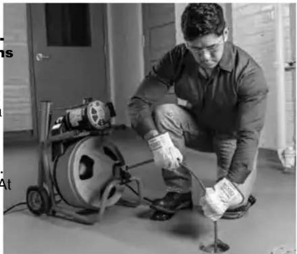
AUTOFEED Cable Feed Operation
- Confirm that at least one foot (0.3m) of cable is in the drain.
- Grasp near the center of the exposed length of cable with a gloved hand. Gloved hand must be on the cable to control and support the cable. Improper cable support can allow the cable to kink or twist and can damage the cable or injure the operator. Make sure that the cable outlet of the drain cleaner is within 2' (0.6m) of the drain opening. Place the other hand on the cable feed handle. Handle should be in neutral (Vertical) position (see Figure 14).
See "Using Machine with a Front Guide Hose" if using a guide hose.
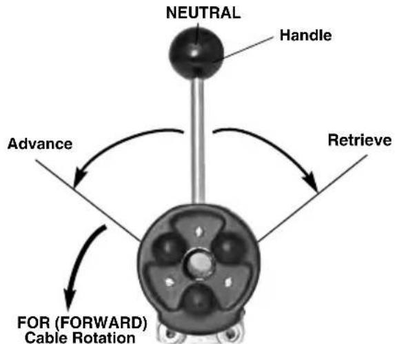
flowchart
graph TD
    A["NEUTRAL"] --> B["Handle"]
    B --> C["FOR (FORWARD) Cable Rotation"]
    C --> D["Advance"]
    D --> E["Retrieve"]
    E --> A
Figure 14 – AUTOFEED Cable Feed Directions (Viewed From Front of Machine)
-
Depress the foot switch to start the machine. The person controlling the cable must also control the foot switch. Do not operate the drain cleaner with one person controlling the cable and another person controlling the foot switch. This can lead to twisting, kinking and breaking of the cable
-
With the cable rotating in the FOR (FOR-WARD) direction, move the AUTOFEED control handle to the ADVANCE position until it engages and advances the cable. ADVANCE (or RETRIEVE) can be al-
most 90° from the NEUTRAL position (Figure 14). The rotating cable will work into the drain as you control the cable with your gloved hand. Do not allow the cable to build up outside the drain, bow or curve. This can allow the cable to twist, kink or break.

natural_image
Person cleaning a tiled floor with a pump and bag (no visible text or symbols)Figure 15 – Operating K-400 with AUTOFEED
Passing Through Traps or Other Transitions
If it is difficult to get the cable through a trap or other fitting, the following methods or combinations of methods can be used.
- Sharp thrusts of the cable, both with and without the cable rotating, can help the cable through a trap.
- In some cases with the switch in the OFF position, rotating the drum by hand can change the orientation of the cutter to allow it to more easily negotiate the fitting.
- Run the drain cleaner in REV rotation for se veral seconds while pushing on the cable. Only do this long enough to get the cable started through the trap. Running the cable in reverse can damage the cable.
- Attach a single section (only one section) of C-9 cable as a flexible leader between the end of the cable and the tool.
If these options do not work, consider using a smaller diameter or more flexible cable, or a different drain cleaner.
Cleaning the Drain
As you feed the cable into the drain, you may see the cable slow down or build up outside the drain. Always keep your hands on the cable. You may feel the cable start to wind or load up (this may feel like the cable is starting to twist or squirm). This may be a transition in the drain (trap, elbow, etc.), build up in the
drain (grease, etc.) or the actual blockage. Feed the cable slowly and carefully. Do not le cable build up outside the drain. This can cause the cable to twist, kink or break.
Pay attention to the amount of cable that has been fed into the drain. Feeding cable into a larger drain, septic tank or similar transition may cause the cable to kink or knot and prevent removal from the drain. Minimize the amount of cable fed into the transition to prevent problems. Each wrap of the cable in the drum is approximately 3.5' (1.1 m).
Working the Blockage
If the end of the cable stops turning, it is no longer cleaning the drain. If the end of the cable becomes lodged in the blockage and power is maintained to the drain cleaner, the cable will start to wind up (this may feel like the cable is starting to twist or squirm). Having a hand on the cable allows you to feel this wind up and control the cable.
If the cable end stops turning or if the cable starts to wind up, immediately pull the cable back from the obstruction.
- Manual Operation – Pull back on the cable to free the cable end from the blockage.
- AUTOFEED cable feed operation – Move the handle to the retrieve position (Figure 14) to free the cable end from the blockage
Do not keep the cable rotating if the cable is stuck in a blockage. If the cable end stops turning and the drum keeps rotating, the cable can twist, kink or break.
Once the cable end is free of the blockage and turning again, you can slowly feed the cable end back into the blockage. Do not try to force the cable end through the blockage. Let the spinning end "dwell" in the blockage to completely break it up. Manual operation may give the best control in these instances. Work the tool in this manner until you have moved completely past the blockage (or blockages) and the drain is flowing.
While working the blockage, the tool and cable may become clogged with debris and cuttings from the blockage. This can prevent further progress. The cable and tool need to be retrieved from the drain and the debris removed. See section on "Retrieving the Cable".
Handling a Stuck Tool
If the tool stops turning and the cable cannot be pulled back from the blockage, release the foot switch while firmly holding the cable. If using cable feed, release the handle to come back to the neutral (straight up) position. Do not remove hands from cable or cable may kink, twist and break. The motor will stop and the cable and drum may turn backwards until the energy stored in the cable is relieved. Do not remove hands from cable until the tension is released. Place FOR/OFF/REV switch in OFF position.
The torque limiter helps to prevent cable damage from cable flip over in the drum by stopping drum and cable rotation when the torque exceeds the setting. The motor will continue to rotate as long as the foot switch is pressed, but the drum and cable will stop rotating when the torque limiter setting is exceeded. The torque limiter cannot prevent all cable damage in the drum, and cannot prevent cable flip over outside the drum. If the drum stops turning, the cable and tool also are not turning.
Freeing a Stuck Tool
If the tool is stuck in the blockage, with the FOR/OFF/REV switch in the OFF position and the foot switch released, try pulling the cable loose from the blockage. If the tool will not come free from the blockage, place the FOR/OFF/REV switch in the REV position. Grasp the cable with both gloved hands, press the foot switch for several seconds and pull on the cable until it is free of the blockage. Do not operate the machine in the REV position any longer than required to free the cutting tool from the blockage or cable damage can occur. Place the FOR/OFF/REV switch in the FOR position and continue cleaning the drain.
Retrieving the Cable
-
Once the drain is open, if possible start a flow of water down the drain to flush the debris out of the line and help clean the cable as it is retrieved. This can be done by running a hose down the drain opening, turning on a faucet in the system or other methods. Pay attention to the water level, as the drain could plug again.
-
The FOR/OFF/REV switch should be in the FOR position – do not retrieve the cable with the switch in the REV position, this can damage the cable. As with feeding the cable into the drain, cables can be caught while being retrieved.
- Manual Operation – With both gloved hands equally spaced on the exposed cable for control, pull 6"-12" (0.15 - 0.3m)
lengths of cable from the drain at a time and feed it into the drum. Con tinue re-trieving cable until the cable end is just inside the drain opening.
- AUTOFEED Cable Feed Operation – With one hand near the center of the exposed length of cable, move the handle to the RETRIEVE position to retrieve the cable. The rotating cable will work its way out of the drain and back into the drum. Continue retrieving cable until the cable end is just inside the drain opening. Release the handle to come back to the neutral position.
-
Release the foot switch, allowing the drum to come to a complete stop. Do not pull the end of the cable from the drain while the cable is rotating. The cable can whip around and cause serious injury. Pay attention to the cable during retrieval as the cable end can still become stuck.
-
Place the FOR/OFF/REV in the OFF position. Pull the remaining cable from the drain with gloved hands and feed into the drain cleaner. If needed, change the tool and continue cleaning following the above process. Several passes through a line are recommended for complete cleaning.
Using Machine with a Front Guide Hose
The front guide hose is an optional accessory to help protect fixtures and contain the liquid and debris thrown off of the cable. It can only be used with an AUTOFEED cable feed. Using the Front Guide hose can decrease feedback from the cable, making it harder to tell what conditions the cable is encountering. This may increase the possibility of damage to the cable. Using the front guide hose makes it more difficult to switch back and forth between manual and cable feed operation.
Using a machine with the front guide hose is similar to using a machine with the AUTO-FEED cable feed. Follow instructions with the following exceptions:
- When setting up the machine, insert the guide hose at least 6" into the drain.
- Instead of holding the cable, hold the guide hose. See Figure 16. Always control the guide hose and properly support the cable to prevent the cable from twisting, kinking or breaking.

natural_image
Man working on a large industrial machine with tools, placed on tiled floor (no visible text or symbols)Figure 16 – Using Machine with Guide Hose
When using a front guide hose, pay attention how the guide hose feels in your hand and watch the drum rotation. Because the guide hose is over the cable, there is less sensitivity to the loading of the cable, and it is harder to tell if the tool is rotating or not. If the tool is not rotating, the drain is not being cleaned.
If the tool continues to get hung up in the blockage, stop using the AUTOFEED cable feed (leave the handle in the neutral position) and work the cable manually. To do this, the cable must be retrieved from the drain and the guide hose removed to allow proper positioning of the machine to the drain and access to the cable. Do not try to work the cable by hand with the front guide hose in place.
When retrieving the cable, be sure to stop the cable before the tool is pulled into the end of the guide hose to prevent damage.
Maintenance Instructions
WARNING
FOR/OFF/REV switch should be OFF and machine unplugged before performing any maintenance.
Always wear safety glasses and other appropriate protective equipment when performing any maintenance.
^3 Cleaning
The machine should be cleaned as needed with hot, soapy water and/or disinfectants. Do not allow water to enter motor or other electrical components. Make sure unit is completely dry before plugging in and using.
Cables
Cables should be thoroughly flushed with water after every use to prevent damaging effects of sediment and drain cleaning compounds. Fluss cable with water and drain debris from drum by tipping machine forward after every use to remove sediment, etc. which can corrode cable.
Cable connector plunger pin can be lubricated with light machine oil.
AUTOFEED Cable Feed
After each use, hose out AUTOFEED cable feed assem bly with water and lubricate with lightweight machine oil.
Lubrication
In general, the drain cleaner will not require lubrication. If the drum is removed or changed, grease the bearings with good general purpose grease.
Front Guide Hose
After use, flush the guide hose with water and drain.
Belt Removal/Installation
- Loosen belt guard screws (near motor) and slide guard off screws. Do not operate drain cleaner with belt guard removed.
- Hold the belt tensioner to the side and remove the belt from the drum and pulley. (See Figure 17.) Slide the belt to the front of the machine near the front bearing mount.
- Remove the bolts and nuts holding the front bearing mount and AUTOFEED cable feed (see Figure 5) in place. Pull the drum and front bearing mount forward enough to slide the belt off the machine, between the front bearing mount and the frame.
- Reverse procedure to replace belt. If changing belt, adjust torque limiter as described below.
Torque Limiter Adjustment
The K-400 Drain Cleaner is equipped with a torque limiter to help prevent cable damage from flip over in the drum.
The torque limiter causes the belt to slip when the torque exceeds a set value. The torque limiter is set at the factory, and in most cases will never need to be adjusted. If excessive belt slippage is experienced during use, this procedure can be used to check and adjust the torque limiter setting. Additionally, if the belt is changed, the torque limiter will need to be checked and adjusted.
NOTICE Do not adjust the torque limiter outside of the specified range. Setting the torque limiter outside of the specified range could result in damage to the machine and cable.
- Loosen belt guard screws (near motor) and slide guard off screws.
- Check the gap between the torque limiter spring coils near the middle of the spring. (See Figure 17.) This can be measured with a set of feeler gauges.
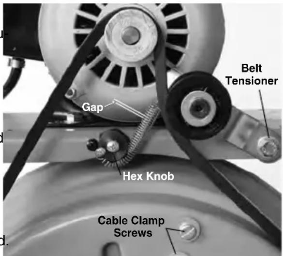
text_image
Belt Tensioner Gap Hex Knob Cable Clamp ScrewsFigure 17 – Torque Limiter Adjustment. (Shown With Belt Guard Removed)
- The torque limiter is properly set if the gap is 0.048" (1.22 mm) to 0.060" (1.52 mm), about the thickness of a U.S. dime. If the gap is within this range, the torque limiter is properly set and no adjustment is necessary.
- If torque limiter is outside of acceptable range, the torque limiter must be adjusted.
- Loosen screw located in the center of hex knob approximately 3 turns.
- Pull the hex knob out slightly. If the gap needs to be increased, rotate the knob clockwise to the next flat of the hex knob. If the gap needs to be decreased, rotate counter-clockwise to the next flat of the hex knob.
-
Repeat steps 2-5 until the spring coil gap is correct.
-
Tighten the hex knob screw.
-
Replace the guard. Do not operate drain cleaner with belt guard removed.
Replacing Cable
To Remove Cable From Drum
- Pull out excess cable from drum allowing access to cable bracket.
- Loosen screws on back of drum that fasten cable clamps (Figure 17) and back plate against back wall of drum.
- Pull end of old cable from drum and discard.
To Install Replacement Cable
-
To make cable installation easier, completely uncoil new cable before proceeding. Use caution when removing the cable from the package. The cable is under tension and could strike the user. Adding a 3 degree bend about 4" (100mm) from the drum end of cable will facilitate it entering the drum.
-
Insert about 24" (0.8m) of cable through the guide tube into the drum. Cable should coil into the drum in a count e clockwise direction (Figure 18).
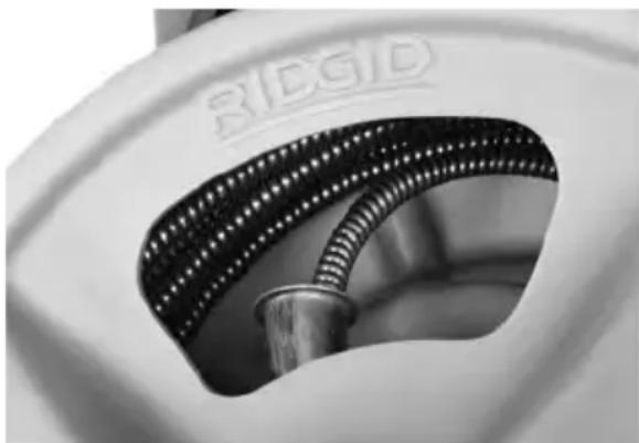
natural_image
Close-up of a white mechanical component with a metallic cylindrical part inserted, showing internal mesh structure (no text or symbols visible)Figure 18 – Coil Cable Into Drum As Shown
-
Reach inside the drum and maneuver end of cable so that it is between the cable clamp and back plate. The end of the cable should extend at least 3" (75mm) past the clamp.
-
Retighten the screws to clamp the cable against the back plate and back wall of the drum.
-
Feed cable into drum.
Optional Equipment
WARNING
To reduce the risk of serious injury, only use optional equipment specifically designed and recommended for use with the RIDGID K-400 Drain Cleaning Machine, such as those listed.
IW (Integral Wound) Solid Core Cables
| Catalog No. | Model Description | Weight lb kg | |||
| ^1/_2^ 10mm | 87577 C31IW 50 | (15m) IW Cable18 | 8.2 | ||
| 87582 C32IW 75 | (23m) IW Cable26 | 11.8 | |||
| 87587 C33IW 100 | (30m) IW Cable34 | 15.4 | |||
| 91037— | Repair End for ^1/_2^ IW Cable 0.5 | 0.2 | |||
| ^1/_2^ 12mm | 87592 C44IW 50 | (15m) IW Cable27 | 12.2 | ||
| 87597 C45IW 75 | (23m) IW Cable39 | 17.7 | |||
| 91042— | Repair End for ^1/_2^ IW Cable 0.6 | 0.3 | |||
| Catalog No. No. | Model Weight Description lb. kg | ||||
| 41937 | — | RIDGID Drain Cleaning Gloves, Leather | ^1/_2 | 0.2 | |
| 70032 | — | RIDGID Drain Cleaning Gloves, PVC | |||
| 59230 | A-13 | Pin Key For ^3N^* Cable | — | — | |
| 26773 | — | K-400 AUTOFEED Assembly | 3.14 | 1.42 | |
| 26778 | — | Guide Hose | 21 | ||
Tools and Replacement Blades – Fits 38 " and 12 " Cables Fits C-31IW, C-32IW, C-33IW, C-44IW and C-45IW
| Catalog No. | Model No. | Description | Replacement Blade(s) | |
| 62995 | T-202 | Bulb Auger, 1 ^1 / ^4 O.D. | — | |
| 63065 | T-217 | Drop Head, 4" Long | — | |
| 63005 | T-205 | “C” Cutter 1 ^3 / ^4 " | 97835 | |
| 63010 | T-206 | Funnel Auger, 3" Long | — | |
| 63035 | T-211 | Spade Cutter, 1 ^3 / ^4 " | 97825 | |
| 49002 | T-260 | Tool Set (3/8"- K-400)– T-202 Bulb Auger– T-205 “C” Cutter– T-211 Spade Cutter– A-13 Pin Key | — |
For a complete listing of RIDGID optional e-quip ment available for this tool, see the RIDGID Catalog online at RIDGID.com or call Ridge Tool Technical Service Depart ment (800) 519-3456.
Machine Storage
WARNING The drain cleaner and cables must be kept dry and indoors or well covered if kept outdoors. Store the machine in a locked area that is out of reach of children and people unfamiliar with drain cleaners. This machine can cause serious injury in the hands of un-trained users.
Service and Repair
WARNING
Improper service or repair can make attachments unsafe to operate.
The "Maintenance Instructions" will take care of most of the service needs of this machine. Any problems not addressed by this section
should only be handled by an authorized RIDGID service technician.
Tool should be taken to a RIDGID Authorized Inde pend ent Service Center or returned to the factory. Only use RIDGID service parts.
For information on your nearest RIDGID Authorized In depen dent Service Center or any service or repair questions:
- Contact your local RIDGID distributor.
- Visit RIDGID.com to find your local RIDGID contact point.
- Contact Ridge Tool Technical Service Department at rtctechservices@emerson.com, or in the U.S. and Canada call (800) 519-3456.
Disposal
Parts of the K-400 Drain Cleaning Machine contain valuable materials and can be recycled. There are companies that specialize in recycling that may be found locally. Dispose of the components and any waste oil in compliance with all applicable regulations. Contact your local waste management authority for more information.
For EC Countries: Do not dispose of electrical equipment with household waste!
According to the European Guide - line 2012/ 19/ EU for Waste Electri cal and Electronic Equip ment and its
implementation into national legislation, electrical equipment that is no longer usable must be collected separately and disposed of in an environmentally correct manner.
Troubleshooting
| PROBLEM POSSIBLE REASON SOLUTION | ||
| Cable kinking or breaking. | Cable is being forced. | Do Not Force Cable! Let the cutter of the work. |
| Cable used in incorrect pipe diameter. | Use correct cable for pipe. | |
| Motor switched to reverse. | Use reverse only if cable gets caught in pipe. | |
| Cable exposed to acid. | Clean and oil cables routinely. | |
| Cable worn out. | If cable is worn, replace it. | |
| Cable not properly supported. | Support cable properly, see instructions. | |
| Torque limiter not properly adjusted. | Properly adjust torque limiter. | |
| Drum stops while foot switch is depressed. Re starts when foot switch is re-depressed. | Hole in foot switch or hose. | Replace damaged component. |
| Hole in air switch. | If no problem found with pedal or hose, replace air switch. | |
| Drum turns in one direction but not the other. | Faulty FOR/OFF/REV switch. | Replace switch. |
| Ground Fault Circuit In ter rupter trips when ma chine is plugged in or when foot pedal is depressed. | Damaged power cord. | Replace cord set. |
| Short circuit in motor. | Take motor to your nearest Service Center. | |
| Faulty Ground Fault Circuit Interrupter. | Replace cord set that includes a Ground Fault Circuit Interrupter. | |
| Moisture in motor, switch box or on plug. | Take drain cleaner to your nearest Service Center. | |
| Motor turning but drum is not. | Torque limiter slipping because improperly adjusted. | Properly adjust torque limiter. |
| Torque limiter slipping because cable is being forced. | Do not force cable. | |
| Belt not on drum or pulley. | Re-install belt. | |
| AUTOFEED cable feed doesn't work. | Cable feed full of debris. | Clean cable feed. |
| Cable feed needs lubrication. | Lubricate Cable feed. | |
| Machine wobbles or moves while cleaning drain. | Cable not evenly distributed. | Pull all cable out and feed again, evenly distribute. |
| Ground not level. | Place on level stable surface. | |
natural_image
Industrial electric pump with motor and wheels (no visible text or symbols)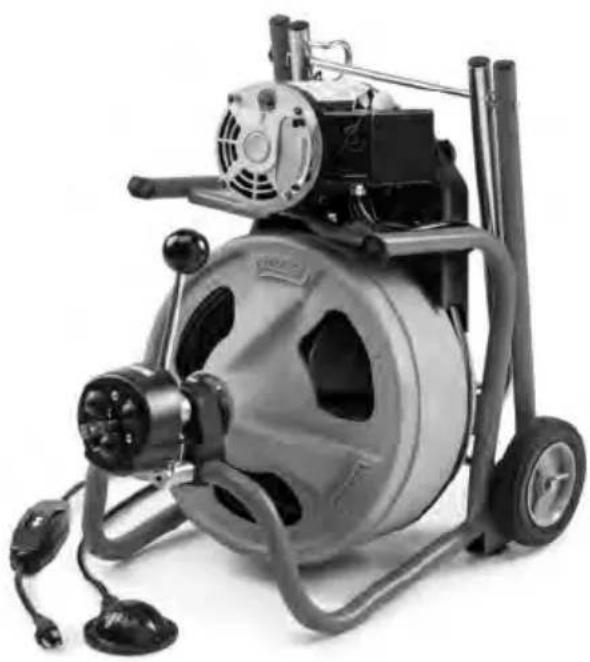
natural_image
Exterior view of a portable electric vacuum cleaner with attached fan and wheels (no visible text or symbols)
AVERTISSEMENT
text_image
RIDGE Tool Company, Elyria, Ohio, U.S.A. RIDGID.com Model No. Serial No. XXXXXXXMMYY Hz W V ~ A n₀ /min Duty NOM-EM Intertek c Interteknatural_image
Three different types of industrial gloves, one with a white gauze and the other with black rubber gloves (no visible text or symbols)natural_image
Man kneeling beside a small industrial machine in a workshop (no visible text or symbols)natural_image
Four labeled mechanical components (A, B, C, D) shown in different orientations, no text or symbols present.natural_image
Man kneeling beside a small industrial machine in a workshop (no visible text or symbols)natural_image
Person cleaning a tiled floor with a pump and tool (no visible text or symbols)natural_image
Man kneeling beside a large industrial vacuum cleaner in a tiled room (no visible text or symbols)natural_image
Close-up of a mechanical component with textured surface and metallic shaft (no visible text or symbols)natural_image
Industrial electric pump with motor and wheels (no visible text or symbols)
natural_image
Exterior view of a portable electric vacuum cleaner with control panel and wheels (no visible text or symbols)
ADVERTENCIA
text_image
RIDGE Tool Company, Elyria, Ohio, U.S.A. RIDGID.com Model No. Serial No. XXXXXXXXX MMYY Hz W V ~ A /no /min Duty NOM-CEI Intertek Interteknatural_image
Three black-and-white pictograms showing mechanical devices and tools (no text or symbols)natural_image
Three different types of industrial gloves shown side by side, no visible text or symbols on the gloves themselves.natural_image
Man in work uniform operating a large industrial machine in a workshop (no visible text or symbols)natural_image
Man in safety gear using a power pump and mixing equipment in a workshop (no visible text or symbols)natural_image
Person operating a water pump on tiled floor, no visible text or symbolsnatural_image
Mechanic working on a large industrial machine in a tiled room (no visible text or symbols)natural_image
Close-up of a mechanical component with threaded end and cylindrical shaft (no visible text or symbols)RIDGID® K-400 Drain Cleaning Machines
RIDGE TOOL COMPANY Ridge Tool Europe NV (RIDGID)
EC DECLARATION OF CONFORMITY
DÉCLARATION DE CONFORMITÉ CE
DEKLARACJA ZGODNOŚCI WE
IEC 62841-1, IEC 62841-3-14

Signature: Krondorfer Name: Harald Krondorfer Qualification: V.P. Engineering Date: 03/01/2020

50111050
Conforms to UL 62841-1/UL Std. 62841-3-14
Certified to CSA C22.2#62841-1/CSA Std. C22#62841-3-14
What is covered
RIDGID ^® tools are warranted to be free of defects in workmanship and material.
How long coverage lasts
This warranty lasts for the lifetime of the RIDGID® tool. Warranty coverage ends when the product becomes unusable for reasons other than defects in workmanship or material.
How you can get service
To obtain the benefit of this warranty, deliver via prepaid transportation the complete product to RIDGE TOOL COMPANY, Elyria, Ohio, or any RIDGID® AUTHORIZED INDEPENDENT SERVICE CENTER. Pipe wrenches and other hand tools should be returned to the place of purchase.
What we will do to correct problems
Warranted products will be repaired or replaced, at RIDGE TOOL'S option, and returned at no charge; or, if after three attempts to repair or replace during the warranty period the product is still defective, you can elect to receive a full refund of your purchase price.
What is not covered
Failures due to misuse, abuse or normal wear and tear are not covered by this warranty. RIDGE TOOL shall not be responsible for any incidental or consequential damages.
How local law relates to the warranty
Some states do not allow the exclusion or limitation of incidental or consequential damages so the above limitation or exclusion may not apply to you. This warranty gives you specific rights, and you may also have other rights, which vary, from state to state, province to province, or country to country.
No other express warranty applies
This FULL LIFETIME WARRANTY is the sole and exclusive warranty for RIDGE PRODUCTS. No employee, agent, dealer, or other person is authorized to alter this warranty or make any other warranty on behalf of the RIDGE TOOL COMPANY.

text_image
RIDGID FULL LIFETIME WARRANTY Against Material Defects & WorkmanshipParts are available online at Store.RIDGID.com
Ridge Tool Company
400 Clark Street
Elyria, Ohio 44035-6001
U.S.A.