
CentraClean 15301 - Vacuum Cleaner THOMAS - Free user manual and instructions
Find the device manual for free CentraClean 15301 THOMAS in PDF.
| Brand | Thomas |
| Model | CentraClean 15301 |
| Category | Central vacuum cleaner |
| Power supply | 230 V ~ 16 A |
| Control type | Radio (range up to 16 transmitters), pilot wire or switch on the device |
| Filtration system | Long-life filter cartridge, cyclone principle |
| Dust container capacity | Not specified (removable waste bin) |
| Compatible hose(s) | Comfort, ComfortDeluxe, Premium |
| Variable power (PowerControl) | 70% (max) and 40% (min) of maximum power |
| Automatic safety shut-off | After 15 minutes of continuous operation |
| Thermal protection | Shut-down in case of motor overheating |
| Remote control batteries | Alkaline manganese battery (respect polarity) |
| Filter maintenance | Cleaning or replacement every 6 months or after 25 hours of operation |
| Authorized use | Household, dry dust vacuuming (do not vacuum liquids, ashes, flammable substances) |
| Installation | Wall mounting with bracket, connection of suction pipes (DN 50) and purge pipes (DN 70) |
| Ambient temperature | Protect from weather, humidity and heat sources |
| Weight (estimate) | Approximately 12 kg (central unit) |
| Dimensions (L × W × H) | Not specified |
| Spare parts and repairability | Original parts, repair by authorized after-sales service |
Frequently Asked Questions - CentraClean 15301 THOMAS
User questions about CentraClean 15301 THOMAS
0 question about this device. Answer the ones you know or ask your own.
Ask a new question about this device
Download the instructions for your Vacuum Cleaner in PDF format for free! Find your manual CentraClean 15301 - THOMAS and take your electronic device back in hand. On this page are published all the documents necessary for the use of your device. CentraClean 15301 by THOMAS.
USER MANUAL CentraClean 15301 THOMAS
INSTALLATION INSTRUCTIONS AND DIRECTIONS FOR USE
INSTRUCTIONS D'INSTALLATION ET DE SERVICE
INSTALLATIEVOORSCHRIFT/HANDLEIDING
natural_image
Illustration of a hand holding a device with a circular icon and a separate view showing its internal components (no text or symbols present)natural_image
Illustration of hands holding a device with a circular button and sensor icons (no text or symbols)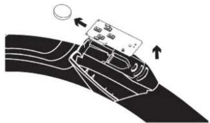
natural_image
Diagram of a car interior with a device on the roof and directional arrows indicating movement (no text or symbols)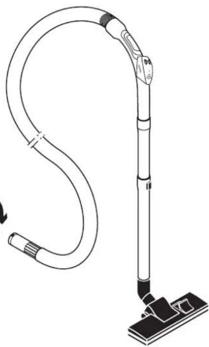
natural_image
Line drawing of a vacuum cleaner with attached hose and base mount (no text or symbols)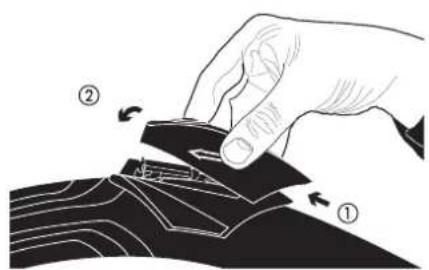
Batteriedaten:

4.2.2 Saugschlauch-Comfort
Hinweis:
natural_image
Technical line drawing of a mechanical device showing internal components and assembly (no text or symbols)Thank you for the confidence you have placed in us. You have made a good choice because the THOMAS central vacuum systems opens up new vistas in vacuum cleaning:
- No lugging the heavy vacuum cleaner from room to room,
- No exhaust air escapes into the room where you are cleaning, which is particularly beneficial not only for allergy sufferers,
- Without a lot of noise but powerful cleaning,
- No problems when cleaning staircases and surfaces over your head.
Please read and observe the instructions carefully to be able to use this
system efficiently and profit from its application spectrum:
CAUTION!
You must be aware and observe the following instructions which enable you to use the central vacuum system properly according to regulations.
• THOMAS central vacuum system planning handbook
• Installation instructions and directions for use: THOMAS central vacuuming system 15-301 - 18-451 - 34-451.
These are only valid in connection with each other! They are the key to the system and must be kept carefully.
These documents must be handed over to the appropriate future user in the case of change in ownership.
Your THOMAS Team
1. SAFETY REGULATIONS
The system must only be installed and operated in accordance with the planning brochures and the installation instructions and directions for use. Using the system for any other purpose is considered to be improper use and, as a consequence, is not permitted!
We accept and assume no liability in the case of damage caused by faulty installation, operating errors and use of the system for the purpose it was not built for, and non-observance of the safety regulations.
- The hand-held transmitter SKR4TRB2 is only suitable for use with the central vacuum cleaning systems of the following types: 450 ZA; 451 ZA; 15-300 ZA; 18-450 ZA; 34-450 ZA; 15-301 ZA; 18-451 ZA and 34-451 ZA.
Operation of the hand-held transmitter is only permitted in the entire EU and Switzerland, since harmonised frequencies are used (Class 1 equipment)
IMPORTANT!
You must carefully observe the appropriate fire protection regulations more especially when accessing fire protection areas and rooms subject to the location and installation directives as well as the respective valid building ordinance.
The use of the building drainage system for the exhaust air lines is not permitted!
- THOMAS central vacuum systems are only to be used in the home.
- Never put the appliance into operation when:
– the mains cable is damaged,
– any damage is visible.
- The voltage rating given on the type plate must correspond with supply voltage.
- Do not buckle the suction hose! Pay particular attention to the edges of furniture, doors and radiators.
- Never vacuum long or bulky objects. Risk of blockage!
- No liquids or vapour from the kitchen is to be vucuumed by the central vacuum cleaning system.
- Never leave children unattended in the vicinity of electrical appliances and never let your children play around the suction socket.
-
Nozzles and tubes are not to be held close to your head when the appliance is switched on, otherwise there is a risk of injury especially to eyes and ears.
-
The appliance is not suitable for vacuuming health-hazardous, caustic materials and such that contain solutions.
- The appliance must not be operated in rooms in which fire hazardous materials are stored or gases develop.
- This appliance can be used by children who are over 8 years old and by those with reduced physical, sensory or mental capabilities or lacking experience and/or knowledge given that they have been supervised or instructed in the safe use of the appliance and have understood the resulting dangers. Children must not play with the appliance. Cleaning and user maintenance must not be undertaken by children who are not subject to supervision.
- Materials such as petrol, paint thinners and heating oil can give off explosive vapours or mixtures when mixed with the suction air.
- Never vacuum hot ashes or burning objects.
- Check before use to see whether the cartridge filter is fitted properly.
- Never vacuum toner dust or soot! Toner used in printers or copiers, for example, can conduct electricity!
- Acetone, acids and solvents can also dissolve appliances the materials.
- The hose must not be stretched beyond its original length.
- Disconnect the mains plug:
→ it irregularities occur while working,
→ before cleaning of the appliance,
→ every time a filter is changed.
- Never pull the plug out of the electric socket by the cable, always by means of the connection plug.
- Ensure that the connection cable does not come into contact with heat or chemical liquids.
- Never repair damage to the appliance, accessories or the mains cable yourself (special cable required) but always ensure that such damage is repaired by your authorised customer service station because a badly repaired appliance can endanger your health. Make sure that only original spare parts and accessories are used.
- Never expose the appliance to weather. Prevent moisture from getting into the appliance and keep it away from sources of heat.
2. Installation of the central vacuuming system
2.1 Installation of central vacuum cleaner
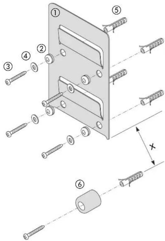
Mounting the unit
- Mount vibration decoupler ② into the wall holder ①.
- Fasten the wall holder with screws ③, washers ④ and dowels ⑤ (height approx. 1.6 m, see planning brochure).
- Fit distance piece ⑥ centric under the wall holder at a distance x.
| Model Distance x | |
| 15-30115-301 PowerControl | 17 cm |
| 18-451 PowerControl 17 cm | |
| 34-451 33 cm | |
- Connect up appliance to power supply, see Point 3.0
- Hang up appliance.
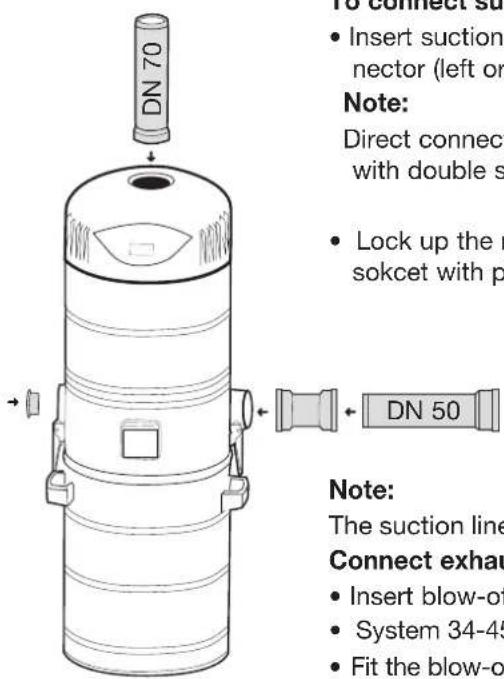
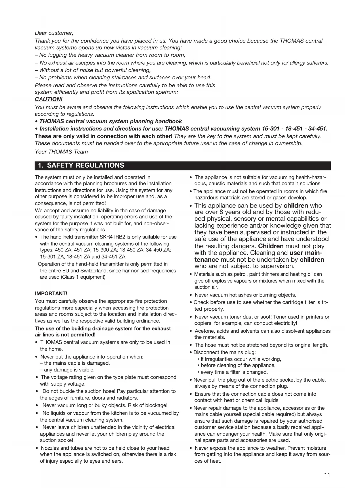
To connect suction line
- Insert suction line (HT-DN 50) to the connector (left or right).
Note:
Direct connection to the vacuum cleaner with double socket (sliding socket).
- Lock up the not needed connection pipe sokcet with plugs (included in delivery).
Note:
The suction lines can be connected up to the left and right where two rising lines are used.
Connect exhaust line
- Insert blow-off line (HT-DN 70) to the exhaust connection.
- System 34-451 must be connected to two exhaust lines (see also planning brochure)
- Fit the blow-off flap on the wall duct allaring the exhaust air to escape, see also planning brochure.
Filter system
All THOMAS central vacuum cleaning systems are equipped with a long-term cartridge filter and in addition operate on a cyclone filter principle.
Assembling cartridge filter
The cartridge filter is prefitted at the factory. Please check that the cartridge filter is firmly fitted before starting to use the cleaner.

Important
Under no circumstances is the system to be operated without cartridge filter or when the cartridge filter is damaged.
The exhaust air system must be connected.
No foreign objects must be allowed to get into the exhaust air system.
3.0 Electrical connections
The system may be operated either by radio, control cable or a combination of radio and control cable. Depending on the required mode of operation, the following steps have to be taken.
3.1 Wireless connection ( = central vacuum unit without power control / central vacuum unit with power control)
3.1.1 General instructions
When operating by radio you can teach-in up to 16 sensors and/or repeaters. Should the 17^th sender be taught in this will lead to the overwriting of the 16^th sender.
Teaching in the sender should be carried out on the floor before the system is mounted.
The LCD display shows the mode of operation and the already previously run working hours as basic display (in new status 000h).
In learn and delete mode the system and status information will also be shown.
By turning off the main switch all activated learn and delete functions are interrupted but can be started again if necessary.
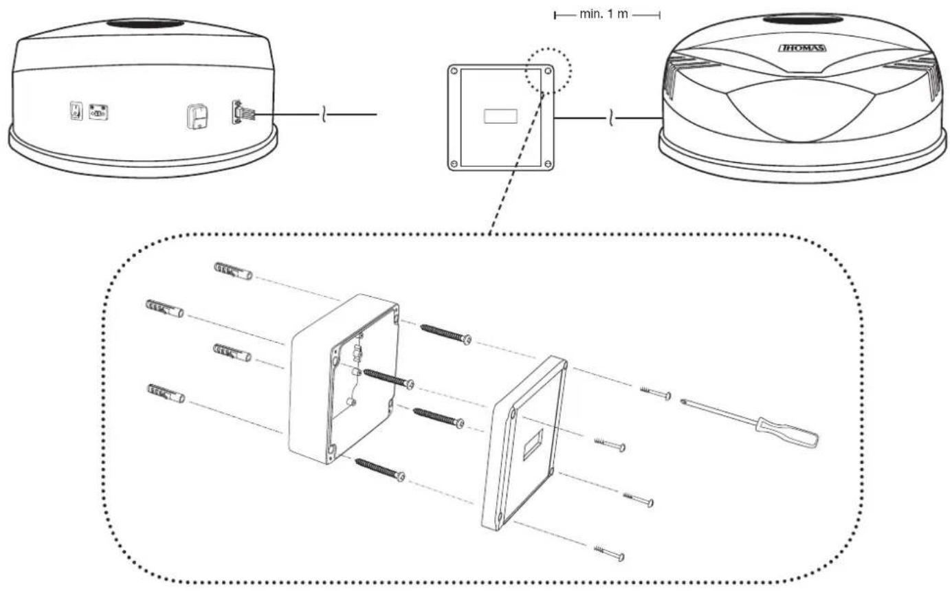
3.1.2 Assembly information for central vacuum unit with power control
Install the receiver unit with at least 1 m distance to the hood of the system on the wall next. To do this, fix the base plate of the receiver unit in the required position with four screws and screw the lid on the housing (see fig.). Connect the receiver unit and hood using the external connection cable.
3.2 Electrical connection
- Insert the mains plug of the connecting cable into the Schuko plug socket provided by the customer (230 V, 16 A) - Turn main switch to I.
3.3 Transmitter settings
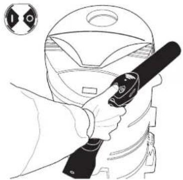
3.3.1 Teaching-in radio transmitter
To operate with the radio control, the system must be programmed to a radio transmitter.
- For this the integrated transmitter within the tube bend is exactly as shown,

to be kept close to the hood of the system.

to be kept close at the bottom left on the receiver unit.
- Press one of the two sender keys ( | or □ and LERN appears on the LCD display.
- Take away the sender/receiver unit from the system and repeat from a distance of approx. 1 metre and press one of the two sender keys again (within 60 seconds). Shown on the LCD is LN01 for 1 second.
Only after the OK display goes of after 3 seconds the sender has been teached-in and the system can be started via the | key.
natural_image
Line drawing of a person using a handheld device to clean a helmet (no text or symbols)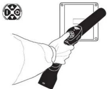
natural_image
Line drawing of a hand holding a handheld device with a circular symbol on the left (no text or symbols present)3.3.1.1 Teaching-in radio transmitter - faulty operation
LN01 will appear for 1 second on the LCD in case of faulty operation the time window of 60 seconds be exceeded and the learn function has not been correctly implemented. After this FAIL will appear for 3 seconds. This procedure repeats itself up to 10 times. Afterwards FFB and OPEN will appear alternately on the LCD in the case of initial installation.
The basic display will appear on the LCD in the case of already learned in senders
– The learn procedure is to be repeated.
3.3.2 Clearing the sender
If just one sender is cleared all teached-in radio transmitter or repeater will be deleted.
- To delete the transmitter hold the transmitter to the given position at the system, see figure above.
- Press sender O key and hold down for 5 seconds. Do not take away the transmitter from the system! LERN will appear for 2 seconds on the LCD, followed by CLR for 3 seconds. OK will appear for 2 seconds as return signal from the system.
FFB and OPEN will now be displayed alternately on the LCD.
Now new senders can be teached-in in again.
3.3.2.1 Clearing the sender - faulty operation
In the case of faulty operation, for example, when the sender key is held down for longer than 2 seconds, but for less than 5 seconds, CLR will appear on the LCD for 1 second followed by FAIL for 3 seconds. This process repeats itself up to 10 times, after which the basic display will appear on the LCD.
By pressing one of the two keys on the transmitter the faulty delete operation will be interrupted and a new attempt can be started.
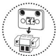
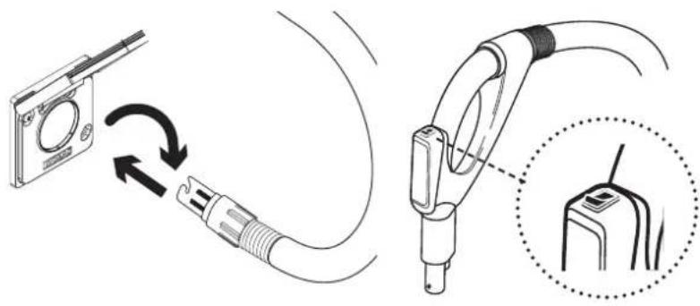
3.4 Control cable connection
- Pull out the contact plug of the control cable plug box. Then connect the on-site control line wires with the connector and insert and fix the control line socket.
natural_image
Diagram showing a device with three ports and an internal structure, enclosed in a dotted circle (no text or symbols)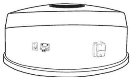
natural_image
Line drawing of a cylindrical device with a top handle and three small icons on the side (no text or symbols)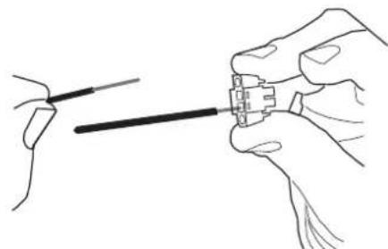
natural_image
Illustration of hands connecting a cable to a connector (no text or symbols present)4. Operation of central vacuum cleaner system
ATTENTION!
Never allow liquids to get into the suction and exhaust air system. Always use the THOMAS pre-separator INOX V 20 to vacuum up liquids, fine dust and course dirt.
Note:
- Do not switch on the system when all suction boxes are closed.
- To avoid damage to the system it will be automatically switched off after 15 minutes of operation. The system can be started again by pressing on the ON switch again depending on the actual mode of control (radio, control cable or appliance switch)
Radio: - press
| switch on sender
Control cable:
a) Comfort deluxe vacuum hose:
b) Comfort vacuum hose:
- Turn switch on the tube bend off and on again, - Take out the suction hose connection of the suction box and insert again. - Switch system off and on again via the appliance switch.
Appliance switch:
4.1 Operation by radio remote control
- Connect the telescopic tube to the Premium vacuum hose and the required accessory.
- Insert the suction hose with the bayonet connection into the required suction box and fasten securely.
- Press the | / Okey of the radio remote controll to start and end the vacuuming operation.
- Central vacuum system with power control:
▲ = 70 % of maximum capacity ▼ = 40 % of maximum capacity
If the central vacuum cleaner is not connected at the lowest point in the entire system (see planning brochure), a stopping time of approx. 10 seconds is to be maintained after the vacuuming operation to ensure that the vacuumed material may be picked up completely by the system. Only after this the vacuum cleaner can be switched off again: Now disconnect the suction hose from the suction box.
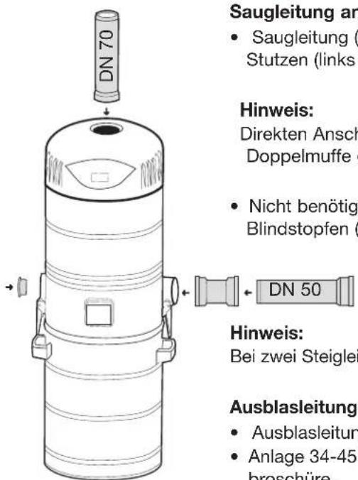
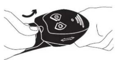
4.1.1 To change battery
The sender on the tube bend is equipped as standard with a powerful battery (Alkali/manganese cell). Should it be necessary to change the battery after an appropriate running time the sender cover is to be lifted off the tube bend by means of a flat object.
- Replace battery. Make sure that the polarity is correct.
- Hang in the cover behind the tube bend and push on from the top.
natural_image
Illustration of a hand holding a black remote control device with sensor icons and directional arrows (no text or symbols)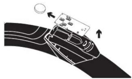
natural_image
Diagram of a car interior with a device on the roof and directional arrows indicating movement (no text or symbols)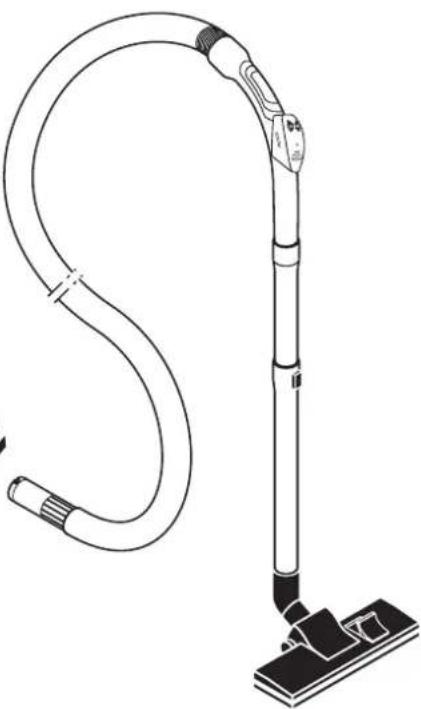
natural_image
Line drawing of a vacuum cleaner with attached cable and base mount (no text or symbols)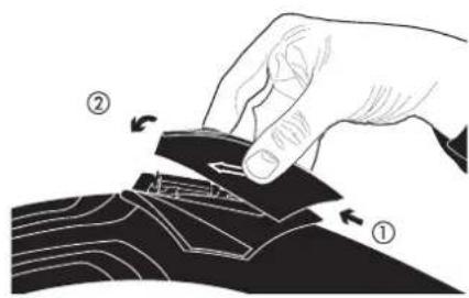
Batteriedatas:
Please observe the instructions for disposal
4.2 Operation through control cable
4.2.1 Comfort deluxe vacuum hose
- Connect the telescopic tube with the suction hose and the required accessory.
- Insert the suction hose by means of the bayonet connection in the appropriate suction box. The contact surfaces must face upwards.
- To start or end the vacuuming operation turn the switch on the tube bend on or off.
natural_image
Diagram showing cable connection between a device and a plug, with magnified detail of the plug's internal structure (no text or symbols)4.2.2 Comfort vacuum hose
- Connect the telescopic tube with the suction hose and the required accessory.
- Insert the suction hose by means of the bayonet connection on the appropriate suction box.
- Remove the suction hose from the suction box to end the operation.
Note:
After finishing the vacuuming process it is essential to remove the suction hose from the suction box because otherwise the central vacuuming unit will continue to run and only be turned off automatically after 15 minutes!
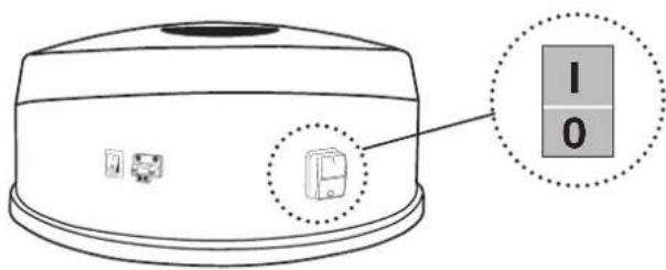
4.3 Operation through appliance switch
In the case of vacuuming through the appliance suction box the system can be switched directly through the appliance on and off switch.
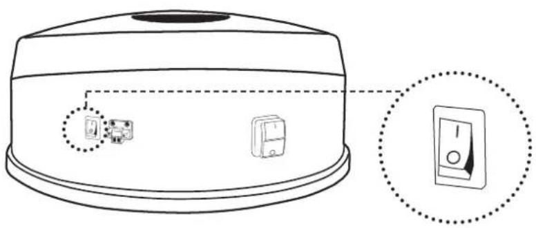
natural_image
Line drawing of a microwave oven with two labeled buttons and a close-up inset showing the right button (no text or symbols present)Note:
If the system is optionally running by radio or control cable the processor will only be completely turned off if all switch contacts are also turned off.
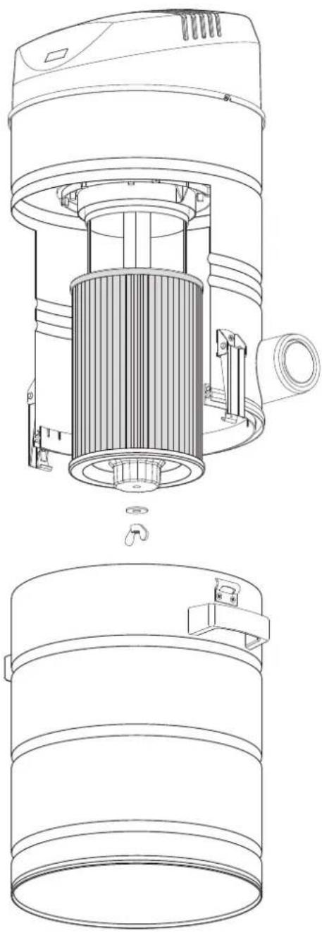
5. To change cartridge filter
Replace or clean the dust bag and cartridge filter at the latest every 6 months or after approx. 25 working hours. This depends on the amount of dust collected in the dust bag.
The extent to which fluff and dust accumulates at the cartridge filter depends on dust type and suctioning and is quite normal.
It has hardly any effect on the suction power.
Do not fail to keep to the stipulated cleaning intervals!
Cleaning/changing the cartridge filters
- Turn off the vacuum cleaner and pull out the mains plug.
- Open the snappers at the vacuum cleaner, take out the dust container and place under the vacuum cleaner.
- Slacken the wing nut and twist it together with the flat washer off from the threaded rod retainer.
- Pull the cartridge filter downwards.
Pointer:
For an easier, cleaner removal of the cartridge filter we would recommend – before removal – pulling a PE dust bag from below over the cartridge filter. This together with the PE dust bag is then to be fully removed downwards.
- Slip the cleaned/new cartridge filter with the flat washer centrally onto the threaded rod retainer up to the top stopper.
- Secure the cartridge filter with the wing nut and the flat washer. Hand-tighten the wing nut.
- Re-fit the emptied dust container to the vacuum cleaner and secure in place by closing the snappers.

Important!
Do never use the vacuum system without a filter or if the filter is damaged!
Note:
The THOMAS filter bag set can be used to dispose of the suctioned material (special accessory).
The vacuum socket of the Centra Clean 18-451 system may not be used in connection with the filter bag!
natural_image
Technical line drawing of a mechanical device showing internal components and assembly (no text or symbols)6. Help in the case of irregularities
IMPORTANT!
Always disconnect the mains plug before opening the appliance!
Small irregularities are often caused by mistakes made by the user and can be very often remedied by the user himself. Should it not be possible to eliminate any irregularity you should get in touch with your specialist dealer or directly with the THOMAS customer service department. In this case have the information to be found on the type shield ready to hand.
| Irregularities Possible causes Remedy | ____ | |
| Sudden interruption in operation | Appliance has automatically switched off after 15 minutes vacuuming (safety function!);appliance also switches off automatically, possibly when blocked or through overloading | Switch on again.Allow motor to cool down, clear any possible blockage, then switch on again. |
| Vacuum cleaner does not start – Radio– Control cable | Vacuum cleaner not switched on.Remote radio controller batteries are empty;sender in non-reception area;Inadequate sender performance.Radio receiver unit not connected.No signal given to receiver.Suction hose has not been locked properly in the suction box | Switch on vacuum cleaner.Change batteries;change your position in the room;repeater insert necessary (special accessory).Connect up radio receiver unit.Reprogram the sender. Place the receiver at least two meters in front of the vacuum cleaner.Check connection. |
| Sudden loss of suction power | Suction hose buckled;Secondary air source, for example has a second open vacuum socketCover on one of the air plug boxes is not closed airtight;bulky pieces of material in front of the coarse dirt guard;Blocked exhaust air openings on the outside wall on the site (for example by foliage). | Straighten suction hose, eliminate buckling;close secondary air source;clean or replace seal;remove blockage;remove blockage |
7. Cleaning and servicing
- Regularly remove the dust and dirt collection in the coarse dirt guard.
- Change the cartridge filter at the recommended intervals.
- Change the remote controller batteries after elapse of the stipulated number of working hours.
8. Disposal
– Used radio receiver units, radio remote controllers and batteries have to be placed separately in a public collection container or handed to your dealer.
As the final consumer you are statutorily obliged (Battery ordinance) to return all used batteries and rechargeables; they must not be disposed of in the household refuse.
Hg
Batteries and rechargeables containing pollutants, for instance, are marked with the symbol on the left. It refers to the prohibition of the disposal in the household refuse.
The designation under the symbol stands for the heavy metal which is paramount, such as Hg = mercury; Cd = cadmium; Pb = lead.
You can hand in used batteries, rechargeables and button cells free of charge either at your municipality's collection points or anywhere where batteries / rechargeables / button cells are sold. In this way, you both comply with the statutory obligations and make your own contribution to environmental protection.
- Cut off all mains cable to prevent misuse.
- Other parts of the appliance and packaging material are to be disposed of according to the valid regulations by the municipal waste disposal company.

The company Robert Thomas Metall und Elektrowerke GmbH & Co. KG hereby declares that this unit conforms to the basic requirements and to other relevant regulations of the Directive 1999/5/EC. The complete CE Declaration of Conformity can be requested using our address information (see back).
The symbol on the product or on its packaging indicates that this product may not be treated as normal household waste but must be taken to a collection point for the recycling of electrical and electronic equipment.
By ensuring that this product is disposed of in the correct manner you are protecting the environment, your own health and the health of other people. The environment and health are put at risk by incorrect disposal.
For more information about recycling this product, contact your local council, your household waste disposal service or the shop where you purchased the product.
Chère cliente, cher client,
natural_image
Line drawing of a hand holding a tool inside a helmet (no text or symbols)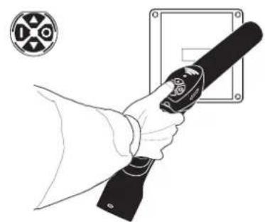
natural_image
Line drawing of a hand holding a flashlight with a circular emblem in the background (no text or symbols)natural_image
Illustration of hands holding a medical device with a circular sensor icon and directional arrows (no text or symbols)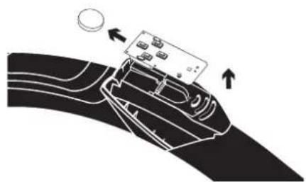
natural_image
Diagram of a hand holding a device with directional arrows indicating movement (no text or symbols)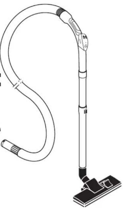
natural_image
Line drawing of a vacuum cleaner with attached circuit board (no text or symbols)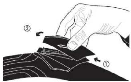
Nota bene:
natural_image
Technical line drawing of a cylindrical device with internal components and mounting brackets (no text or symbols)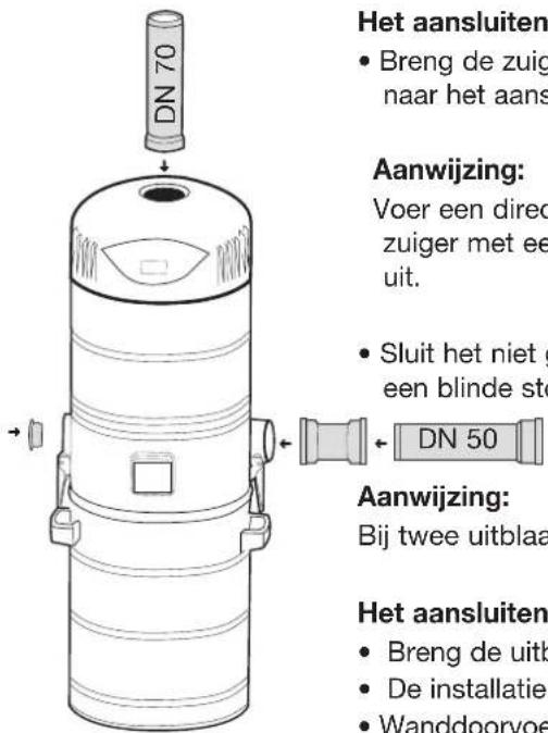
3.3 Zenderinstellingen
3.3.1 Zender programmeren
natural_image
Line drawing of a person using a handheld device to clean a helmet (no text or symbols)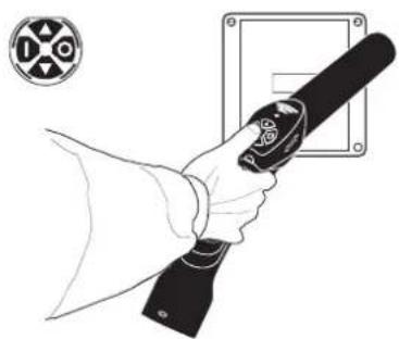
natural_image
Line drawing of a hand holding a flashlight with a circular emblem in the background (no text or symbols)3.3.1.1 Zender aanleren – foutbediening
natural_image
Illustration of a hand holding a device with a circular sensor or sensor icon, no text or symbols present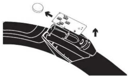
natural_image
Diagram of a device being processed into a curved surface, showing directional arrows (no text or symbols)
natural_image
Line drawing of a vacuum cleaner with attached circuit board (no text or symbols)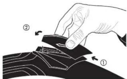
Batterijgegevens:
4.2.2 Comfort-zuigslang
Aanwijzing:
natural_image
Technical line drawing of a mechanical device showing internal components and assembly (no text or symbols)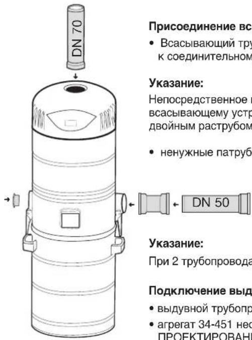
natural_image
Line drawing of a person using a handheld device to clean a helmet (no text or symbols)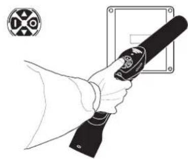
natural_image
Line drawing of a hand holding a handheld device with a circular symbol in the background (no text or symbols present)natural_image
Illustration of hands holding a device with a circular sensor or sensor icon (no text or symbols)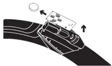
natural_image
Diagram of a car interior with a device and directional arrows indicating movement (no text or symbols)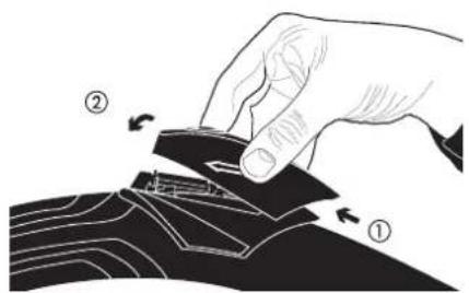
Данные батареи:
natural_image
Technical line drawing of a cylindrical device with internal components and mounting holes (no text or symbols)


- Saugschlauch-Comfort
- Hinweis:
- CAUTION!
- SAFETY REGULATIONS
- IMPORTANT!
- The use of the building drainage system for the exhaust air lines is not permitted!
- Installation of the central vacuuming system
- Installation of central vacuum cleaner
- Mounting the unit
- To connect suction line
- Note:
- Connect exhaust line
- Filter system
- Assembling cartridge filter
- Important
- Electrical connections
- Wireless connection ( U = central vacuum unit without power control / U central vacuum unit with power control)
- General instructions
- Assembly information for central vacuum unit with power control
- Electrical connection
- Transmitter settings
- Teaching-in radio transmitter
- Teaching-in radio transmitter - faulty operation
- Clearing the sender
- Clearing the sender - faulty operation
- Control cable connection
- Operation of central vacuum cleaner system
- ATTENTION!
- Control cable:
- Operation by radio remote control
- To change battery
- Operation through control cable
- Comfort deluxe vacuum hose
- Comfort vacuum hose
- Operation through appliance switch
- To change cartridge filter
- Cleaning/changing the cartridge filters
- Pointer:
- Help in the case of irregularities
- Always disconnect the mains plug before opening the appliance!
- Cleaning and servicing
- Disposal
- Nota bene:
- Zenderinstellingen
- Zender programmeren
- Zender aanleren – foutbediening
- Comfort-zuigslang
- Aanwijzing:
Brand : THOMAS
Model : CentraClean 15301
Category : Vacuum Cleaner