
Variant View S1620SV - Sauna HARVIA - Free user manual and instructions
Find the device manual for free Variant View S1620SV HARVIA in PDF.
| Product Type | Prefabricated wooden sauna cabin |
| Brand | Harvia |
| Model | Variant View S1620SV |
| External dimensions (L x W x H) | 1992 x 1522 x 2020 mm |
| Estimated weight | Approximately 280 kg |
| Main material | Spruce wood |
| Capacity | Up to 4 people |
| Electrical supply | Connection by qualified electrician for the stove (not included) |
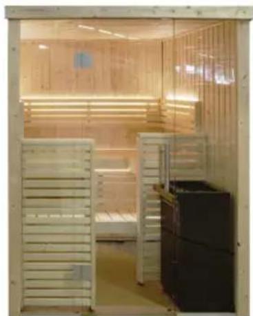
| Main features | Sauna cabin with benches, glass door, optional LED lighting, ventilation |
| Integrated lighting | Yes, model SAS21060T included, RGBW LED options available |
| Ventilation | Ventilation register included, placement diagonally from the stove |
| Glass door | Tempered glass 8 mm thick, opens outward |
| Benches | Upper and lower wooden bench, with backrest and footrest |
| Assembly | Requires 2 people, tools: hammer, screwdriver, level, drill bits |
| Maintenance | Clean with a damp cloth and hot water only |
| Resin cleaning | Use a cloth soaked in acetone or scrape once hardened |
| Safety | At least 5 cm distance from wall, horizontal and sturdy floor, tempered glass fragile |
| Included parts | Floor frame, wall elements, roof, benches, glass door, mounting hardware |
| Optional accessories | RGBW LED tubes, Xenio control, power supply unit |
| Warranty | Refer to retailer (not specified in the manual) |
| Manual | 128 pages, available in multiple languages on harvia.com |
Frequently Asked Questions - Variant View S1620SV HARVIA
User questions about Variant View S1620SV HARVIA
0 question about this device. Answer the ones you know or ask your own.
Ask a new question about this device
Download the instructions for your Sauna in PDF format for free! Find your manual Variant View S1620SV - HARVIA and take your electronic device back in hand. On this page are published all the documents necessary for the use of your device. Variant View S1620SV by HARVIA.
USER MANUAL Variant View S1620SV HARVIA
natural_image
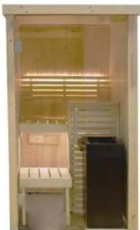
Interior view of a simple indoor space with a bench, wall-mounted equipment, and a slatted structure (no visible text or symbols)Small
1635 x 1608 x 2020 mm
natural_image
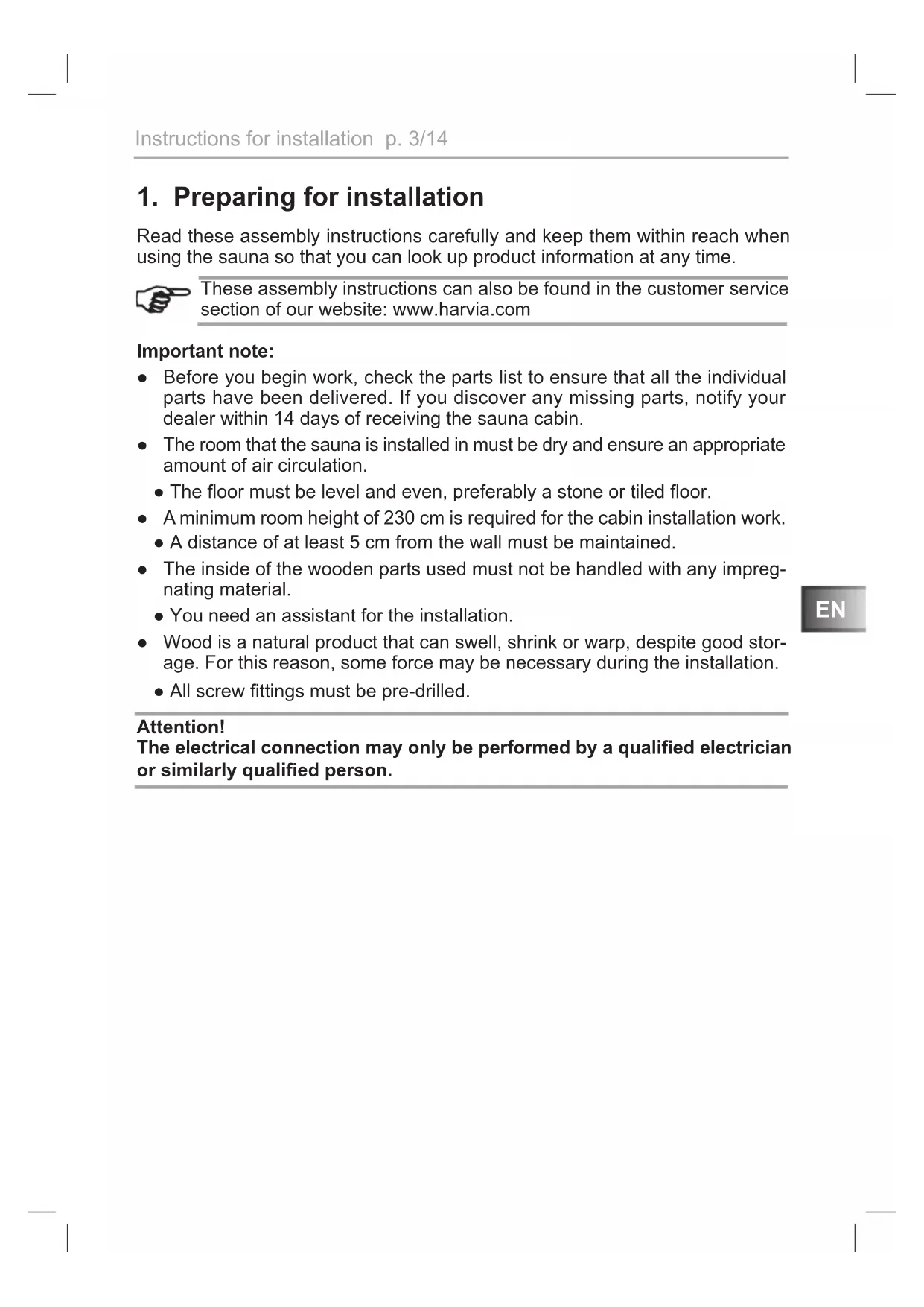
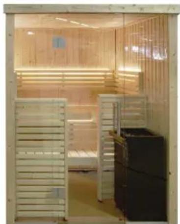
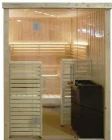
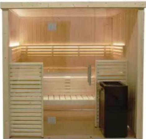
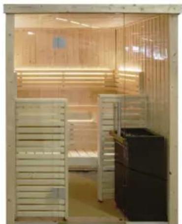
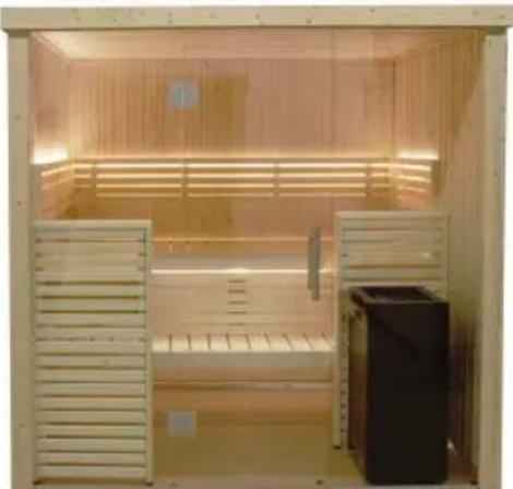
Interior view of a modular dormitory or exercise room with wooden paneling, a single bunk bed, and a black refrigerator (no visible text or symbols)Medium Large
S1620SV S2020SV
2060×1608×2020mm 2060×2033×2020mm

natural_image
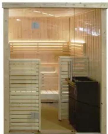
Interior view of a wooden steamer cabin with slatted windows and a refrigerator (no visible text or symbols)
natural_image
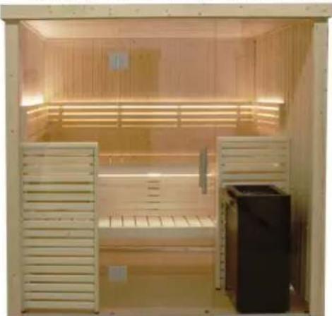
Interior view of a wooden steamer with slatted panels and a refrigerator (no visible text or symbols)Sisällys
natural_image
Two abstract diagrams showing a rectangular object intersected by two lines, with no visible text or symbols.natural_image
Interior view of a simple indoor space with a small bench, a ladder, and a large wall-mounted shelf (no visible text or symbols)Small
1635 x 1608 x 2020 mm
natural_image
Interior view of a wooden anxiety chamber with slatted panels and a black refrigerator (no visible text or symbols)Medium Large
S1620SV S2020SV
2060×1608×2020mm 2060×2033×2020mm
natural_image
Interior view of a wooden indoor space with slatted bamboo, no visible text or symbols
natural_image
Interior view of a wooden steamer with slatted doors and a refrigerator (no visible text or symbols)natural_image
Two abstract geometric diagrams showing intersecting lines and shaded regions, no text or symbols present.natural_image
Interior view of a room with a small machine, a ladder, and a dark cabinet (no visible text or symbols)Small
1635 x 1608 x 2020 mm
natural_image
Interior view of a modern indoor facility with wooden paneling and a refrigerator (no visible text or symbols)Medium Large
S1620SV S2020SV
2060 × 1608 × 2020 mm 2060 × 2033 × 2020 mm
natural_image
Interior view of a wooden anxiety chamber with slatted vent and side bays (no text or symbols visible)
natural_image
Interior view of a wooden steamer cabin with slatted doors and a refrigerator (no visible text or symbols)Table of Contents
1. Preparing for installation 3
1.1. Tools required 4
1.2. Maintenance and cleaning 5
1.3. Disposal 5
1.4. Parts list for Mini S1212SV and Small S1616SV 6
1.5. Parts list for Medium S1620SV and Large S2020SV 8
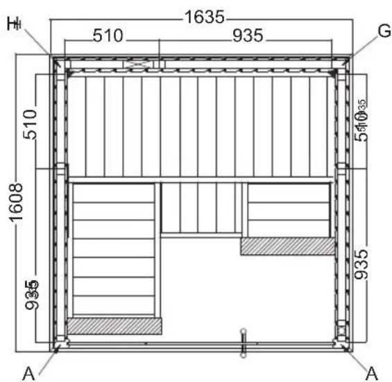
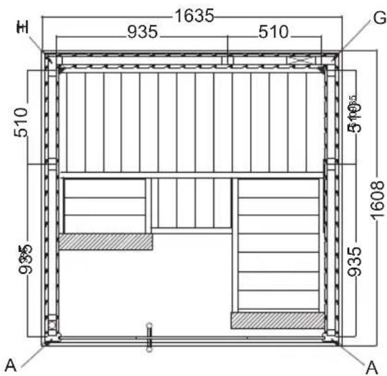
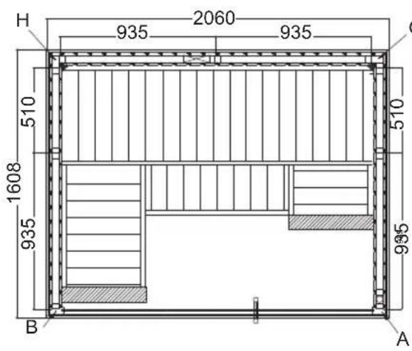
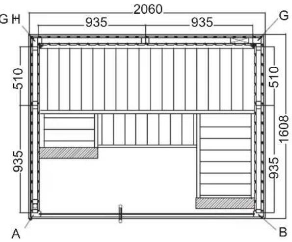
2. Floor plan 10
2.1. Variant View Mini S1212SV 10
2.2. Variant View Small S1616SV 10
2.3. Variant View Medium S1620SV 11
2.4. Variant View Large S2020SV 11
3. Assembling the cabin 12
3.1. Assembling the base frame 12
3.2. Assembling the cabin walls 12
3.3. Assembling the roof elements 12
3.4. Assembling the benches 12
3.5. Assembling the glass elements 13
3.6. Installing roof trim 13
3.7. Mounting the cover slats 13
3.8. Drill hole for electrical cable 13
3.9. Mounting the light 13
3.10. Installation KIT for heater installation at the bench foot....13
Illustrations for the parts list
(following the last language of the instructions)____15
Assembly illustrations
(following the last language of the instructions) 16
1. Preparing for installation
Read these assembly instructions carefully and keep them within reach when using the sauna so that you can look up product information at any time.

These assembly instructions can also be found in the customer service section of our website: www.harvia.com
Important note:
- Before you begin work, check the parts list to ensure that all the individual parts have been delivered. If you discover any missing parts, notify your dealer within 14 days of receiving the sauna cabin.
- The room that the sauna is installed in must be dry and ensure an appropriate amount of air circulation.
- The floor must be level and even, preferably a stone or tiled floor.
- A minimum room height of 230 cm is required for the cabin installation work.
- A distance of at least 5 cm from the wall must be maintained.
- The inside of the wooden parts used must not be handled with any impregnating material.
- You need an assistant for the installation.
- Wood is a natural product that can swell, shrink or warp, despite good storage. For this reason, some force may be necessary during the installation.
- All screw fittings must be pre-drilled.
Attention!
The electrical connection may only be performed by a qualified electrician or similarly qualified person.
1.1. Tools required
- Hammer with a wooden head or a mallet
- Cordless screwdriver with bits for cross-head screws and Torx
- Roller tape measure
-
Drill bits with a diameter of 3 mm, 10 mm, 20 - 30 mm (for sauna heater power cable)
-
Spirit level
• 1.5 mm hexagonal socket wrench - Utility knife
- Ladder
This symbol indicates tips and useful information
Pre-drill

Nailing
Check the right angle:
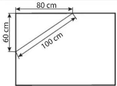
Handle glass with care: Special care must be taken with the edges of the glass – hardened glass can shatter into small pieces in the event of impact. Insert protective cushioning (e.g: cardboard box) under the edge of the glass.
natural_image
Two diagrams showing a transparent rectangular object intersected by two diagonal lines, with no text or symbols present.1.2. Maintenance and cleaning
- The sauna should be cleaned with a damp cloth. Only use warm water – no cleaning products.
- We recommend heating the cabin once a month if the sauna is not used for a long time.
Pitch pockets are not grounds for return, since they can always appear in spruce wood and the depth at which they lie cannot be detected during the sorting-out process.
If these are just under the surface, heat can cause them to soften and "bleed".
The leaking pitch can be removed with a rag soaked in acetone. If only droplets of pitch occur, allow these to harden and then carefully scrape them off with a knife.
1.3. Disposal
- Dispose of packaging materials in accordance with the applicable waste disposal regulations.
- Used devices contain reusable materials as well as hazardous substances. Therefore, do not dispose of your used device with household waste, but do so in accordance with the locally applicable regulations.
1.4. Parts list for Mini S1212SV and Small S1616SV
Illustrations for parts on page 11 (following the last language of the instructions)
| No. | Name Pcs Dimensions(mm) | Pcs Dimensions(mm) | |||
| S1212SV | S1616SV | ||||
| Base frame | |||||
| 1 | Base frame 1 1097x68x43 1 1522x68x43 | ||||
| 2 | Base frame 1 1142x68x43 1 1567x68x43 | ||||
| 3 | Base frame ventilation aperture 1 1097x68x43 1 1522x68x43 | ||||
| Wall elements | |||||
| 4 | Wall elements 510 4 | 1900x510x75 2 | 1900x510x75 | ||
| 4 | Wall elements 935 | 2 | 1900x935x75 | ||
| 5 | Electrical element 510 | 1 | 1900x510x75 | ||
| 5 | Electrical element 935 | 1 | 1900x935x75 | ||
| 6 | Ventilation element 510 | 1 | 1900x510x75 | 1 | 1900x510x75 |
| Corner posts | |||||
| 7 | Corner post A | 1 | 1949x85x45 2 | 1949x85x45 | |
| 8 | Corner post B | 1 | 1949x73x45 | ||
| 9 | Corner post G | 1 | 1836x77x76 1 | 1836x77x76 | |
| 10 | Corner post H | 1 | 1836x77x44 1 | 1836x77x44 | |
| Roof elements | |||||
| 11 | Roof element | 1 | 1144x1172x64 | 1 | 1597x883x64 |
| 12 | Roof element | 1 | 1597x686x64 | ||
| 13 | Roof frame | 1 | 1142x45x32 2 | 1395x45x32 | |
| 13 | Roof frame | 2 | 970x45x32 | 1 | 1567x45x32 |
| 13 | Roof frame | ||||
| 14 | Roof rim | 2 | 1210x95x15 2 | 1605x95x15 | |
| 14 | Roof rim | 2 | 1183x95x15 2 | 1633x95x15 | |
| Corner covers | |||||
| 15 | Inner roof corner trims | 2 | 1005x18x15 2 | 1430x18x15 | |
| 15 | Inner roof corner trims | 1 | 1022x18x15 1 | 1447x18x15 | |
| 16 | Inner corner trim | 2 | 1025x20x20 2 | 1025x20x20 | |
| 17 | Outer corner covers | 2 | 1900x77x15 2 | 1900x77x15 | |
| 18 | Outer corner covers | 1 | 1900x64x15 1 | 1900x64x15 | |
| 19 | Outer corner covers | 1 | 1900x64x15 1 | 1900x64x15 | |
| No. | Name Pcs Dimensions(mm) | Pcs Dimensions(mm) | ||||
| S1212SV | S1616SV | |||||
| Glass front | ||||||
| 20 | Aluminium U-profile 1 402x22x12 2 409x22x12 | |||||
| 21 | Glass 1 1939x411x8 2 1939x417x8 | |||||
| 21 | Glass door 1 1897x600x8 1 1897x600x8 | |||||
| 22 | Spacer strip above glass door 1 | 610x20x8 1 | 610x20x8 | |||
| 23 | Door handle set | 1 300x158x30 1 300x158x30 | ||||
| 24 | Door hinges | 2 | 2 | |||
| Interior fittings | ||||||
| 25 | Upper sauna bench 1 | 1015x500x90 1 | 1440x600x90 | |||
| 25 | Upper sauna bench | 1 680x500x90 | ||||
| 25 | Upper sauna bench | 1 500x285x90 | ||||
| 25 | Lower sauna bench | 1 1440x400x90 | ||||
| 26 | Bench foot | 1 | 1143x510x90 | 2 | 1143x510x90 | |
| 27 | Foot step | 1 475x400x90 | ||||
| 28 | Feet | 4 431x90x28 | ||||
| 29 | Bench screen | 1 525x402x42 1 | 1370x402x42 | |||
| 30 | Backrests | 1 978x270x36 1 | 1400x270x36 | |||
| 30 | Backrests | 1 | 1234x270x36 | |||
| 30 | Backrests | 1 840x270x36 | ||||
| 31 | Bench support slat | 2 495x99x29 2 900x90x29 | ||||
| 32 | Bench support slat | |||||
| 33 | Bench support slat | 1 468x90x29 2 900x90x29 | ||||
| 33 | Bench support slat | 2 700x90x29 | ||||
| Accessories | ||||||
| 35 | Ventilation slit | 1 260x87x20 1 260x87x20 | ||||
| 36 | Light (SAS21060T) | 1 200x100x65 1 200x100x65 | ||||
| 37 | Installation material | 1 | 1 | |||
| 38 | Kit for heater mounting on bench foot | 1 | 1 | |||
| 39 | Assembly instructions | 1 | 1 | |||
| Accessories (optional) | ||||||
| RGBW LED Tube | 2 | LED-tube 900 | 1 | LED-tube 700 | ||
| RGBW LED Tube | 1 | LED-tube 1200 | ||||
| RGBW LED Tube | 1 | LED-tube 1300 | ||||
| Xenio RGBW colour light control | 1 | 1 | ||||
| DMX-Driver (DMX-C) | 1 | 1 | ||||
| Power supply unit (LED-PWS-24-XX) | 1 | 40 W | 1 | 90 W | ||
1.5. Parts list for Medium S1620SV and Large S2020SV
Illustrations for parts on page 11 (following the last language of the instructions)
| No. | Name Pcs Dimensions(mm) | Pcs Dimensions(mm) | ||
| S1620SV | S2020SV | |||
| Base frame | ||||
| 1 | Base frame 1 1522x68x43 1 1947x68x43 | |||
| 2 | Base frame 1 1992x68x43 1 1992x68x43 | |||
| 3 | Base frame ventilation aperture 1 1522x68x43 1 1947x68x43 | |||
| Wall elements | ||||
| 4 | Wall elements 935 2 1900x935x75 4 1900x935x75 | |||
| 4 | Wall elements 510 2 1900x510x75 | |||
| 5 | Electrical element 935 | 1 1900x935x75 1 1900x935x75 | ||
| 6 | Ventilation element 935 | 1 1900x935x75 1 1900x935x75 | ||
| Corner posts | ||||
| 7 | Corner post A | 2 1949x85x45 2 1949x85x45 | ||
| 9 | Corner post G | 1 1836x77x76 1 1836x77x76 | ||
| 10 | Corner post H | 1 1836x77x44 1 1836x77x44 | ||
| Roof elements | ||||
| 11 | Roof element | 1 2022x883x64 | 1 2022x1112x64 | |
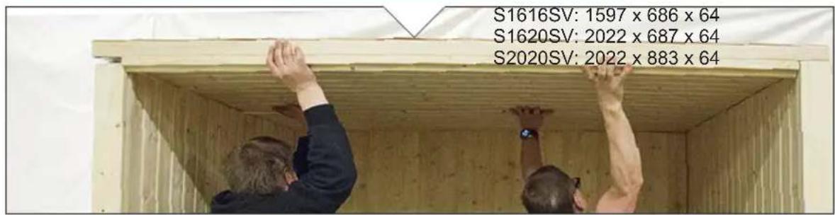
| 12 | Roof element | 1 2022x687x64 1 2022x883x64 | ||
| 13 | Roof frame | 1 1992x45x32 1 1992x45x32 | ||
| 13 | Roof frame | 2 1395x45x32 2 1819x45x32 | ||
| 14 | Roof rim | 2 2058x95x15 2 2058x95x15 | ||
| 14 | Roof rim | 2 1605x95x15 2 2033x95x15 | ||
| Corner covers | ||||
| 15 | Inner roof corner trims | 1 1868x18x15 | 1 1868x18x15 | |
| 15 | Inner roof corner trims | 2 1426x18x15 | 2 1850x18x15 | |
| 16 | Inner corner trim | 2 1025x20x20 2 1025x20x20 | ||
| 17 | Outer corner covers | 2 1900x77x15 2 1900x77x15 | ||
| 18 | Outer corner covers | 1 1900x64x15 1 1900x64x15 | ||
| 19 | Outer corner covers | 1 1900x64x15 1 1900x64x15 | ||
| Glass front | ||||
| 20 | Aluminium U-profile 2 621x22x12 2 621x22x12 | |||
| 21 | Glass 2 1939x629x8 2 1939x629x8 | |||
| 21 | Glass door 1 1897x600x8 1 1897x600x8 | |||
| 22 | Spacer strip above glass door 1 610x20x8 1 610x20x8 | |||
| 23 | Door handle set 1 300x158x30 1 300x158x30 | |||
| 24 | Door hinges 2 2 | |||
| Interior fittings | ||||
| 25 | Upper sauna bench 1 1865x600x90 1 1865x600x90 | |||
| 25 | Upper sauna bench 1 680x500x90 1 1165x500x90 | |||
| 25 | Upper sauna bench 1 500x285x90 1 582x500x90 | |||
| 25 | Lower sauna bench 1 1865x400x90 1 1865x500x90 | |||
| 26 | Bench foot | 2 1143x510x90 | 2 1143x510x90 | |
| 29 | Bench screen | 1 1795x402x42 1 1795x402x42 | ||
| 30 | Backrests | 1 1828x270x36 1 1828x270x36 | ||
| 30 | Backrests | 1 1234x270x36 1 1720x270x36 | ||
| 30 | Backrests | 1 839x270x36 1 136x270x36 | ||
| 32 | Bench support slat | 2 850x99x29 2 1050x90x29 | ||
| 33 | Bench support slat | 1 950x90x29 2 1050x90x29 | ||
| 33 | Bench support slat | 1 700x90x29 | ||
| 34 | Bench support leg | 1 845x68x44 1 845x68x44 | ||
| 34 | Bench support leg | 1 395x68x44 1 395x68x44 | ||
| Accessories | ||||
| 35 | Ventilation slit | 1 260x87x20 1 260x87x20 | ||
| 36 | Light (SAS21060T) | 1 200x100x65 1 200x100x65 | ||
| 37 | Installation material | 1 1 | ||
| 38 | Kit for heater mounting on bench foot | 1 1 | ||
| 39 | Assembly instructions | 1 | 1 | |
| Accessories (optional) | ||||
| RGBW LED Tube | 1 LED-tube 700 | 1 LED-tube 1200 | ||
| RGBW LED Tube | 1 LED-tube 1200 | 1 LLED-tube 1600 | ||
| RGBW LED Tube | 2 LED-tube 1300 | 2 LED-tube 1800 | ||
| Xenio RGBW colour light control | 1 1 | |||
| DMX-Driver (DMX-C) | 1 1 | |||
| Power supply unit (LED-PWS-24-XX) | 1 160 W | 1 160 W | ||
2. Floor plan
2.1. Variant View Mini S1212SV
2.2. Variant View Small S1616SV
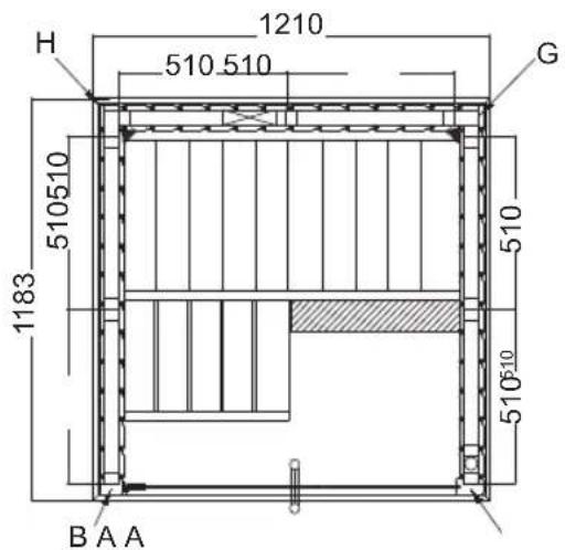
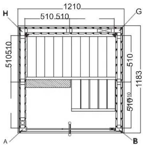
2.3. Variant View Medium S1620SV
2.4. Variant View Large S2020SV
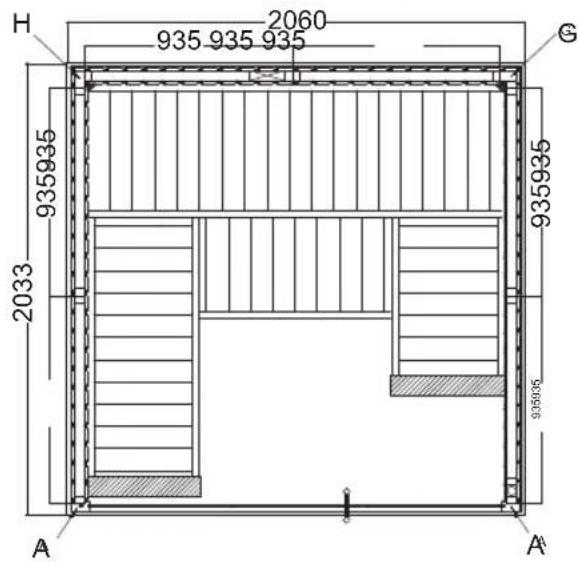
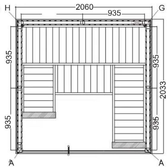
3. Assembling the cabin

ATTENTION!
Note the floor plans on pages 10 and 11 as well as the illustrations starting on page 16 (following the last language of the instructions).
3.1. Assembling the base frame
Start with the base frame and screw it to the corners. Move the base frame to the final position of the sauna.
3.2. Assembling the cabin walls
Note the outside/inside of the wall elements.
Make sure the ventilation element is correctly positioned. It must be placed diagonally opposite the heater.
Start assembling the wall elements with the ventilation element and screw it to the corner post (G, H). The other wall elements are connected by tongue and groove and are fixed by mounting the roof frame. Check the right angles (see tip on page 4).
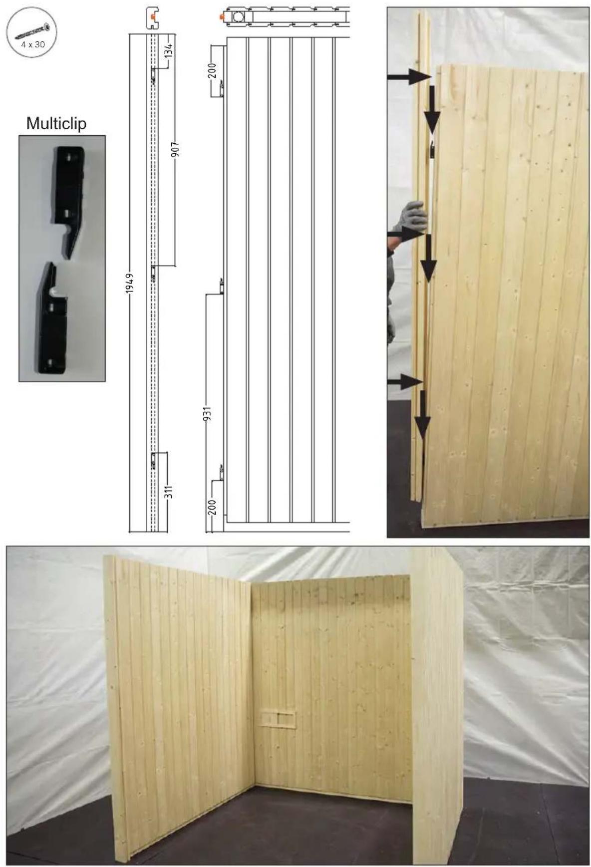
Mount the multiclips to the front sides of the wall elements and to the corner posts (A, B). Make sure that the multiclips are correctly aligned – the corner posts are connected to the wall elements from top to bottom.
Fit the ventilation slider.
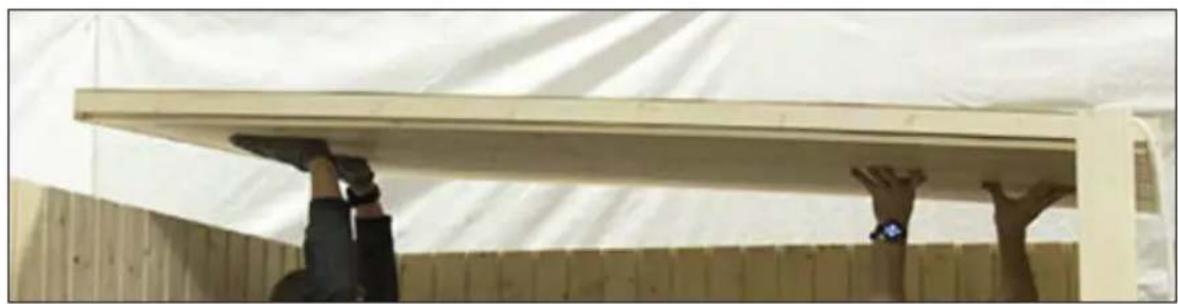
3.3. Assembling the roof elements
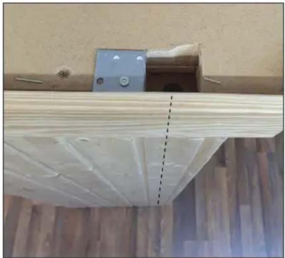
Insert the roof elements and screw them to the cabin walls. Note the cable outlet.
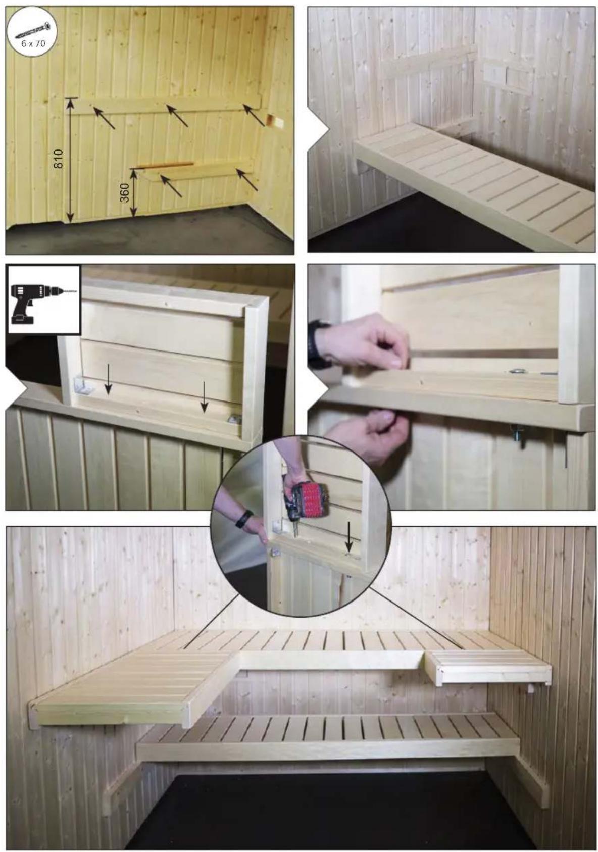
3.4. Assembling the benches
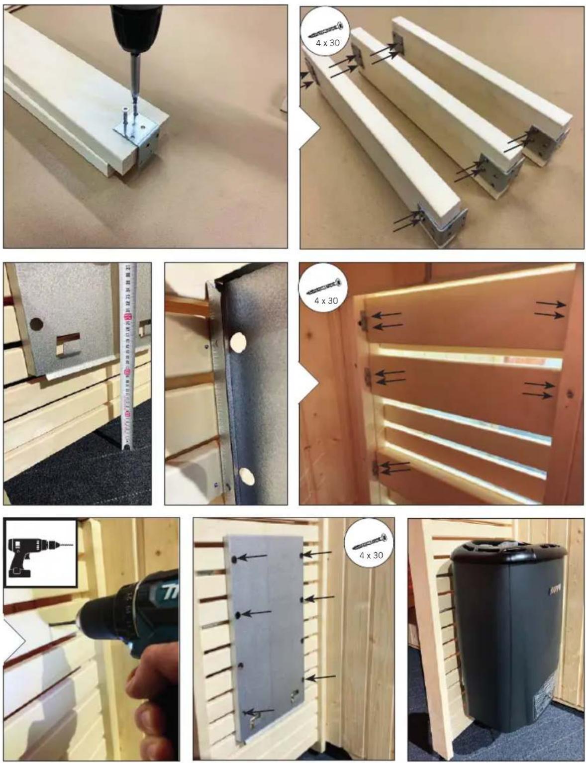
Mount the bench support slats on the side wall elements. Connect the angle bench to the sauna bench using M10 x 120 screws. Screw the adjustable feet into the bench foot. Fix the bench foot to the angled bench by tightening up the lock and screw the bench foot to the side wall.
Assemble the bench screen and the backrest.
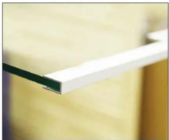
3.5. Assembling the glass elements
Fit the aluminium U-profiles on the glass elements and install the glass elements in the cabin.
Note when installing the glass element that the holes drilled for the door hinges determine which way the door opens.
Bond the aluminium U-profiles to the floor with silicone or assembly adhesive.
Mount the spacer strip above the glass door.
When installing the door fittings, make sure that the door opens to the outside.
Screw the two door fittings to the glass element first, making sure that the fittings are aligned straight. Align the fittings by adjusting / turning the two plastic inserts.
The door handles are screwed together from the inside. Attach plastic washers on the stainless steel handle
Fit the door magnet and sleeve plate.
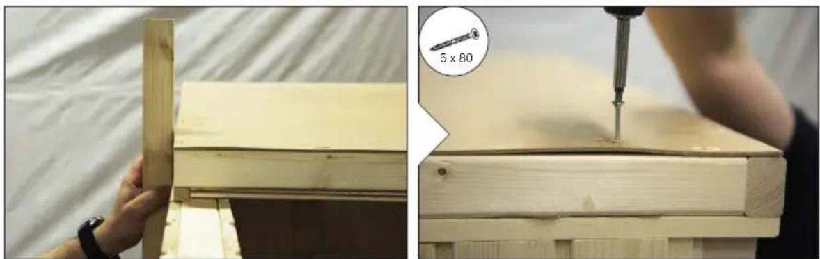
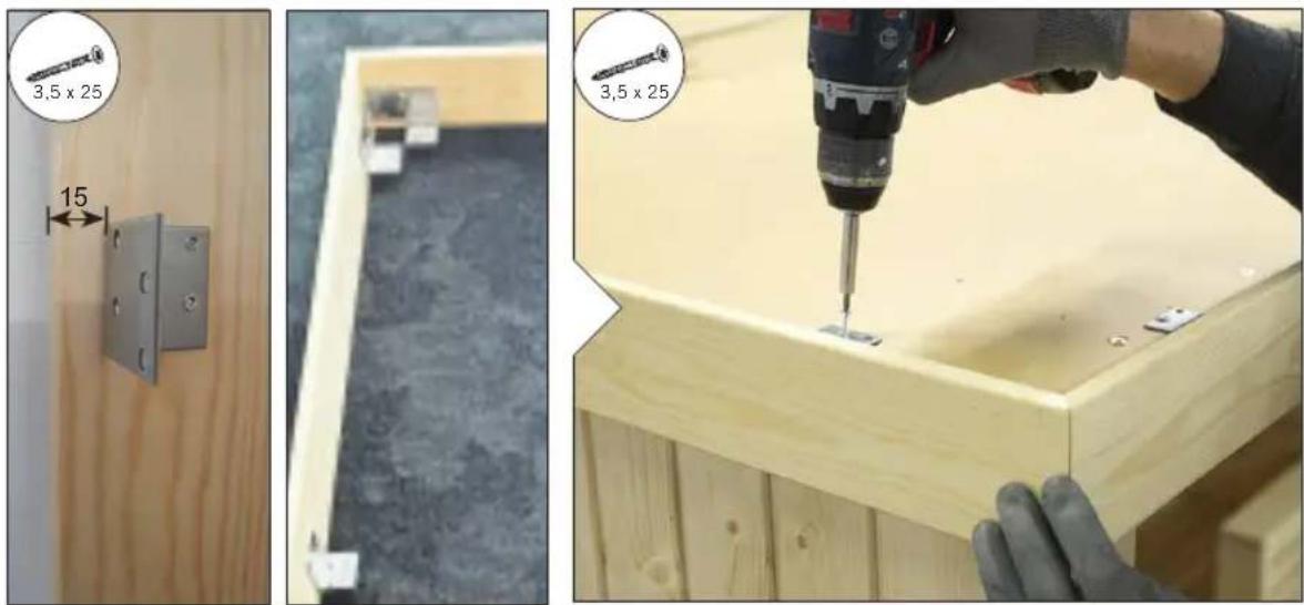
3.6. Installing roof trim
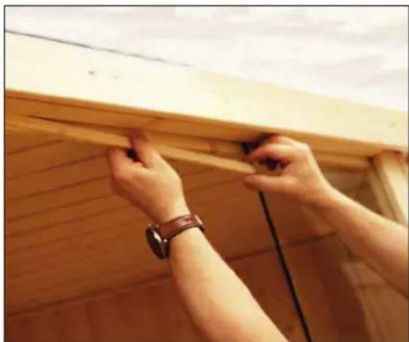
Mount the corner brackets to the roof trim strips. Then screw the roof trim strips to the roof element.
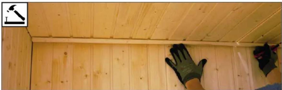
3.7. Mounting the cover slats
Fasten the inner roof corner trims, the inner corner trims and the outer corner covers using nails.
3.8. Drill hole for electrical cable
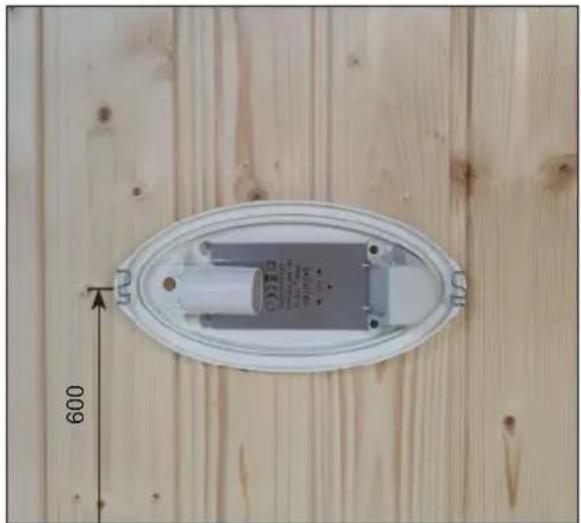
3.9. Mounting the light
3.10. Installation KIT for heater installation at the bench foot
Only required if the sauna heater is mounted on the bench foot in order to maintain the safety distances.
Instructions for installation p. 14/14
Elementsauna
VARIANT VIEW
MONTAGEANLEITUNG
Deutsch
Mini
S1212SV S1616SV
1210 x 1183 x 2020 mm
natural_image
Interior view of a room with a small machine, a ladder, and a cabinet (no visible text or symbols)Small
1635 x 1608 x 2020 mm

natural_image
Interior view of a modular room with wooden panels, a bed, and a refrigerator (no visible text or symbols)Medium Large
S1620SV S2020SV
2060×1608×2020mm 2060×2033×2020mm

natural_image
Interior view of a wooden anxiety chamber with slatted panels and a small refrigerator (no visible text or symbols)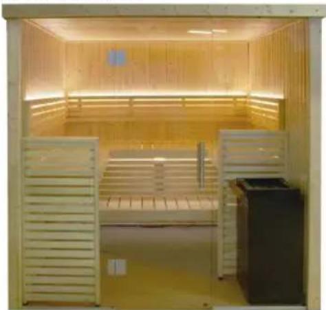
natural_image
Interior view of a wooden steamer cabin with slatted backrest and open counter (no visible text or symbols)Inhaltsverzeichnis
natural_image
Two diagrams showing a transparent rectangular object intersected by two lines, with no visible text or symbols.natural_image
Interior view of a simple indoor space with a small bench, a ladder, and a wall-mounted shelf (no visible text or symbols)Small
1635 x 1608 x 2020 mm
natural_image
Interior view of a wooden anxiety chamber with slatted bidders and a refrigerator (no visible text or symbols)Medium Large
S1620SV S2020SV
2060×1608×2020mm 2060×2033×2020mm

natural_image
Interior view of a wooden anxiety chamber with slatted back cover and side bays (no text or symbols visible)
natural_image
Interior view of a wooden steamer cabin with slatted panels and a refrigerator (no visible text or symbols)Table des matières
natural_image
Two diagrams showing a rectangular object intersected by two lines, one with diagonal lines and the other with a wavy line (no text or symbols)natural_image
Interior view of a room with a small bench, a ladder, and a wall-mounted shelf (no visible text or symbols)Small
1635 x 1608 x 2020 mm

natural_image
Interior view of a wooden anxiety chamber with white slatted panels and a black refrigerator (no visible text or symbols)Medium Large
S1620SV S2020SV
2060×1608×2020mm 2060×2033×2020mm
natural_image
Interior view of a wooden anxiety chamber with slatted windows and a black refrigerator (no visible text or symbols)
natural_image
Interior view of a wooden steamer cabin with slatted backrest and open storage unit (no visible text or symbols)Inhoudsopgave
1. Montagevoorbereiding 3
natural_image
Two diagrams showing a rectangular object intersected by two lines, one with diagonal lines and the other with a wavy line (no text or symbols)natural_image
Interior view of a room with a small bench, a ladder, and a wall-mounted shelf (no visible text or symbols)Small
1635 x 1608 x 2020 mm
natural_image
Interior view of a wooden anxiety chamber with white slatted panels and a black refrigerator (no visible text or symbols)Medium Large
S1620SV S2020SV
2060×1608×2020mm 2060×2033×2020mm

natural_image
Interior view of a wooden anxiety chamber with slatted panels and a black equipment unit (no visible text or symbols)
natural_image
Interior view of a wooden steamer cabin with slatted windows and a refrigerator (no visible text or symbols)PL
SPIS TREŚCI
natural_image
Two diagrams showing a rectangular object intersected by two lines, one with diagonal lines and the other with a wavy line (no text or symbols)natural_image
Interior view of a room with a small bench, a ladder, and a wall-mounted shelf (no visible text or symbols)Small
1635 x 1608 x 2020 mm

natural_image
Interior view of a modern indoor space with wooden furniture and storage units (no visible text or symbols)Medium Large
S1620SV S2020SV
2060×1608×2020mm 2060×2033×2020mm

natural_image
Interior view of a wooden anxiety chamber with slatted panels and a black refrigerator (no visible text or symbols)
natural_image
Interior view of a wooden steamer with slatted backrest and side b Arya, no visible text or symbolsRU
Содержание
natural_image
Two diagrams showing a rectangular object intersected by two lines, with no visible text or symbols.1.2. Уход и очистка
natural_image
Three-panel photo showing a wooden panel being cut, with close-up details of the same panel and screwdriver (no text or symbols visible)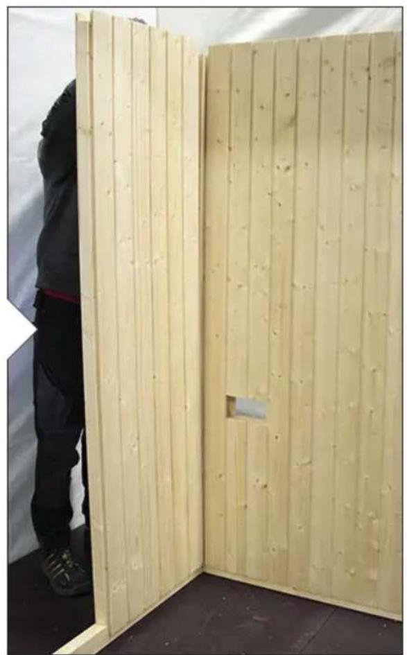
natural_image
Person standing beside a wooden panel with vertical slats, viewed from the side (no text or symbols visible)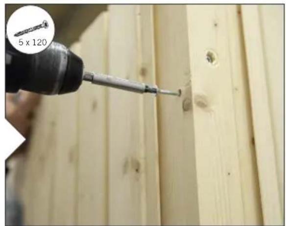
natural_image
Close-up of a hand using a screwdriver to cut wood panels, with a magnified inset showing a 5x120 ratio (no text or symbols on the diagram itself)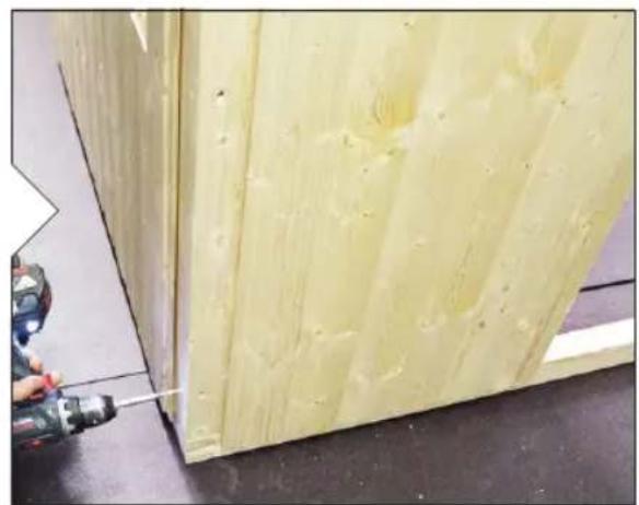
natural_image
Close-up of a yellow wooden panel with visible paint and a hand using a power tool (no text or symbols)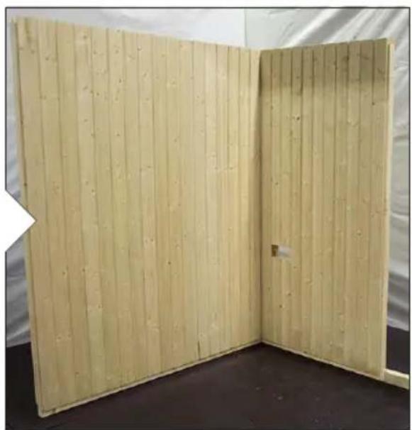
natural_image
Interior view of a room with vertical wooden panel panels and a small door, no visible text or symbols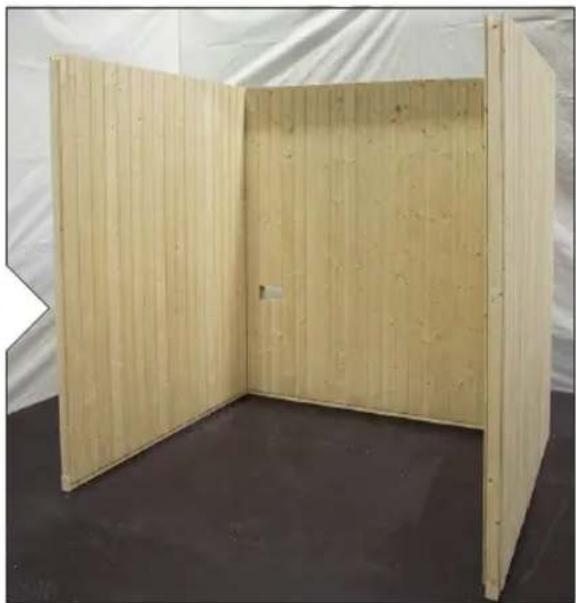
natural_image
Interior view of a simple wooden panel or enclosure with vertical slats, no text or symbols visible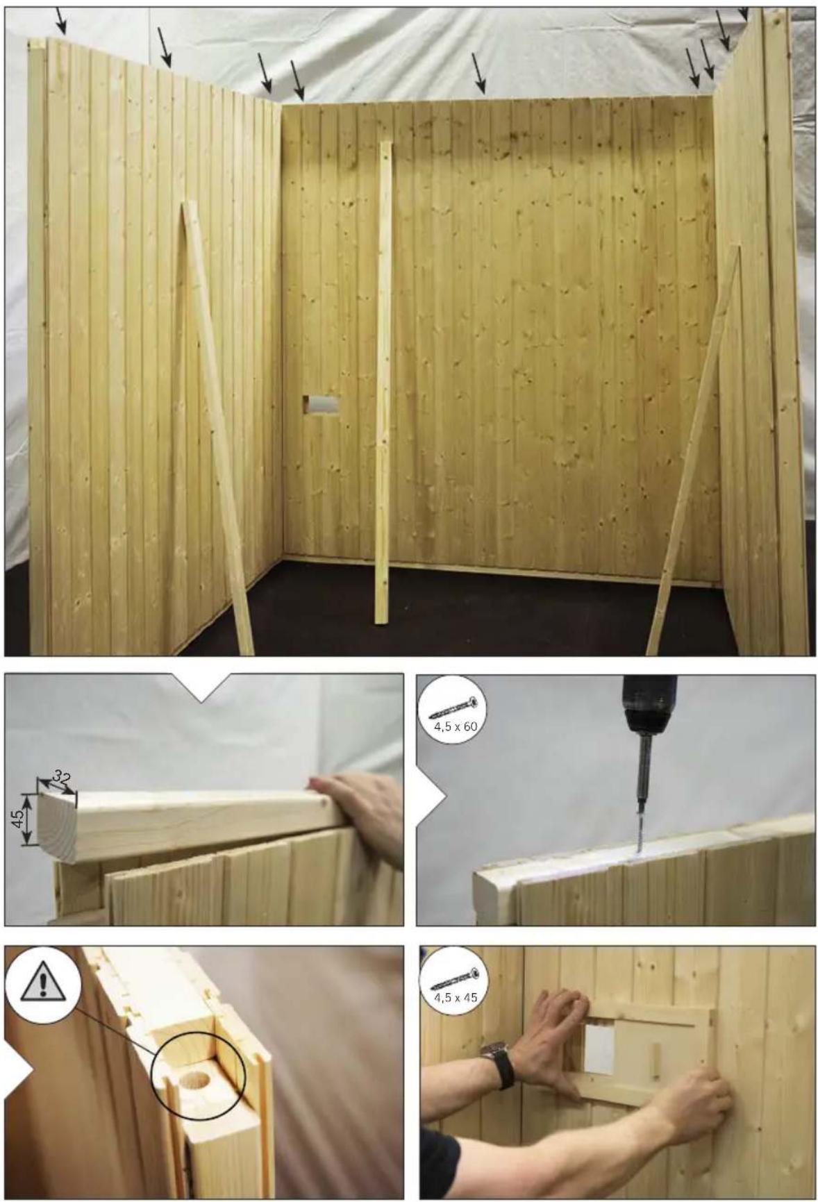
3.3.
natural_image
Two hands installing or adjusting a wooden structure under a white canopy (no text or symbols visible)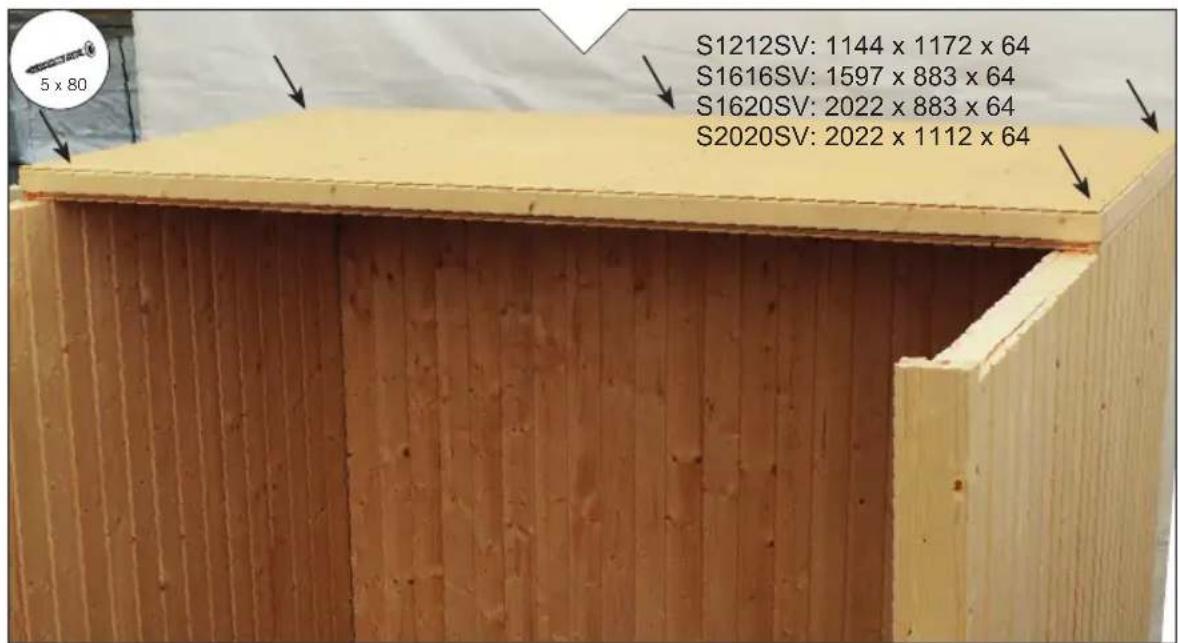
natural_image
Two-panel image showing a wooden post being cut with a screwdriver, and a close-up of the same post being finished (no text or symbols visible)3.4.

3.5.
natural_image
Close-up of a white metal bracket with green and black segments, against a blurred yellow background (no text or symbols visible)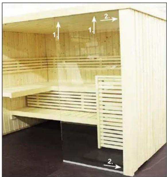
natural_image
Interior view of a wooden steamer cabin with slatted backrest and two directional arrows indicating movement (no text or symbols)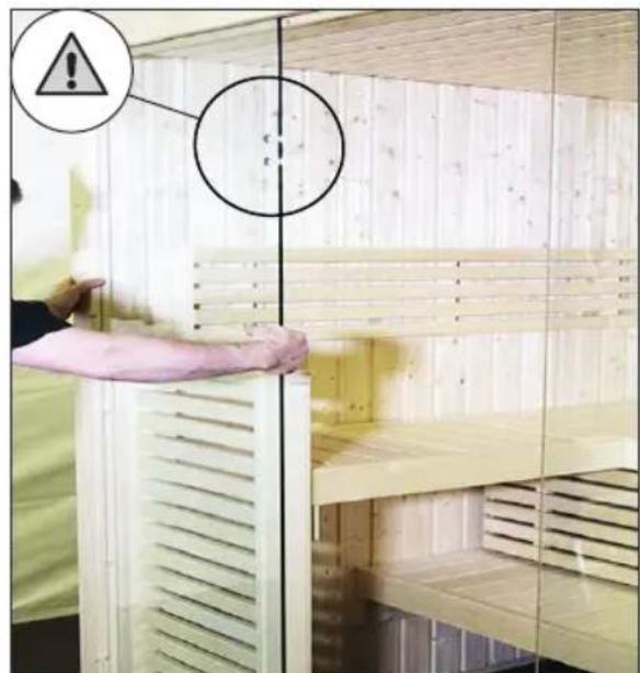
natural_image
Close-up of hands installing or adjusting a wooden window frame on a wooden door (no text or symbols visible)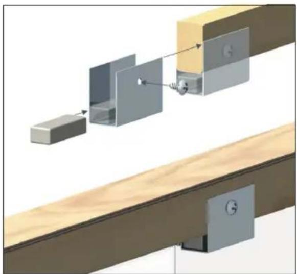
natural_image
Diagram of a mechanical assembly with labeled components, showing a shaft and housing assembly (no text or symbols present)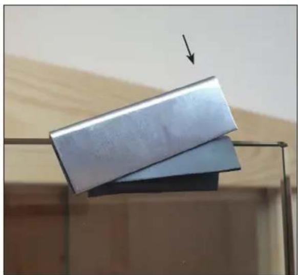
natural_image
Two metallic sheets stacked vertically on a metal frame, with an arrow pointing downward (no text or symbols visible)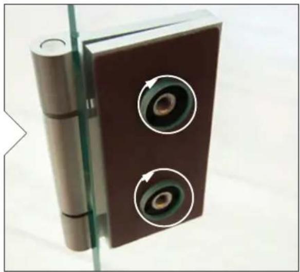
natural_image
Close-up of a brown mechanical component with two circular eye holes and a cylindrical handle, mounted against a plain background (no text or symbols visible)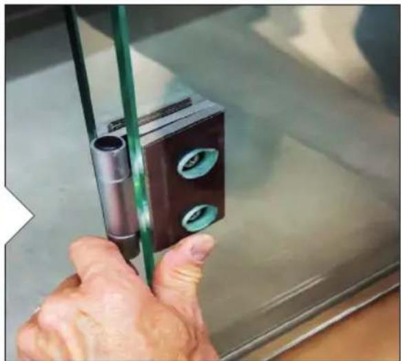
natural_image
Close-up of a hand holding a small mechanical component with green wires, no visible text or symbols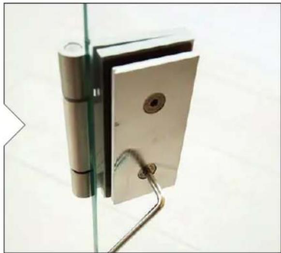
natural_image
Close-up of a metallic glass door hinge with metal clips and a handle, mounted on a stand (no text or symbols visible)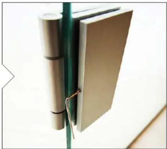
natural_image
Close-up of a metallic cylindrical object mounted on a green vertical pole, with a metal bracket attached (no visible text or symbols)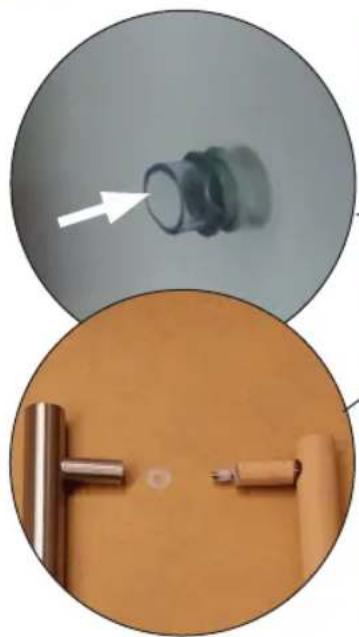
natural_image
Two circular images showing a cylindrical object with a white arrow pointing to it, and a close-up of a mechanical component with a tool (no text or symbols visible)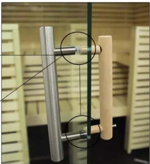
natural_image
Close-up of a mechanical device with metallic rods and wooden components, no visible text or symbols3.6.
3.7.
natural_image
Interior view of a wooden ceiling with hand gloves, showing wood grain and a hammer symbol (no text or symbols on main subject)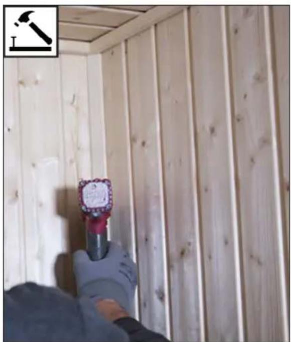
natural_image
Person holding a tool in front of wooden paneling, no visible text or symbols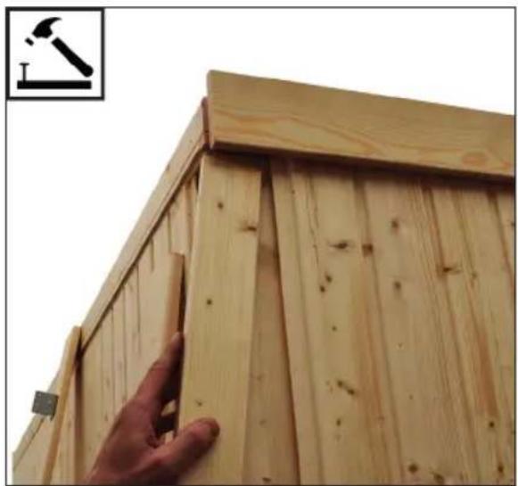
natural_image
Close-up of a wooden door frame with a hand touching the edge, showing wood grain and a hammer icon (no text or symbols)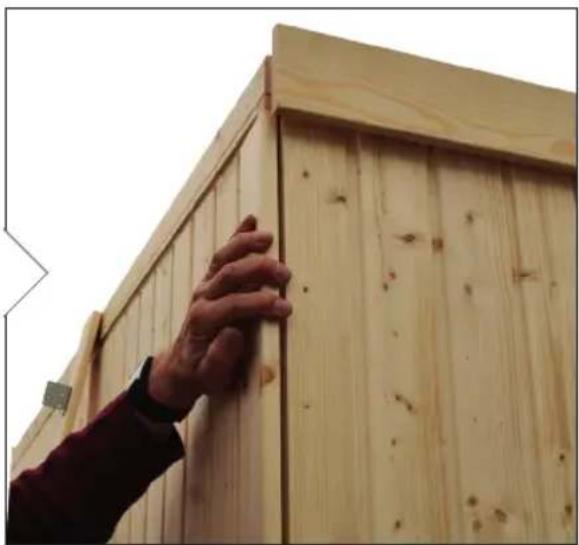
natural_image
Close-up of a person adjusting a wooden cabinet frame with visible grain and bolts (no text or symbols)3.8.
natural_image
Interior ceiling view showing a wooden floor installation with exposed electrical outlet and a dashed line indicating a measurement or alignment (no text or symbols visible)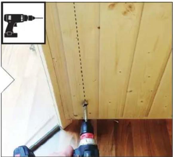
natural_image
Close-up of a wooden floor with a screwdriver inserted, showing a dashed line and a small inset image of a drill (no text or symbols)3.9.
natural_image
Top-down view of an electronic device with a cylindrical component mounted on a wooden surface (no text or symbols visible)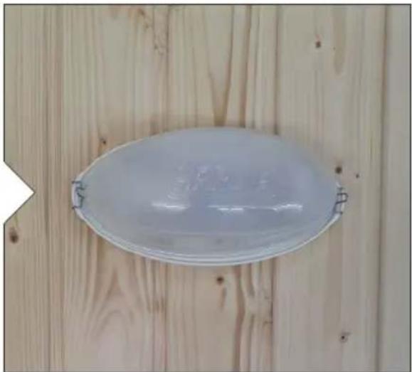
natural_image
White oval-shaped object mounted on a wooden wall, no visible text or symbols3.10.
NOTIZEN / APPUNTI / NOTES / NOTE / NOTITIES
NOTIZEN / APPUNTI / NOTES / NOTE / NOTITIES
Global:
www.harvia.fi
Tel. +358 207 464 000

www.sentioica.com
Tel. +43 7672 22 900-50
Central
Europ€


- Sisällys
- Table of Contents
- Preparing for installation 3
- Floor plan 10
- Assembling the cabin 12
- Illustrations for the parts list
- Assembly illustrations
- Preparing for installation
- Important note:
- Attention!
- Tools required
- Maintenance and cleaning
- Disposal
- Parts list for Mini S1212SV and Small S1616SV
- Parts list for Medium S1620SV and Large S2020SV
- Floor plan
- Variant View Mini S1212SV
- Variant View Small S1616SV
- Variant View Medium S1620SV
- Variant View Large S2020SV
- Assembling the cabin
- Assembling the base frame
- Assembling the cabin walls
- Assembling the roof elements
- Assembling the benches
- Assembling the glass elements
- Installing roof trim
- Mounting the cover slats
- Drill hole for electrical cable
- Mounting the light
- Installation KIT for heater installation at the bench foot
- Elementsauna
- VARIANT VIEW
- MONTAGEANLEITUNG
- Deutsch
- Inhaltsverzeichnis
- Table des matières
- Inhoudsopgave
- Montagevoorbereiding 3
- SPIS TREŚCI
- Содержание
- Уход и очистка
- NOTIZEN / APPUNTI / NOTES / NOTE / NOTITIES
Brand : HARVIA
Model : Variant View S1620SV
Category : Sauna