
286310 - Pasta machine BARTSCHER - Free user manual and instructions
Find the device manual for free 286310 BARTSCHER in PDF.
| Product type | Professional pasta machine with integrated cooking |
| Housing material | 18/10 stainless steel |
| Cooking tray material | Stainless steel resistant to salt water and starch |
| Heating type | Stainless steel tubular burner (gas) or sheathed resistors (electric) |
| Rated power (gas) | 8.70 kW (1/2 module) / 13.30 kW (3/4 module) / 17.40 kW (1 module) |
| Power supply | 230 V / 50 Hz (electric models) |
| Compatible gas type | G20 (methane), G25, G30 (butane), G31 (propane) |
| Gas supply pressure | 20 mbar (G20), 25 mbar (G25), 30/37 mbar (G30/G31) |
| Gas safety | Gas valve with thermocouple and pilot light |
| Electrical safety | Manual reset thermostat, switch with 3 mm opening |
| Equipotential connection | Ground terminal with specific label |
| Power adjustment | Rotary control from minimum to maximum (4 positions for electric) |
| Functions | Cooking, keep warm, start cooking |
| Cleaning | Warm water and mild detergent, no direct jet or abrasives |
| Maintenance | Annual check by qualified personnel (seals, burners, cables) |
| Original spare parts | Mandatory use of parts supplied by the manufacturer |
| Repairability | Interventions reserved for an authorized technician |
| Installation | By a qualified installer, compliance with local standards (gas, electricity, ventilation) |
| Use | Professional catering |
| Warranty | Compliant with European directives (LVD, EMC, gas, machinery) |
Frequently Asked Questions - 286310 BARTSCHER
User questions about 286310 BARTSCHER
0 question about this device. Answer the ones you know or ask your own.
Ask a new question about this device
Download the instructions for your Pasta machine in PDF format for free! Find your manual 286310 - BARTSCHER and take your electronic device back in hand. On this page are published all the documents necessary for the use of your device. 286310 by BARTSCHER.
USER MANUAL 286310 BARTSCHER


2853051
(G=Gas;
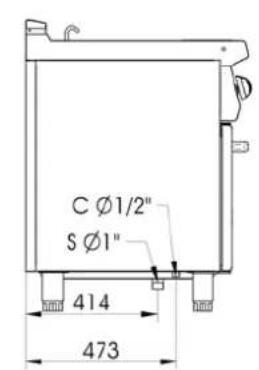
C= Carico acqua \ Remplissage d'eau \ Water filling \ Wasser anfüllen;
S= Scarico acqua \ Evacuer l'eau \ Water emptying \ Wasser entleeren)
Fig. - Abb. 1: Dimensioni \ Dimensions \ Floor space dimensions \ Raumbedarfsmasse


2853061
(G=Gas;
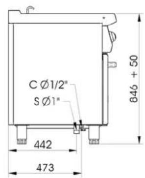
C= Carico acqua \ Remplissage d'eau \ Water filling \ Wasser anfüllen;
S= Scarico acqua \ Évacuer l'eau \ Water emptying \ Wasser entleeren)
Fig. - Abb. 2: Dimensioni \ Dimensions \ Floor space dimensions \ Raumbedarfsmasse


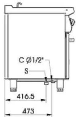
2853101
(G=Gas;
C= Carico acqua \ Remplissage d'eau \ Water filling \ Wasser anfüllen;
S= Scarico acqua \ Évacuer l'eau \ Water emptying \ Wasser entleeren)
Fig. - Abb. 3: Dimensioni \ Dimensions \ Floor space dimensions \ Raumbedarfsmasse


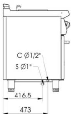
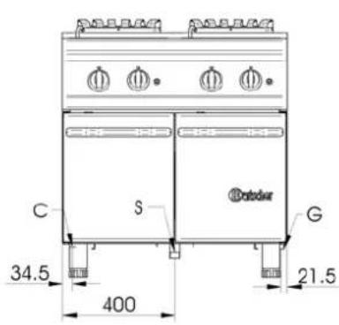
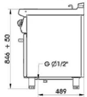
286305
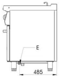
(E= elettrico \ électrique \ electric\ Elektrisch
C= Carico acqua \ Remplissage d'eau \ Water filling \ Wasser anfüllen;
S= Scarico acqua \ Évacuer l'eau \ Water emptying \ Wasser entleeren)
Fig. - Abb. 4: Dimensioni \ Dimensions \ Floor space dimensions \ Raumbedarfsmasse


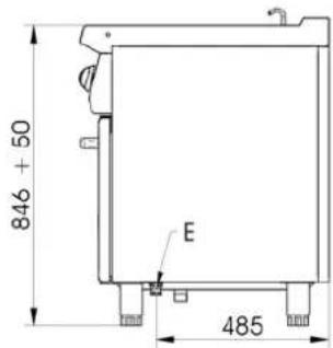
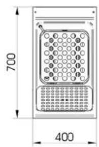
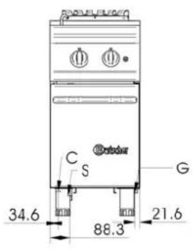
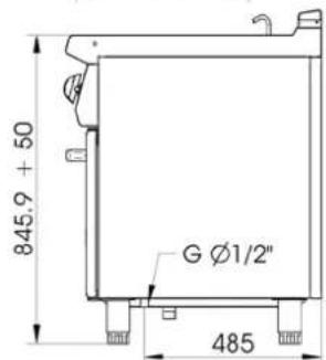
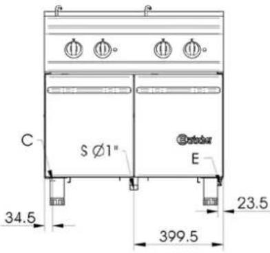
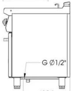
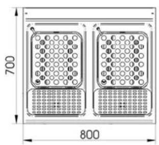
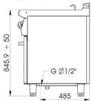
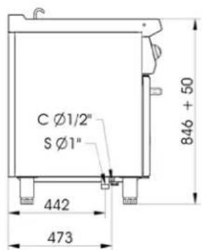
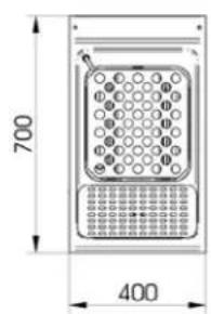
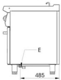
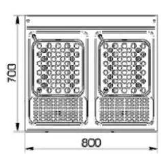
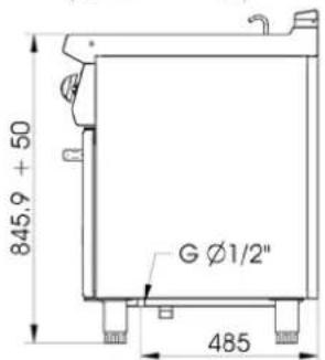
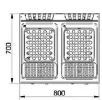
286310
(E= elettrico \ électrique \ electric\ Elektrisch
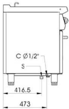
C= Carico acqua \ Remplissage d'eau \ Water filling \ Wasser anfüllen;
S= Scarico acqua \ Évacuer l'eau \ Water emptying \ Wasser entleeren)
Fig. - Abb. 5: Dimensioni \ Dimensions \ Floor space dimensions \ Raumbedarfsmasse
| CAT/KAT | GAS/GAZ | G30 | G31 | G20 | G25 | G25.1 | G110 | G120 | Made in E.U. | ||
| I_2H | p mbar - - 20 - - - - | LV | |||||||||
| I_3P | p mbar - 37 - - - - - | IS | |||||||||
| I_3B/P | p mbar 28-30 28-30 | CY MT | |||||||||
| II_2E+3P | p mbar - 37 20 25 - - - | LU | |||||||||
| II_2E+3+ | p mbar 28-30 37 20 25 - - - | FR BE | |||||||||
| CE XXXXNo | II_2H3+ | p mbar 30 37 20 - - - - | IT PT GR GB | ||||||||
| II_2H3+ | p mbar 28 37 20 - - - - | ES IE CH | |||||||||
| TIPO/TYPE A | II_2E3P | p mbar - 37 20 - - - - | PL | ||||||||
| MOD.ART.N°. | II_2ELL3B/P | p mbar 50 50 20 20 - - - | DE | ||||||||
| II_2H3B/P | p mbar 50 50 20 - - - - | AT CH CZ SK | |||||||||
| II_2H3B/P | p mbar 28-30 28-30 20 - - - - | FI LT BG | |||||||||
| kW B Qn m^3/h Ckg/h D | II_2H3B/P | p mbar 28-30 28-30 20 - - - - | NO SK RO | ||||||||
| II_2H3B/P | p mbar 28-30 28-30 20 - - - - | EE SI HR TR | |||||||||
| II_2HS3B/P | p mbar 28-30 28-30 25 - 25 - - | HU | |||||||||
| kW E V~ FHz G | II_2L3B/P | p mbar 30 30 - 25 - - - | NL | ||||||||
| III_1ab2H3B/P | p mbar 28-30 28-30 20 - - 8 8 | SE | |||||||||
| III_1a2H3B/P | p mbar 28-30 28-30 20 - - 8 - | DK | |||||||||
| Predisposto a gas-Prévu pour gaz-Voreinstellung für Gas-Predisposto a gás-Voorzien van gas-Set for use with gas-Preparado para gas-Ment for á brukes med gass-Avsett för att användas med gas-Tarkoitettu käytettäväksi kaasulla-Forberedt til brug afgas-Πρατομασμένογια λεπαργία με αέριο- Zařízeni na plyn - Toimib gaasi pôhjal - A berendezés gáz használatáraelőkészített – Sagatavota darbam ar gáz – Przysposobione na gas – Numatyta dumjos - Nastavený na plyn –Pripravljeno za plin | G20 20mbar (H) | ||||||||||

Figg. – Abb. 11, 12: Sostituzione del By-Pass \ Changement du by-pass \ Substituting the By-Pass \ Austausch des By-Pass


natural_image
Line drawing of a kitchen appliance with two doors, three fans, and a top-mounted stove (no text or symbols)
natural_image
Line drawing of a double boiler cabinet with four side outlets and control switches (no text or labels)Fig. - Abb. 17: Carico vasca \ Remplissage de la marmite\ Filling the tub \ Anfüllen des Beckens
Fig. - Abb. 16 : Istruzioni uso (Cuocipasta elettrico) \ Instructions d'utilisation (Marmites électrique) \ Instruction for use (Electirc pasta cookers) \ Bedienungsanleitungen (Elektrische nudelkocher)
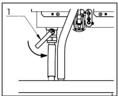

Fig. - Abb. 18: Scarico vasca\ Vidage de la marmite \ Emptying the tub \Entleeren des Beckens

Fig. – Abb. 20: : Sostituzione componenti elettrici di comando\ Remplacement composants électriques de contrôle \ Replacement of electric components\ Ersetzen von elektrischen Komponenten
INSTALLATION, USE AND MAINTENANCE


2853051
(G=Gas;
C= Carico acqua \ Remplissage d'eau \ Water filling \ Wasser anfüllen;
S= Scarico acqua \ Evacuer l'eau \ Water emptying \ Wasser entleeren)
Fig. - Abb. 1: Dimensioni \ Dimensions \ Floor space dimensions \ Raumbedarfsmasse


2853061
(G=Gas;
C= Carico acqua \ Remplissage d'eau \ Water filling \ Wasser anfüllen;
S= Scarico acqua \ Évacuer l'eau \ Water emptying \ Wasser entleeren)
Fig. - Abb. 2: Dimensioni \ Dimensions \ Floor space dimensions \ Raumbedarfsmasse


2853101
(G=Gas;
C= Carico acqua \ Remplissage d'eau \ Water filling \ Wasser anfüllen;
S= Scarico acqua \ Évacuer l'eau \ Water emptying \ Wasser entleeren)
Fig. - Abb. 3: Dimensioni \ Dimensions \ Floor space dimensions \ Raumbedarfsmasse


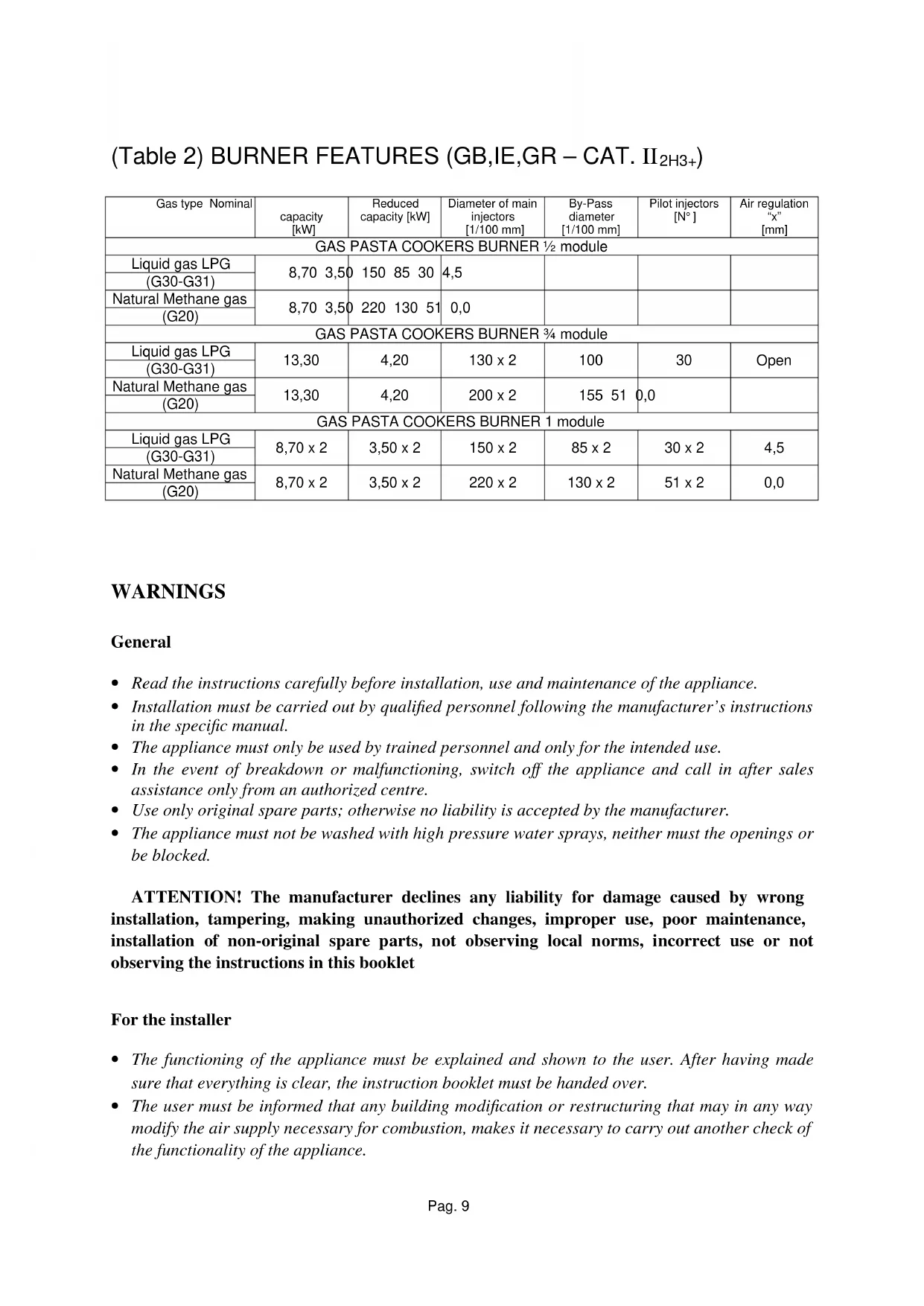
286305
(E= elettrico \ électrique \ electric\ Elektrisch
C= Carico acqua \ Remplissage d'eau \ Water filling \ Wasser anfüllen;
S= Scarico acqua \ Évacuer l'eau \ Water emptying \ Wasser entleeren)
Fig. - Abb. 4: Dimensioni \ Dimensions \ Floor space dimensions \ Raumbedarfsmasse


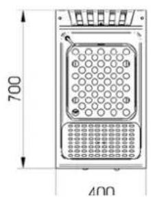
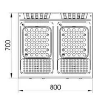
286310
(E= elettrico \ électrique \ electric\ Elektrisch
C= Carico acqua \ Remplissage d'eau \ Water filling \ Wasser anfüllen;
S= Scarico acqua \ Évacuer l'eau \ Water emptying \ Wasser entleeren)
Fig. - Abb. 5: Dimensioni \ Dimensions \ Floor space dimensions \ Raumbedarfsmasse
| CAT/KAT | GAS/GAZ | G30 | G31 | G20 | G25 | G25.1 | G110 | G120 | Made in E.U. | ||
| I_2H | p mbar - - 20 - - - - | LV | |||||||||
| I_3P | p mbar - 37 - - - - - | IS | |||||||||
| I_3B/P | p mbar 28-30 28-30 | CY MT | |||||||||
| II_2E+3P | p mbar - 37 20 25 - - - | LU | |||||||||
| II_2E+3+ | p mbar 28-30 37 20 25 - - - | FR BE | |||||||||
| CE XXXXNo | II_2H3+ | p mbar 30 37 20 - - - - | IT PT GR GB | ||||||||
| II_2H3+ | p mbar 28 37 20 - - - - | ES IE CH | |||||||||
| TIPO/TYPE A | II_2E3P | p mbar - 37 20 - - - - | PL | ||||||||
| MOD.ART.N°. | II_2ELL3B/P | p mbar 50 50 20 20 - - - | DE | ||||||||
| II_2H3B/P | p mbar 50 50 20 - - - - | AT CH CZ SK | |||||||||
| II_2H3B/P | p mbar 28-30 28-30 20 - - - - | FI LT BG | |||||||||
| kW B Qn m^3/h Ckg/h D | II_2H3B/P | p mbar 28-30 28-30 20 - - - - | NO SK RO | ||||||||
| II_2H3B/P | p mbar 28-30 28-30 20 - - - - | EE SI HR TR | |||||||||
| II_2HS3B/P | p mbar 28-30 28-30 25 - 25 - - | HU | |||||||||
| kW E V~ FHz G | II_2L3B/P | p mbar 30 30 - 25 - - - | NL | ||||||||
| III_1ab2H3B/P | p mbar 28-30 28-30 20 - - 8 8 | SE | |||||||||
| III_1a2H3B/P | p mbar 28-30 28-30 20 - - 8 - | DK | |||||||||
| Predisposto a gas-Prévu pour gaz-Voreinstellung für Gas-Predisposto a gás-Voorzien van gas-Set for use with gas-Preparado para gas-Ment for á brukes med gass-Avsett för att användas med gas-Tarkoitettu käytettäväksi kaasulla-Forberedt til brug afgas-Πρατομασμένογια λεπαργία με αέριο- Zařízení na plyn - Toimib gaasi pôhjal - A berendezés gáz használatáraelőkészített – Sagatavota darbam ar gáz – Przysposobione na gas – Numatyta dumjos - Nastavený na plyn –Pripravljeno za plin | G20 20mbar (H) | ||||||||||

Figg. – Abb. 11, 12: Sostituzione del By-Pass \ Changement du by-pass \ Substituting the By-Pass \ Austausch des By-Pass

natural_image
Line drawing of a kitchen appliance with two doors, three fans, and a top-mounted stove (no text or symbols)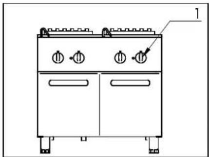
natural_image
Line drawing of a double boiler cabinet with four side outlets and control knobs (no text or symbols)Fig. - Abb. 17: Carico vasca \ Remplissage de la marmite\ Filling the tub \ Anfüllen des Beckens
Fig. - Abb. 16 : Istruzioni uso (Cuocipasta elettrico) \ Instructions d'utilisation (Marmites électrique) \ Instruction for use (Electirc pasta cookers) \ Bedienungsanleitungen (Elektrische nudelkocher)


Fig. - Abb. 18: Scarico vasca\ Vidage de la marmite \ Emptying the tub \Entleeren des Beckens
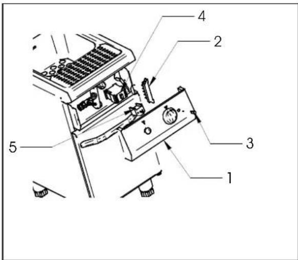
Fig. – Abb. 20: : Sostituzione componenti elettrici di comando\ Remplacement composants électriques de contrôle \ Replacement of electric components\ Ersetzen von elektrischen Komponenten
(Table 1) TECHNICAL FEATURES (GB-IE-GR-FI-NO-NL-SE-DK-LV-IS-CY-MT-PL-CZ-SK-LT-BG-RO-EE-SI-HR-TR-HU)
| Model | Description | Dimensions LxPxH [mm] | Gas Output (B) [Kw] | Type (A) | Consumption LPG (G30) (D) [Kg/h] | Consumption Natural Methane (G20) (C) [m3/h] | TOWN GAS Consumption (G110) (C) [m3/h] | Air for comb. [m3/h] | Gas fitting | Electric Output. (E) [Kw] | Tensions (F) [V] | Freq. (G) [Hz] | Cable Type H07 RN-F [mm2] | Water Supply Pressure MAX [kPa] | Water fitting |
| 2853051 | Gas Pasta cooker 1⁄2 module 400x700x845 8,7 A1 0,68 | 60 | 0,9206 | 17,4 17,4 | UNI-ISO 7/1 R 1⁄2 | - - - - 300 | UNI-ISO 7/1 R 1⁄2 | ||||||||
| 2853061 | Gas Pasta cooker 3⁄4 module 600x700x845 13,7 | A1 1,0961 | 1,470 | 27,8 27,8 | UNI-ISO 7/1 R 1⁄2 | - - - - 300 | UNI-ISO 7/1 R 1⁄2 | ||||||||
| 2853101 | Gas pasta cooker 1 module 800x700x845 17,4 | A1 1,3721 | 1,841 | 34,8 34,8 | UNI-ISO 7/1 R 1⁄2 | - - - - 300 | UNI-ISO 7/1 R 1⁄2 | ||||||||
| 286305 | Electric pasta cooker 1⁄2 module | 400x700x845 | - | - | - | - | - | - | 7 | 230 3 – 400 3N | 50 | 4 x2,5 – 5 x 1.5 | 300 | UNI-ISO 7/1 R 1⁄2 | |
| 286310 | Electric pasta cooker 1 module | 800x700x845 | - | - | - | - | - | - | 14 | 230 3 – 400 3N | 50 | 4 x 6 – 5 x 2,5 | 300 | UNI-ISO 7/1 R 1⁄2 |
(Table 2) BURNER FEATURES (GB, IE, GR - CAT. II _2H3+ )
| Gas type Nominal | capacity [kW] | Reduced capacity [kW] | Diameter of main injectors [1/100 mm] | By-Pass diameter [1/100 mm] | Pilot injectors [N°] | Air regulation “x” [mm] |
| GAS PASTA COOKERS BURNER 1⁄2 module | ||||||
| Liquid gas LPG (G30-G31) | 8,70 3,50 | 150 85 30 | 4,5 | |||
| Natural Methane gas (G20) | 8,70 3,50 | 220 130 51 | 0,0 | |||
| GAS PASTA COOKERS BURNER 3⁄4 module | ||||||
| Liquid gas LPG (G30-G31) | 13,30 | 4,20 | 130 x 2 | 100 | 30 | Open |
| Natural Methane gas (G20) | 13,30 | 4,20 | 200 x 2 | 155 51 0,0 | ||
| GAS PASTA COOKERS BURNER 1 module | ||||||
| Liquid gas LPG (G30-G31) | 8,70 x 2 | 3,50 x 2 | 150 x 2 | 85 x 2 | 30 x 2 | 4,5 |
| Natural Methane gas (G20) | 8,70 x 2 | 3,50 x 2 | 220 x 2 | 130 x 2 | 51 x 2 | 0,0 |
WARNINGS
General
- Read the instructions carefully before installation, use and maintenance of the appliance.
- Installation must be carried out by qualified personnel following the manufacturer's instructions in the specific manual.
- The appliance must only be used by trained personnel and only for the intended use.
- In the event of breakdown or malfunctioning, switch off the appliance and call in after sales assistance only from an authorized centre.
- Use only original spare parts; otherwise no liability is accepted by the manufacturer.
- The appliance must not be washed with high pressure water sprays, neither must the openings or be blocked.
ATTENTION! The manufacturer declines any liability for damage caused by wrong installation, tampering, making unauthorized changes, improper use, poor maintenance, installation of non-original spare parts, not observing local norms, incorrect use or not observing the instructions in this booklet
For the installer
- The functioning of the appliance must be explained and shown to the user. After having made sure that everything is clear, the instruction booklet must be handed over.
- The user must be informed that any building modification or restructuring that may in any way modify the air supply necessary for combustion, makes it necessary to carry out another check of the functionality of the appliance.
TECHNICAL FEATURES
The following instructions for starting up and functioning refer to gas and mixed appliances belonging to category I_3B/P , _2H3+ , _2H3B/P , _2L3B/P , _1ab2H3B/P , _1a2H3B/P with a power pressure for Butane (G30) of 28/30mbar, for propane (G31) of 30/37 mbar, for Methane (Natural Gas) (G20-G25) of 20/25 mbar and for town gases (G110 – G120) of 8 mbar. The data plate (fig. 6 – pag. 4) with all the information to refer to regarding the appliance, is situated inside the right or left side of the control panel, depending on the model.
The appliances have been checked in accordance with the European norms below.
2006/95/CE - Low Tension (LVD)
CEE 2004/108 - Electromagnetic Compatibility (EMC)
90/396/EEC - Gas Appliances
98/37/EC - Appliance to the directives
And the particular reference norms.
Declaration of compliance
The manufacturer declares that the appliances of their production are compliant with the above mentioned EEC norms and requires that installation be done observing the norms in force, particularly regarding the system for letting out fumes and air exchange.
DESCRIPTION OF APPLIANCES
Gas Appliances
Sturdy structure in steel placed on four feet which make it possible to regulate the height in the version with cabinet.
The outer finishing is stainless steel with Chrome-Nickel 18-10. It has a safety gas cock, enabling regulation of the output from maximum to minimum, safety is ensured by a thermocouple which is kept active by the flame of the pilot burner.
The tub is made entirely in stainless steel, resistant to salted water and to starch. The chamber is heated by means of a stainless steel tubular burner, suitable for proper functioning at the high temperatures to which it is exposed.
Electric Appliance
Sturdy structure in steel placed on four feet which make it possible to regulate the height in the version with cabinet. The outer finishing is stainless steel with Chrome-Nickel 18-10.
Each tub is provided with a selector, which makes it possible to regulate the power from maximum to minimum in four positions; safety is ensured by a manually activated thermostat.
The tub is made entirely in stainless steel, resistant to salted water and starch.
The heating is done by means of elements protected with a sheath, resistant to salted water.
PROVISIONS FOR INSTALLATION
It is advisable to install the appliance in a well ventilated room or under an extractor hood. The appliance may be installed as a single unit or together with others. In both cases, if it is installed near a wall of inflammable material, a minimum distance of 100mm from the side and back walls must be observed. In the event that it is not possible to observe this distance, protective measures must be taken (e.g. use of sheets of refractory material) which ensure that the temperature of the walls is within the established safety limits.
Installation
Installation operations, gas or voltage conversions to other than the original, starting up the installation or appliance, ventilation, letting out fumes, and maintenance must be done following the manufacturer's instructions and observing the norms in force, by qualified personnel, in compliance with the following rules (GB):
■ Gas Safety (Installation and Use) Regulations, 1984
■ Health and Safety at Work Act, 1974
■ Codes of Practice, BS6173, 1982
■ The Building Regulations, 1985
■ The Building Standards Regulations, 1981
For others countries apply to the relevant local rules:
Gas board rules
■ Building regulations and local fire prevention rules.
■ Safety norms in force
■ Rules of the Gas supplying company
■ The Electrical Norms in force
■ The Fire Brigade rules
Fumes evacuation
The appliances are all classified Type "A1".
It is not necessary to connect this type of appliance directly to an evacuation pipe for combustion products. The products of combustion, however, must be directed into suitable hoods or similar devices, connected to a reliably efficient chimney, otherwise directly outside. The use of an extractor fan connected directly to external environment with a capacity no lower than what is stated in table 1. This value must be increased with the air exchange necessary for the well-being of the operators, in accordance with the norms in force. (approximately a total of 35 m^-3/h per KW of gas output installed).
INSTALLATION
Preliminary operations
Remove the appliance from the packaging, ascertaining that it is intact and, if in doubt, do not use it but call in professionally qualified personnel. After having verified that the appliance is in good condition, the protective film may be removed. Carefully clean the external parts of the appliance with warm water and detergent using a cloth to remove all remaining residues and then dry it with a soft cloth. If there are still traces of glue residues, remove them by using a suitable solvent (e.g. acetone): Under no circumstances must abrasive substances be used. After having been put into place, the appliance must be levelled by regulating the adjustable feet.
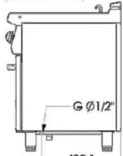
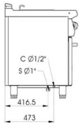
Gas Connection
Before connecting the appliance, it is necessary to check that the type of gas available corresponds to the type of gas the appliance has been set for. In the event that they do not correspond, it is necessary to proceed as described in the paragraph “Functioning with gas different from the setting”. The connection to the threaded coupling, with a diameter of 12 inch, situated on the bottom of the appliance, may be fixed or mobile using a compliant rapid pipe fitting. If flexible piping is used, this must be in stainless steel and compliant with the norm. All the seals on the junction threads must be in guaranteed materials certified for use with gas. Before the installation of each single appliance it is necessary to install a cutoff cock for rapid interruption of the gas supply, placed in an easily accessible position in such a way as to make it possible to turn off the gas supply when the appliance is not being used. When the connection has been completed, the tightness must be checked by using a leak-finder spray.
Electric connection
Before connecting the appliance, it is necessary to check that the voltage of the power supply available corresponds to the voltage the appliance has been set for. In the event that they do not correspond, it is necessary to modify the connection as shown in the electric diagram, if voltage change is provided for. The junction boxes are situated behind the control panel of the top, is accessible by unscrewing the screws which fix the panel and removing it. Furthermore, the efficiency of the earth connection must be checked, and also that the earth conductor on the connecting side is longer than the other conductors, and that the connecting cable has a wire bunch adequate for the power absorbed by the appliance and is at least type H05 RN-F. In accordance with international rules, before installing the appliance a unipolar device must be installed with a contacts opening of at least 3mm which must not interrupt the YELLOW-GREEN earth wire. The device must be installed near the appliance, it must be approved and have adequate capacity for the absorption of the appliance (see technical features).
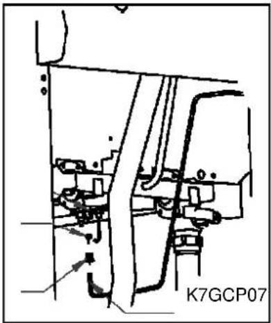
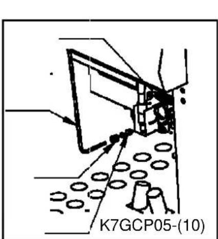
The appliance must be connected to the EQUIPOTENTIAL system. The connector is situated near the end of the electric cable inlet and is identified by a label (fig. 8 – pag. 5)
Connection to the water mains
Connect the water inlet pipe to the mains, following the rules stipulated by the norms in force.
Drainage connection
The drainage pipe must not be connected directly to a common drain, but positioned over a reservoir, at a distance which does not allow it come into contact with the sides of the reservoir or with the water inside it, in order to avoid contaminating the food in the tub.
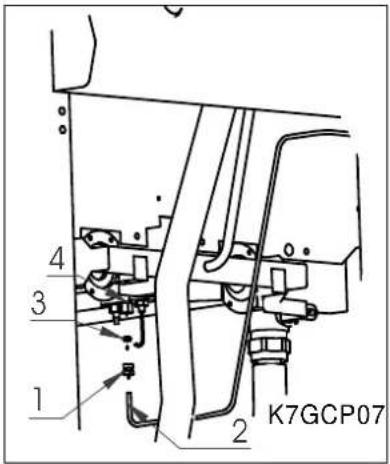
Checking gas tightness and pressure (fig. 9 - pag. 5).
Before proceeding to check the pressure, it is necessary to check the tightness of the gas installation up to the nozzle with a leak-finder spray to ensure that no damage has been done to the appliance during transportation. Then it is possible to proceed with checking the inlet pressure, which is done by means of a gauge for liquids, either a "U" gauge or an electronic gauge with a minimum definition of 0,1 mbar. To carry out the reading, the screw (1) must be removed from the pressure outlet (2) and the rubber pipe of the gauge connected. Open the gas supply valve of the appliance, check the pressure output and close the valve. Remove the pipe of the gauge and put back the screws correctly into the pressure outlet. The pressure valve must be within the minimum and maximum values shown below:
| Type of gas | P_n [mbar] | P_min [mbar] | P_MAX [mbar] |
| G20 (Methane) 20 | 17 | 25 | |
| G25 (Methane) 25 | 20 | 30 | |
| G30 (Butane) | 30 | 20 | 35 |
| G31 (Propane) | 37 | 25 | 45 |
| G110/G120 (town gas) | 8 | 6 | 15 |
If the pressure reading is not within the limits of the table, find out the cause. After solving the problem, check the pressure again.
Checking the power
Normally, it is sufficient to check that the nozzles installed are the right ones and that the burners function properly. If desired, further check the power absorbed by using the "Volumetric Method". With the help of a chronometer and a counter, it is possible to read the volume of gas output to the appliance in time units. The right comparison volume [E] can be obtained with the formula shown below in litres per hour (l/h) or in litres per minutes (l/min), by dividing the nominal and minimum outputs (power) shown in the table of burner features for the lowest heat capacity of the type of gas foreseen for use with the appliance. This value can be found in the norm tables or can be provided by the local gas supply company.
$$ E = \frac {\text { Output (Power) }}{\text { Heat Output }} $$
The reading must be done when the appliance is already in function.
Checking pilot burner
Check the flame of the pilot burner, which must be neither too short nor too high but must lap the thermocouple and have a sharp form; otherwise, it is necessary to check the size of the nozzle depending on the pilot version, as specified in the following paragraphs.
Checking regulation of primary air
All the main burners are provided with primary air regulation. Checking must be done observing the values shown in the air regulation column of the burner features table. To regulate the primary air, proceed as illustrated in the following paragraphs.
ATTENTION! All the parts, protected and sealed by manufacturer may not be regulated by the installer if not specifically indicated.
REGULATIONS AND SUBSTITUTION FOR USING DIFFERENT GAS THAN THE TYPE PROVIDED FOR
Functioning with different gas than the type provided for
When changing to another type of gas it is necessary to substitute the nozzle in the main burners and in the pilot burner, following the indications given in the following paragraphs. The type of nozzle to install can be found in table 2 (pag. 9). The nozzles for the main burner, marked with the relative diameter in hundredths, and the ones for the pilot burner, marked with a number, can be found in a transparent packet attached to the instruction booklet.
When the conversion is completed, check the tightness of the pipe fittings and also that the ignition and functioning of both pilot burner and main burner, at both minimum and maximum, are correct. It may be necessary to check the output (power).
Substituting the burner nozzle (fig.10 - pag. 5)
To substitute the burner nozzle, it is necessary to open the door of the compartment. After doing this, the screw which blocks the regulation of primary air must be loosened (1) and regulated until completely open (2); the nozzle must be unscrewed (3) with a spanner and substituted with an appropriate nozzle for the type of gas used, shown in table 2- (pag. 9). This nozzle must be assembled, tightening well and it is then necessary to proceed by regulating the primary air, as indicated in the next paragraph. When all this is done, replace the parts previously removed and proceed to regulate the primary air, as indicated in the next paragraph.
Regulating the primary air of the burner (fig. 10 - pag. 5)
After having substituted the burner nozzle, it is necessary to proceed by regulating the primary air: loosen the screw which fixes the regulating stirrup (1), bring value "x" to the correct measurement, referring to table 2 (pag. 9) tighten the screw (2) and check the accuracy of value "x".
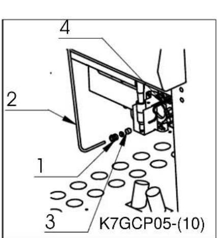
Substituting the By-Pass (fig. 11, 12 - pag. 5)
To substitute the by-pass, the knob (1) and the control panel (2) must be removed. When the work area has been cleared, unscrew the by-pass (3) with a screwdriver and substitute it with the suitable for the type of gas to be used, shown in table 2 (pag. 9). Reassemble the by-pass and tighten it well.
Put back the control panel and the knobs.
Substituting the pilot burner nozzle (fig. 13, 14 - pag. 6)
To substitute the pilot burner nozzle, it is necessary to open the door of the compartment, unscrew the fitting (1) which fixes the gas supply pipe of the pilot (2) and remove the nozzle (3). This must be substituted with an appropriate nozzle for the type of gas used, shown in table 2 (pag. 9).
Assemble the new nozzle, replace the pipe and tighten the fitting fully.
INSTRUCTIONS FOR USE
To light the burners of the pasta cooker, proceed in the following way:
- turn the knob (1) from the off position ● into the on position ★;
- press down fully;
- push the button of the piezoelectric lighter (2) *o light the pilot burner;
- keep the knob pressed down until the thermocouple heats up, keeping the pilot lit; this can be checked through the opening in the combustion chamber;
- light the main burner as desired, going from maximum ♦ to minimum♦.
To put out the main burner, it is necessary to turn the knob to the right into the on position ★ , to put out also the pilot, turn the knob again, into the off position ●.
Electric pasta cooker (fig. 16 - pag. 6)
To heat a tub of the pasta cooker, proceed in the following way::
- turn the knob (1) into the desired position. The green light will light up, showing that the heating elements are on.
It is advisable to regulate the element to the maximum temperature in order to reach the desired temperature right away, and to leave it in this position for a few minutes; then turn the knob into the position desired.
To turn off the pasta cooker, turn the knob back into position 0.
| Position [N°] | Use |
| 0 Pasta cooker off | |
| 1 Maintaining temperature | |
| 2 Cooking | |
| 3 Starting cooking | |
First of all, check that the drainage tap, situated inside the appliance under the combustion chamber, is closed tightly. After that, turn the water filling knob (1) in anti-clockwise direction; fill the tub up to the level mark. During the cooking, it is advisable to leave the tap turned slightly on, in order to keep the right water level and to allow the removal of excess starch through the overflow device.
Emptying the tub (fig. 18 - pag. 6)
To empty the tub, it is necessary to open the door of the compartment and activate the outlet valve situated inside by turning the lever (1) in anti-clockwise direction.
Make sure that the appliance is turned off before draining the water.
ATTENTION! Only use the appliance under surveillance. Never let the pasta cooker function when empty.
Abnormal functioning
If for any reason, the appliance does not start up or stops working during use, check that the energy supply and the control knobs are set correctly; if all is regular, call customer service.
CARE AND MAINTENANCE OF THE APPLIANCE
Cleaning
ATTENTION! Before doing any cleaning, make sure that the appliance is disconnected from the electric mains and that the gas cutoff valve is closed. During cleaning operations, avoid using direct or high pressure sprays of water on the appliance. Cleaning must be done when the appliance is cold.
The parts in steel can be cleaned with warm water and neutral detergent, using a cloth; the detergent must be suitable for cleaning stainless steel and must not contain abrasive or corrosive substances. Do not use common steel wool or anything similar which, depositing iron particles, could cause rust from it. It is also better to avoid using sandpaper or emery paper. Only in the event of encrusted dirt, pumice stone in powder may be used but an abrasive synthetic sponge or stainless steel wool would be preferable, to be used in the direction of the grain. After washing, dry with a soft cloth.
If the appliance is out of use for a long time, it is advisable to turn off the gas tap. Then disconnect the main electricity supply and wipe all stainless steel surfaces with a cloth soaked in vaseline oil in order to give it a protective film and air the rooms now and again.
Maintenance
ATTENTION! Before doing any kind of maintenance or repairs, make sure that the appliance is disconnected from the electric mains and that the gas cutoff valve is closed.
The following maintenance operations must be carried out at least once a year by specialized personnel. It is advisable to have a maintenance contract.
- Check for correct functioning of all control and safety devices;
- Check for correct ignition of burners and proper functioning at minimum;
- Check the tightness of the gas pipes;
- Check the condition of the power cable;
- The gas tap should be lubricated but this is a difficult operation and not very reliable; therefore it is advisable to substitute it;
SUBSTITUTING COMPONENTS
ATTENTION! Before carrying out any substitutions, make sure that the appliance is disconnected from the electric mains and that the gas cutoff valve is closed.
Safety cock
To substitute the cock, it is necessary to remove the knobs and the control panel, then unscrew in sequence the pipe union of the piping which goes to the burner, the pipe union of the piping of the pilot burner, the thermocouple and finally, the pipe union of the ramp. Then substitute the part.
Thermocouple
To substitute the thermocouple of the pasta cooker, remove the knobs and take off the control panel. It is then necessary to unscrew the fitting of the thermocouple on the cock and the one on the pilot unit, then substitute the part.
Elements (fig. 19 pag. 8)
To substitute the elements, it is necessary to open the door of the compartment. Remove the protector (1) from the elements by loosening the fixing screws (2); unscrew the fixing screws (3) of the element to be substituted and, after disconnecting, remove it.
Electric components of the electric pasta cooker (fig. 20, pag. 8)
For the replacement of the selector (5), of the contactor (4), of the lamp, and of the main terminal board (2) of the electric pasta cooker, it is necessary to unscrew the fixing screws of the control board (1), remove it, then disconnect the electric cables of the component and replace it. After the replacement, connect the electric cables following the instructions of the wiring diagram.
WHEN SUBSTITUTING, ONLY ORIGINAL SPARE PARTS SUPPLIED BY THE MANUFACTURER MUST BE USED. THE OPERATION MUST BE CARRIED OUT BY AUTHORIZED PERSONNEL.
ATTENTION! In the event that components of the gas installation are substituted, it is necessary to check for tightness and the correct functioning of the various parts.
THE MANUFACTURER RESERVES THE RIGHT TO WITHOUT NOTICE MODIFY THE FEATURES OF THE APPLIANCES DESCRIBED IN THIS MANUAL.
MARMITES A GAZ MARMITES ÉLECTRIQUES SÉRIE 70
285.3051
285.3061
285.3101
286-305
286.310
INSTALLATION, UTILISATION ET ENTRETIEN


2853051
(G=Gas;
C= Carico acqua \ Remplissage d'eau \ Water filling \ Wasser anfüllen;
S= Scarico acqua \ Evacuer l'eau \ Water emptying \ Wasser entleeren)
Fig. - Abb. 1: Dimensioni \ Dimensions \ Floor space dimensions \ Raumbedarfsmasse


2853061
(G=Gas;
C= Carico acqua \ Remplissage d'eau \ Water filling \ Wasser anfüllen;
S= Scarico acqua \ Évacuer l'eau \ Water emptying \ Wasser entleeren)
Fig. - Abb. 2: Dimensioni \ Dimensions \ Floor space dimensions \ Raumbedarfsmasse


2853101
(G=Gas;
C= Carico acqua \ Remplissage d'eau \ Water filling \ Wasser anfüllen;
S= Scarico acqua \ Évacuer l'eau \ Water emptying \ Wasser entleeren)
Fig. - Abb. 3: Dimensioni \ Dimensions \ Floor space dimensions \ Raumbedarfsmasse


286305
(E= elettrico \ électrique \ electric\ Elektrisch
C= Carico acqua \ Remplissage d'eau \ Water filling \ Wasser anfüllen;
S= Scarico acqua \ Évacuer l'eau \ Water emptying \ Wasser entleeren)
Fig. - Abb. 4: Dimensioni \ Dimensions \ Floor space dimensions \ Raumbedarfsmasse


286310
(E= elettrico \ électrique \ electric\ Elektrisch
C= Carico acqua \ Remplissage d'eau \ Water filling \ Wasser anfüllen;
S= Scarico acqua \ Évacuer l'eau \ Water emptying \ Wasser entleeren)
Fig. - Abb. 5: Dimensioni \ Dimensions \ Floor space dimensions \ Raumbedarfsmasse
| CAT/KAT | GAS/GAZ | G30 | G31 | G20 | G25 | G25.1 | G110 | G120 | Made in E.U. | ||
| I_2H | p mbar - - 20 - - - - | LV | |||||||||
| I_3P | p mbar - 37 - - - - - | IS | |||||||||
| I_3B/P | p mbar 28-30 28-30 | CY MT | |||||||||
| II_2E+3P | p mbar - 37 20 25 - - - | LU | |||||||||
| II_2E+3+ | p mbar 28-30 37 20 25 - - - | FR BE | |||||||||
| CE XXXXNo | II_2H3+ | p mbar 30 37 20 - - - - | IT PT GR GB | ||||||||
| II_2H3+ | p mbar 28 37 20 - - - - | ES IE CH | |||||||||
| TIPO/TYPE A | II_2E3P | p mbar - 37 20 - - - - | PL | ||||||||
| MOD.ART.N°. | II_2ELL3B/P | p mbar 50 50 20 20 - - - | DE | ||||||||
| II_2H3B/P | p mbar 50 50 20 - - - - | AT CH CZ SK | |||||||||
| II_2H3B/P | p mbar 28-30 28-30 20 - - - - | FI LT BG | |||||||||
| kW B Qn m^3/h Ckg/h D | II_2H3B/P | p mbar 28-30 28-30 20 - - - - | NO SK RO | ||||||||
| II_2H3B/P | p mbar 28-30 28-30 20 - - - - | EE SI HR TR | |||||||||
| II_2HS3B/P | p mbar 28-30 28-30 25 - 25 - - | HU | |||||||||
| kW E V~ FHz G | II_2L3B/P | p mbar 30 30 - 25 - - - | NL | ||||||||
| III_1ab2H3B/P | p mbar 28-30 28-30 20 - - 8 8 | SE | |||||||||
| III_1a2H3B/P | p mbar 28-30 28-30 20 - - 8 - | DK | |||||||||
| Predisposto a gas-Prévu pour gaz-Voreinstellung für Gas-Predisposto a gás-Voorzien van gas-Set for use with gas-Preparado para gas-Ment for á brukes med gass-Avsett för att användas med gas-Tarkoitettu käytettäväksi kaasulla-Forberedt til brug afgas-Прєтюрауєю уляміруєя є аєрію- Zařizení na plyn - Toimib gaasi põhjal - A berendezés gáz használatáraelőkészített – Sagatavota darbam ar gáz – Przysposobione na gas – Numatyta dumjos - Nastavený na plyn –Pripravljeno za plin | G20 20mbar (H) | ||||||||||

Figg. – Abb. 11, 12: Sostituzione del By-Pass \ Changement du by-pass \ Substituting the By-Pass \ Austausch des By-Pass

natural_image
Line drawing of a kitchen appliance with two doors, three fans, and a top-mounted stove (no text or symbols)
natural_image
Line drawing of a double boiler cabinet with four side outlets and control switches (no text or labels)Fig. - Abb. 17: Carico vasca \ Remplissage de la marmite\ Filling the tub \ Anfüllen des Beckens
Fig. - Abb. 16 : Istruzioni uso (Cuocipasta elettrico) \ Instructions d'utilisation (Marmites électrique) \ Instruction for use (Electirc pasta cookers) \ Bedienungsanleitungen (Elektrische nudelkocher)

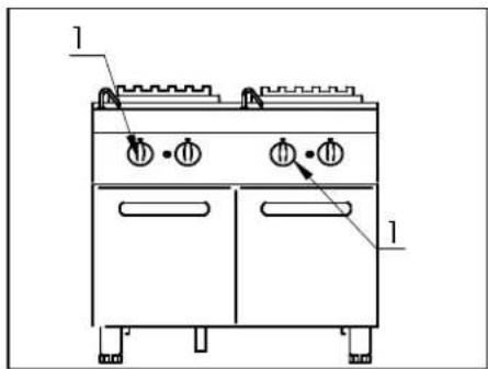
Fig. - Abb. 18: Scarico vasca\ Vidage de la marmite \ Emptying the tub \Entleeren des Beckens

Fig. – Abb. 20: : Sostituzione componenti elettrici di comando\ Remplacement composants électriques de contrôle \ Replacement of electric components\ Ersetzen von elektrischen Komponenten
(Tableau 1) CARACTÉRISTIQUES TECHNIQUES (FR-BE-LU)
| Modèle Description | Dimensions LxPxH [mm] | Puiss. gaz (B) [Kw] | Type (A) | Consommation GPL (G30) (D) [Kg/h] | Consommation METHANE (G20) (C) [m3/h] | Air de comb.. [m3/h] | Racc. gaz | Puiss. élect. (E) [Kw] | Tension (F) [V] | Fréq. (G) [Hz] | Câble type H07 RN-F [mm2] | Press. alimen. Eau MAX [kPa] | Raccord eau | |
| 2853051 | Marmite à gaz 1⁄2 module 400x700x845 8,7 A1 | 0,6860 0,9206 17,4 | UNI-ISO 7/1 R 1⁄2 | -- | - 300 UNI-ISO 7/1 R 1⁄2 | |||||||||
| 2853061 | Marmite à gaz 3⁄4 module | 600x700x845 | 13,9 | A1 | 1,0961 | 1,470 | 27,8 | UNI-ISO 7/1 R 1⁄2 | -- | - 300 UNI-ISO 7/1 R 1⁄2 | ||||
| 2853101 | Marmite à gaz 1 module | 800x700x845 | 17,4 | A1 | 1,3721 | 1,841 | 34,8 | UNI-ISO 7/1 R 1⁄2 | -- | - 300 UNI-ISO 7/1 R 1⁄2 | ||||
| 286305 | Marmite électrique 1⁄2 module | 400x700x845 | - | - | - | - | - | - | 7 | 230 3 – 400 3N | 50 4 x 2,5 – 5 x 1.5 | 300 UNI-ISO 7/1 R 1⁄2 | ||
| 286310 | Marmite électrique 1 module | 800x700x845 | - | - | - | - | - | - | 14 | 230 3 – 400 3N | 50 | 4 x 6 – 5 x 2,5 | 300 UNI-ISO 7/1 R 1⁄2 | |
(Tableau 2) CARACTÉRISTIQUES BRÛLEURS (LU - CAT. I _2E )


2853051
(G=Gas;
C= Carico acqua \ Remplissage d'eau \ Water filling \ Water vullen;
S= Scarico acqua \ Évacuer l'eau \ Water emptying \ Waterafvoer)

2853061
(G=Gas;
C= Carico acqua \ Remplissage d'eau \ Water filling Water vullen;
S= Scarico acqua \ Évacuer l'eau \ Water emptying \ Waterafvoer)


2853101
(G=Gas;
C= Carico acqua \ Remplissage d'eau \ Water filling \ Water vullen;
S= Scarico acqua \ Évacuer l'eau \ Water emptying \ Waterafvoer)
286305
(E= elettrico \ électrique \ electric\ Elektrisch
C= Carico acqua \ Remplissage d'eau \ Water filling \ Water vullen;
S= Scarico acqua \ Évacuer l'eau \ Water emptying \ Waterafvoer)

natural_image
Technical drawing of two rectangular electronic components with grid patterns, dimensioned in millimeters (700 and 800), no readable text or symbols.
286310
(E= elettrico \ électrique \ electric\Elektrisch
C= Carico acqua \ Remplissage d'eau \ Water filling \ Water vullen;
S= Scarico acqua \ Évacuer l'eau \ Water emptying \ Waterafvoer)
natural_image
Mechanical assembly diagram showing a linkage mechanism with no visible text or symbols
Figg.. – Afb. 10 : Sostituzione ugello bruciatore - Regolazione dell'aria primaria \ Changement du gicleur du brûleur - Réglage de l'air primaire \ Substituting the bûrner nozzle - Regulating the primary air \ Vervanging van de sproeier van de hoofdgasbrander - Primärluftregelung des Hauptbrenners

natural_image
Technical line drawing of a mechanical device with multiple ports and mounting brackets (no text or symbols)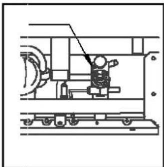
natural_image
Technical line drawing of a mechanical assembly with no visible text or symbolsFigg.. – Afb. 11, 12: Sostituzione del By-Pass \ Changement du by-pass \ Substituting the By-Pass Vervanging van de bypass

natural_image
Line drawing of a simple kitchen appliance with front panels and side legs (no text or symbols)
natural_image
Line drawing of a two-door electric stove with front-mounted fans and side doors (no text or symbols)natural_image
Mechanical assembly diagram showing a lever mechanism with rotating components (no text or labels)
natural_image
Line drawing of a two-door electric stove with front-mounted fans and side-mounted doors (no text or symbols)Fig. – Afb. 18: Scarico vasca\ Vidage de la marmite \ Emptying the tub \Legen van de bak
Fig. – Afb. 19: Resistenze \ Résistances \ Elements\ Verwarmingselementen

natural_image
Technical line drawing of a mechanical assembly with no visible text or symbols
natural_image
Technical line drawing of a mechanical assembly with no visible text or symbolsFig. – Afb. 20: : Sostituzione componenti elettrici di comando\ Remplacement composants électriques de contrôle \ Replacement of electric components\ Vervanging van elektrische componenten


2853051
(G=Gaz;
C= Carico acqua \ Remplissage d'eau \ Water filling \ Napelnianie woda; S=
Scarico acqua \ Évacuer l'eau \ Water emptying \ Opróżnianie z wody)

2853061
(G=Gaz;
C= Carico acqua \ Remplissage d'eau \ Water filling \ Napelnianie woda; S=
Scarico acqua \ Évacuer l'eau \ Water emptying \ Opróżnianie z wody)

2853101
(G=Gaz;
C= Carico acqua \ Remplissage d'eau \ Water filling \ Napelnianie woda; S=
Scarico acqua \ Évacuer l'eau \ Water emptying \ Opróżnianie z wody)


286305
(E= elettrico \électrique \electric\ Elektryczne
C= Carico acqua \ Remplissage d'eau \ Water filling \ Napelnianie woda; S=
Scarico acqua \ Évacuer l'eau \ Water emptying \ Opróżnianie z wody)

natural_image
Technical drawing of two rectangular electronic components with grid patterns, dimensioned in millimeters (700 and 800), no readable text or symbols.
286310
(E= elettrico \ électrique \ electric\ elektryczne
C= Carico acqua \ Remplissage d'eau \ Water filling \ Napelnianie woda; S=
Scarico acqua \ Évacuer l'eau \ Water emptying \ Opróżnianie z wody)
natural_image
Mechanical assembly diagram showing a motor and linkage mechanism (no text or labels)
Figg.. - Rys. 10 : Sostituzione ugello bruciatore - Regolazione dell'aria primaria \ Changement du gicleur du brûleur - Réglage de l'air primaire Substituting the burner nozzle - Regulating the primary air \ Wymiana dyszy palnika głównego - Primärluftregelung des Hauptbrenners

natural_image
Technical line drawing of a mechanical device with multiple ports and mounting brackets (no text or symbols)
natural_image
Technical line drawing of a mechanical assembly with no visible text or symbolsFigg. – Rys. 11, 12: Sostituzione del By-Pass \ Changement du by-pass \ Substituting the By-Pass \ Wymiana By-Pass'u

natural_image
Line drawing of a simple kitchen appliance with front panels and side legs (no text or symbols)
natural_image
Line drawing of a two-door electric stove with front-mounted fans and side doors (no text or symbols)natural_image
Mechanical assembly diagram showing pipe connection and rotational motion (no text or symbols)
natural_image
Line drawing of a two-door electric stove with front-mounted fans and side-mounted doors (no text or symbols)Fig. – Rys. 18: Scarico vasca\ Vidage de la marmite \ Emptying the tub \ Opróźnianie zbiornika
Fig. – Rys. 19: Resistenze \ Résistances \ Elements\ Grzałki

natural_image
Technical line drawing of a mechanical assembly with no visible text or symbols
natural_image
Technical line drawing of a mechanical device with no visible text or symbolsFig. – Rys. 20: : Sostituzione componenti elettrici di comando\ Remplacement composants électriques de contrôle \ Replacement of electric components\ Wyniana elektrycznych elementów składowych

- WARNINGS
- General
- For the installer
- TECHNICAL FEATURES
- Declaration of compliance
- DESCRIPTION OF APPLIANCES
- Gas Appliances
- Electric Appliance
- PROVISIONS FOR INSTALLATION
- Installation
- Fumes evacuation
- Preliminary operations
- Gas Connection
- Electric connection
- Connection to the water mains
- Drainage connection
- Checking gas tightness and pressure (fig. 9 - pag. 5).
- Checking the power
- Checking pilot burner
- Checking regulation of primary air
- REGULATIONS AND SUBSTITUTION FOR USING DIFFERENT GAS THAN THE TYPE PROVIDED FOR
- Functioning with different gas than the type provided for
- Substituting the burner nozzle (fig.10 - pag. 5)
- Substituting the By-Pass (fig. 11, 12 - pag. 5)
- INSTRUCTIONS FOR USE
- Electric pasta cooker (fig. 16 - pag. 6)
- Emptying the tub (fig. 18 - pag. 6)
- Abnormal functioning
- CARE AND MAINTENANCE OF THE APPLIANCE
- Cleaning
- Maintenance
- SUBSTITUTING COMPONENTS
- Safety cock
- Thermocouple
- Elements (fig. 19 pag. 8)
- Electric components of the electric pasta cooker (fig. 20, pag. 8)
- WHEN SUBSTITUTING, ONLY ORIGINAL SPARE PARTS SUPPLIED BY THE MANUFACTURER MUST BE USED. THE OPERATION MUST BE CARRIED OUT BY AUTHORIZED PERSONNEL.
- THE MANUFACTURER RESERVES THE RIGHT TO WITHOUT NOTICE MODIFY THE FEATURES OF THE APPLIANCES DESCRIBED IN THIS MANUAL.
- MARMITES A GAZ MARMITES ÉLECTRIQUES SÉRIE 70
Brand : BARTSCHER
Model : 286310
Category : Pasta machine