
HSBC 300 L cool - Heat pump STIEBEL ELTRON - Free user manual and instructions
Find the device manual for free HSBC 300 L cool STIEBEL ELTRON in PDF.
| Product type | Boiler (heat pump connected with buffer tank and DHW) |
| Brand | Stiebel Eltron |
| Model | HSBC 300 L cool |
| DHW tank capacity | 270 L (nominal capacity) |
| Buffer tank capacity | 100 L |
| Dimensions (H x W x D) | 1918 x 680 x 910 mm |
| Weight empty / full | 248 kg / 639 kg |
| Power supply | 230 V ~ 50 Hz |
| Energy efficiency class | B |
| Standing losses | 61 W |
| Max. permissible pressure DHW tank | 1.0 MPa (10 bar) |
| Max. permissible pressure buffer tank | 0.3 MPa (3 bar) |
| Max. permissible temperature | 85 °C (DHW tank) |
| Max. flow rate | 25 L/min |
| Main functions | Heating, cooling (7 °C / 12 °C) of rooms, domestic hot water production |
| Protection rating | IP20 |
| Included accessories | 4 adjustable feet |
| Cleaning | Damp cloth, no abrasive or corrosive products |
| Safety | All-pole disconnection device (min. 3 mm opening), frost protection |
| Maintenance | Regular check of electrical components and safety group by an installer |
| Spare parts / Accessories | Additional heating element HSBC 3-HE, hydraulic kit HSBC 3-HKM, tube kit RBS-SBC, sacrificial anode |
Frequently Asked Questions - HSBC 300 L cool STIEBEL ELTRON
User questions about HSBC 300 L cool STIEBEL ELTRON
0 question about this device. Answer the ones you know or ask your own.
Ask a new question about this device
Download the instructions for your Heat pump in PDF format for free! Find your manual HSBC 300 L cool - STIEBEL ELTRON and take your electronic device back in hand. On this page are published all the documents necessary for the use of your device. HSBC 300 L cool by STIEBEL ELTRON.
USER MANUAL HSBC 300 L cool STIEBEL ELTRON
BEDIENUNG UND INSTALLATION OPERATION AND INSTALLATION UTILISATION ET INSTALLATION BEDIENING EN INSTALLATIE USO E INSTALLAZIONE
Integralspeicher | Integral cylinder | Ballon combiné | Combiboiler | Caldaia integrale
» HSBC 300 cool
» HSBC 300 L cool

natural_image
Line drawing of a rectangular electronic device with two cylindrical components on top and a side panel (no text or symbols)STIEBEL ELTRON
BESONDERE HINWEISE
BEDIENUNG
- WPL 10 AC
- WPL 15/20/25 AC(S)
- WPL 19/24 I
HSBC 300 L cool:
- WPL 09/17 ICS/IKCS classic
- WPL 19/24 IK
- WPF 04/05/07/10 (cool)
natural_image
Diagram showing a mechanical setup with a rotating component and a spherical component, no text or symbols present.natural_image
Technical line drawing of a rectangular electronic device with a black arrow indicating a directional flow (no text or symbols present)text_image
Exploded view diagram of an electronic device showing internal components and labeled partsD0000080535
1 Dämmelement 1
2 Dämmelement 2
3 Dämmstoffschraube
4 Dämmelement 3
text_image
Technical diagram of an industrial equipment cabinet with labeled components and a magnified inset showing a device's view.
Hinweis
text_image
Technical diagram showing a computer tower with labeled components and a magnified view of the internal component being inserted.natural_image
Technical diagram showing a mechanical assembly with an inset close-up of a component, no visible text or symbols.natural_image
Technical line drawing of a mechanical or electrical component with pipes and housing (no text or symbols)natural_image
Cross-sectional diagram of a mechanical assembly with internal components and directional arrows (no text or labels)natural_image
Technical line drawing of a mechanical assembly with pipes and housing (no text or symbols)natural_image
Technical line drawing of an internal electronic device with visible ports and wiring (no text or symbols)natural_image
Technical line drawing of an industrial machine or control unit with multiple ports and mounting brackets (no text or symbols visible)natural_image
Diagram of a mechanical assembly with a box and a component, showing an arrow indicating direction (no text or symbols present)natural_image
Technical line drawing of an electrical enclosure with internal components and wiring (no text or symbols)natural_image
Technical line drawing of a U-shaped mechanical component with a labeled section (no text or symbols beyond label)DEUTSCH
natural_image
Technical diagram of a mechanical component with an arrow indicating direction (no text or symbols present)text_image
Technical diagram illustrating mechanical assembly steps with labeled components and a 1-2 Nm scale indicator.flowchart
graph TD
    subgraph XD03.2_XD03.3
        A["MKP (X2.4)"] --> B["5"]
        A --> C["6"]
        A --> D["7"]
        A --> E["8"]
        A --> F["9"]
        G["MISCHER (X2.14)"] --> H["LA 1"]
        G --> I["LZ 2"]
        G --> J["N 3"]
        G --> K["4"]
    end
    subgraph XD04
        L["BAK"] --> M["MA11"]
        N["BU"] --> M
        O["GNYE"] --> M
        P["BN"] --> Q["MA19"]
        R["BU"] --> Q
        S["BN"] --> Q
    end
    T["BT13"] --> U["T (MK) (X1.6)"]
    U --> V["9"]
    U --> W["10"]
    X["D0000081761"]
natural_image
Technical mechanical assembly diagram showing internal components and shafts (no text or labels)text_image
1 2 D00000805A-1natural_image
Technical line drawing of an electrical enclosure with coiled wires and components (no text or symbols)text_image
Technical diagram of a refrigerant or industrial device with labeled components 1 and 2D0000080429
natural_image
Technical line drawing of a mechanical assembly with an inset close-up showing internal components (no text or symbols)text_image
Technical diagram of an electrical enclosure with labeled components and wiring connectionsnatural_image
Technical line drawing of an electronic device showing internal components and mounting brackets (no text or symbols)text_image
XD08 XD00 XF 17 XDO4 T(MK) DXLB T(KUE) DXLB T(WW) DXLB T(Puffer) DXL4 PWM DXLB =+ = + = + - 2 1 D0000080433natural_image
Technical diagram showing a mechanical assembly with a magnified inset of a component being inserted (no text or symbols present)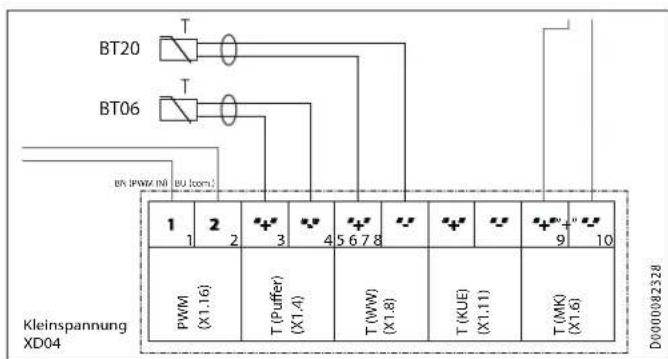
text_image
BT20 BT06 BK (PWM IN) BU Iom. 1 2 3 4 5 6 7 8 9 10 PWM (X1.16) T (Puffer) (X1.4) T (WW) (X1.8) T (KUE) (X1.11) T (MK) (X1.6) D0000082328 Kleinspannung XD04Betroffene Geräte:
- 238826
- 232909 - 232912
- 232915 - 232918
HSBC 300 L cool
WPF 04 - WPF 10
WPF 04 cool - WPF 10 cool
natural_image
Technical diagram showing a mechanical assembly with an inset close-up of a lever mechanism (no text or symbols present)natural_image
Technical line drawing of a mechanical or electrical component with pipes and housing (no text or symbols)natural_image
Technical line drawing of a mechanical assembly with an inset close-up showing internal components (no text or symbols)natural_image
Technical line drawing of a dual air conditioning unit with fan and cooling unit (no text or symbols)D0000080569
HSBC 300 L cool

natural_image
Technical line drawing of a dual-chamber industrial system with pipes and control panels (no text or symbols)D0000080571D0000080570

natural_image
Pure technical line drawing of two vertical rectangular units connected by pipes, no text or symbols present- General information 37
1.1 Relevant documents 37
1.2 Safety instructions 37
1.3 Other symbols in this documentation 37
1.4 Information on the appliance 37
1.5 Units of measurement 37 - Safety 38
2.1 Intended use 38
2.2 General safety instructions 38
2.3 Test symbols 38 - Appliance compatibility 38
- Appliance description 38
- Cleaning, care and maintenance 39
- Troubleshooting 39
INSTALLATION
- Safety 40
7.1 General safety instructions 40
7.2 Instructions, standards and regulations 40 - Appliance description 40
8.1 Standard delivery 40
8.2 Accessories 40 - Preparation 40
9.1 Installation site 40
9.2 Transport and handling 41 - Installation 46
10.1 Positioning the appliance 46
10.2 Heating water connection and safety valve ____ 46
10.3 DHW connection and safety assembly 52
10.4 Filling the system 53
10.5 Venting the appliance 54 - Electrical connection 54
11.1 Control voltage 55
11.2 Safety extra low voltage 56
11.3 Power supply for auxiliary heating element 56
11.4 Sensor installation 56 - Commissioning 58
12.1 Wilo-Para .../Sc circulation pumps 58
12.2 Appliance handover 59 - Appliance shutdown 59
- Maintenance 59
- Specification 60
15.1 Dimensions and connections 60
15.2 Wiring diagram 62
15.3 Hydraulic diagrams 64
15.4 Energy consumption data 65
15.5 Data table 65
15.6 Accessories 66
GUARANTEE
ENVIRONMENT AND RECYCLING
SPECIAL INFORMATION
- The appliance may be used by children over 8 years of age and persons with reduced physical, sensory or mental capabilities or a lack of experience and expertise, provided that they are supervised or they have been instructed on how to use the appliance safely and have understood the potential risks. Children must never play with the appliance. Children must never clean the appliance or perform user maintenance unless they are supervised.
- The connection to the power supply must be in the form of a permanent connection. Ensure the appliance can be separated from the power supply by an isolator that disconnects all poles with at least 3 mm contact separation.
- Observe all applicable national and regional regulations and instructions.
- Observe minimum distances (see chapter "Installation / Preparations / Installation site").
- Only a qualified contractor should carry out installation, commissioning, maintenance and repair of the appliance.
DHW cylinders
- Drain the appliance as described in chapter "Installation / Maintenance / Draining the DHW cylinder".
- Observe the maximum permissible pressure (see chapter "Installation / Specification / Data table").
OPERATION
1. General information
The chapters "Special information" and "Operation" are intended for both users and qualified contractors.
The chapter "Installation" is intended for qualified contractors.

Note
Read these instructions carefully before using the appliance and retain them for future reference.
Pass on the instructions to a new user if required.
1.1 Relevant documents
Operating and installation instructions for the connected heat pump
Operating and installation instructions for all other system components
1.2 Safety instructions
1.2.1 Structure of safety instructions

KEYWORD Type of risk
Here, possible consequences are listed that may result from failure to observe the safety instructions.
▶ Steps to prevent the risk are listed.
1.2.2 Symbols, type of risk
Symbol Type of risk

Injury

Electrocution

Burns
(burns, scalding)
1.2.3 Keywords
| KEYWORD | Meaning |
| DANGER | Failure to observe this information will result in serious injury or death. |
| WARNING | Failure to observe this information may result in serious injury or death. |
| CAUTION | Failure to observe this information may result in non-serious or minor injury. |
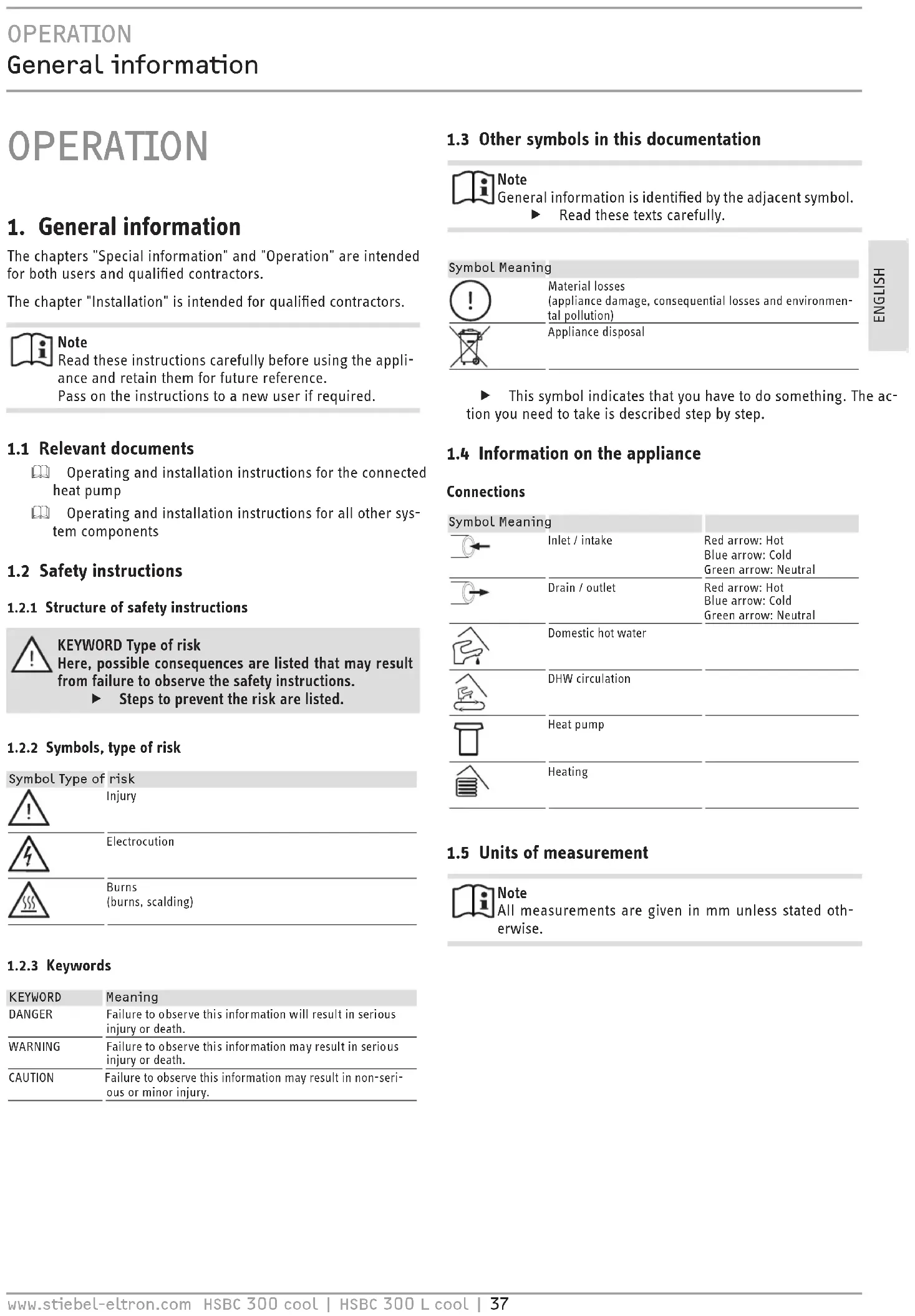
1.3 Other symbols in this documentation

Note
General information is identified by the adjacent symbol.
▶ Read these texts carefully.
Symbol Meaning

Material losses
(appliance damage, consequential losses and environmental pollution)
Appliance disposal

This symbol indicates that you have to do something. The action you need to take is described step by step.
1.4 Information on the appliance
Connections
| Symbol Meaning | ||
 | Inlet / intake | Red arrow: HotBlue arrow: ColdGreen arrow: Neutral |
 | Drain / outlet | Red arrow: HotBlue arrow: ColdGreen arrow: Neutral |
 | Domestic hot water | |
 | DHW circulation | |
 | Heat pump | |
 | Heating | |
1.5 Units of measurement

Note
All measurements are given in mm unless stated otherwise.
2. Safety
2.1 Intended use
This appliance is intended to be used for seasonal heating and cooling of interiors (7 °C / 12 °C) and for DHW heating.
The appliance is intended for domestic use. It can be used safely by untrained persons. The appliance can also be used in non-domestic environments, e.g. in small businesses, as long as it is used in the same way.
Any other use beyond that described shall be deemed inappropriate. Observation of these instructions and of the instructions for any accessories used is also part of the correct use of this appliance.
2.2 General safety instructions

WARNING Burns
There is a risk of scalding at outlet temperatures in excess of 43^ C.

WARNING Injury
The appliance may be used by children over 8 years of age and persons with reduced physical, sensory or mental capabilities or a lack of experience and expertise, provided that they are supervised or they have been instructed on how to use the appliance safely and have understood the potential risks. Children must never play with the appliance. Children must never clean the appliance or perform user maintenance unless they are supervised.

WARNING Injury
For safety reasons, only operate the appliance with the front casing closed.

Note
The DHW cylinder is under supply pressure. During the heat-up process, expansion water will drip from the safety valve.
▶ If water continues to drip when heating is completed, please inform your qualified contractor.

Material losses
The system's active frost protection is not guaranteed if the power supply is interrupted.
▶ Never interrupt the power supply even outside the heating season.
2.3 Test symbols
See type plate on the appliance.
3. Appliance compatibility
The appliance can be operated in conjunction with the following air | water heat pumps:
HSBC 300 cool:
- WPL 10 AC
- WPL 15/20/25 AC(S)
- WPL 19/24 I
HSBC 300 L cool:
- WPL 09/17 ICS/IKCS classic
- WPL 19/24 IK
- WPF 04/05/07/10 (cool)
4. Appliance description
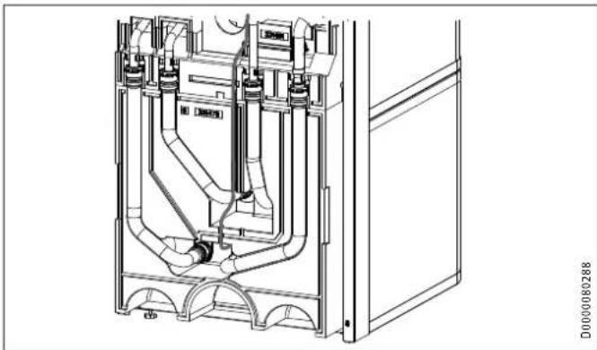
The buffer cylinder and DHW cylinder with indirect coil are arranged one above the other and can be separated for easier handling.
The appliance has a plastic jacket with foam insulation and is equipped with a removable front casing. The appliance is connected hydraulically and electrically to the heat pump. All hydraulic connections are made at the top (heating) and rear (DHW).
In addition to the DHW cylinder and the buffer cylinder, further system components are integrated:
- Highly efficient circulation pump for a heating circuit without mixer
- 3/2-way diverter valve
- Cylinder charging pump (only in HSBC 300 cool)
DHW cylinders
The steel cylinder is coated on the inside with special direct enamel and is equipped with a signal anode. The anode with consumption indicator protects the cylinder interior from corrosion.
The heating water heated by the heat pump is pumped through an indirect coil inside the DHW cylinder. The heat channelled through the indirect coil is thus transferred to the domestic hot water.
Buffer cylinder
The steel cylinder provides hydraulic separation between the flow rates of heat pump and heating circuit. The heating water heated by the heat pump is transferred to the buffer cylinder by the cylinder charging pump (only in HSBC 300 cool). When a demand is issued, the integral heating circuit pump delivers the heating water to the heating circuit.
5. Cleaning, care and maintenance
▶ Have the electrical safety of the appliance and the function of the safety assembly regularly checked by a qualified contractor.
▶ Never use abrasive or corrosive cleaning agents. A damp cloth is sufficient for cleaning the appliance.
Signal anode with consumption indicator

Material losses
If the consumption indicator changes colour from white to red, have the signal anode checked by a qualified contractor and if necessary replaced.
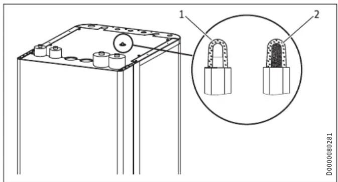
text_image
1 2 D00000802811 White = Anode OK
2 Red = Requires checking by qualified contractor
Scaling
Almost every type of water will deposit limescale at high temperatures. This settles inside the appliance and affects both performance and service life. A qualified contractor who knows the local water quality will tell you when the next service is due.
▶ Check the taps regularly. Limescale deposits at the tap outlets can be removed using commercially available descaling agents.
▶ Regularly activate the safety valve to prevent it from becoming blocked, e.g. by limescale deposits.
6. Troubleshooting
| Problem Cause Remedy | ||
| The water does not heat up. The heating does not work. | There is no power. | Check the fuses/MCBs in your fuse box/distribution board. |
If you cannot remedy the fault, contact your qualified contractor. To facilitate and speed up your enquiry, please provide the serial number from the type plate (000000-0000-000000).
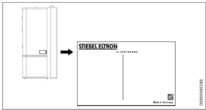
text_image
STIEBEL ELTRON File: (1) 《通用》第3章通用 Made in Germany D000080280INSTALLATION
7. Safety
Only a qualified contractor should carry out installation, commissioning, maintenance and repair of the appliance.
7.1 General safety instructions
We guarantee trouble-free function and operational reliability only if original accessories and spare parts intended for the appliance are used.
7.2 Instructions, standards and regulations

Note
Observe all applicable national and regional regulations and instructions.
8. Appliance description
8.1 Standard delivery
The following are delivered with the appliance:
- 4 adjustable feet
Only HSBC 300 L cool:
- 2 copper adaptors
(28/28/28 mm, for joining flow and return)
- 4 copper reducers (28/22 mm)
8.2 Accessories
8.2.1 Required accessories
Safety assemblies and pressure reducing valves are available to suit the prevailing supply pressure. These type-tested safety assemblies protect the appliance against impermissible excess pressure.
8.2.2 Additional accessories
- Pump assembly for a heating circuit with mixer HSBC 3-HKM
- Pipe assembly RBS-SBC
- Auxiliary heating element HSBC 3-HE
- Pressure hoses
- Water softening fitting HZEA
- Temperature sensor for cooling
Pipe assembly RBS-SBC
The hydraulic connections can be routed upwards at the rear of the DHW cylinder using the RBS-SBC pipe assembly available as an accessory.
9. Preparation
9.1 Installation site

Material losses
Never install the appliance in wet rooms.
Install the appliance near the draw-off point in a dry room free from the risk of frost. To reduce line losses, keep the distance short between the appliance and the heat pump.
Ensure the floor has sufficient load bearing capacity and evenness (for weight, see chapter "Specification / Data table").
The room must not be subject to a risk of explosions arising from dust, gases or vapours.
If you are installing the appliance in a boiler room together with other heating equipment, ensure that the operation of the other heating equipment will not be impaired.
Minimum clearances
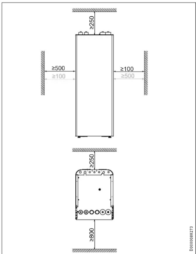
text_image
≥250 ≥500 ≥100 ≥100 ≥500 ≥250 ≥800 D0000080273The minimum side clearances can be swapped between left and right.
9.2 Transport and handling

Material losses
Store and transport the appliance at temperatures between -20 °C and +60 °C.
Handling
▶ Undo the 4 screws from the non-returnable pallet.
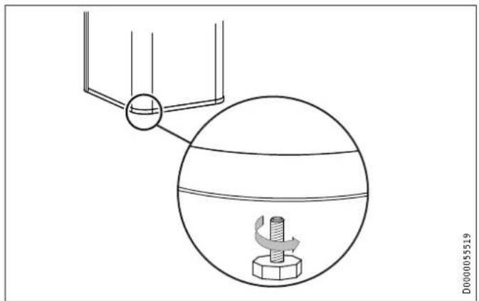
natural_image
Diagram showing a mechanical setup with a rotating component and a spherical component, no text or symbols present.▶ Tilt the appliance and screw the 4 adjustable feet into the appliance.
▶ Lift the appliance off the pallet.
If narrow doors or hallways hinder handling, you can separate the upper and lower sections of the appliance as described in the following chapters.
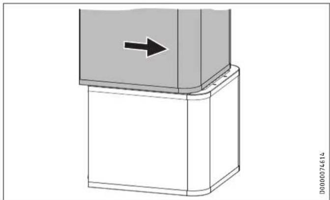
9.2.1 Removing / fitting the front casing
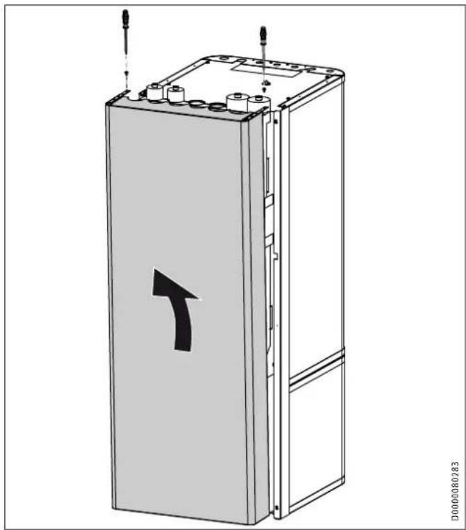
natural_image
Technical line drawing of a rectangular electronic device with a black arrow indicating forward direction (no text or symbols present)Remove the 2 locking screws on the top of the front casing.
▶ Unhook the front casing towards the top.
▶ Remove the earth cable from the front casing.
▶ Fit the front casing in reverse order.
9.2.2 Overview of insulation segments
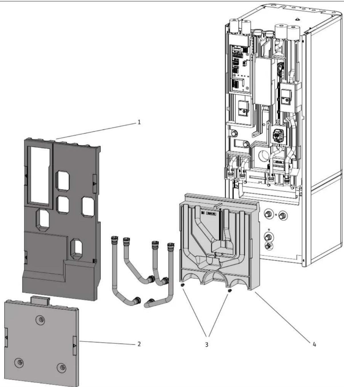
text_image
Exploded view diagram of an electronic device showing internal components and labeled partsD0000080535
1 Insulation segment 1
2 Insulation segment 2
3 Insulation material screw
4 Insulation segment 3
9.2.3 Separating / joining the appliance sections
Separating the appliance sections

Material losses
Unscrewing the fastening screws destroys the threads in the insulation segment.
▶ To open the 3 fixing tabs, loosen the fastening screws slightly but do not unscrew them completely.
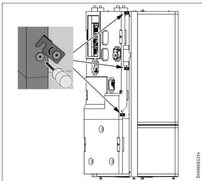
text_image
Technical diagram of an industrial control room with labeled components and a magnified inset showing mechanical assembly details.
Note
To make removal simpler, the insulation segments have labelled recessed grips on the left and right.
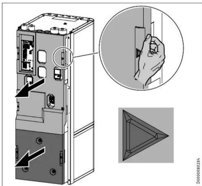
text_image
Technical diagram showing a device rear panel with labeled ports and a magnified view of the internal component being inserted.▶ Remove insulation segment 1.
▶ Remove insulation segment 2.

natural_image
Technical diagram showing a mechanical assembly with an inset close-up of a component, no visible text or symbols.▶ Pull the "heating sensor" out of the buffer cylinder.
natural_image
Technical line drawing of a mechanical or electrical component with pipes and connections (no text or symbols)▶ Release the sensor lead from the guide groove.
natural_image
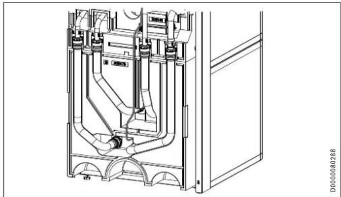
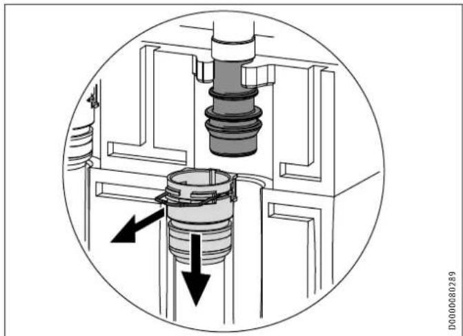
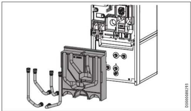
Cross-sectional diagram of a mechanical assembly with internal components and directional arrows (no text or labels)▶ Disconnect the push-fit connectors of the 4 hydraulic connections. To do this, pull the spring clips fully out with a screwdriver.
▶ Pull the hydraulic connectors as indicated.
natural_image
Technical line drawing of a mechanical assembly with pipes and housing (no text or symbols)▶ Remove the 4 hydraulic hoses.
▶ Remove the 2 insulation material screws.
▶ Remove insulation segment 3.
natural_image
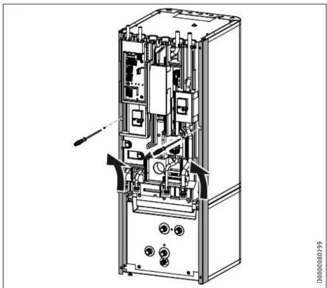
Technical line drawing of an internal electronic device with visible ports, connectors, and a screwdriver (no text or symbols)▶ Undo the 2 locking screws on the side profile strips.
▶ Lift up and unhook the side profile strips.
natural_image
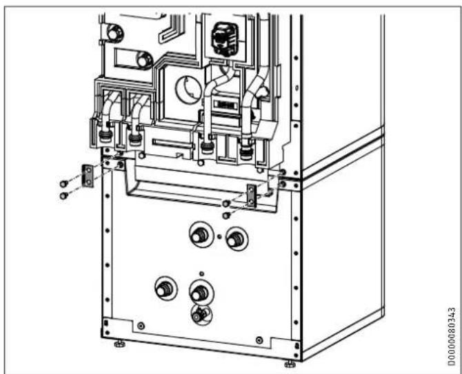
Technical line drawing of an industrial machine or control unit with multiple ports and mounting brackets (no text or symbols visible)▶ Release the 4 screws on the tabs at the front of the appliance.
natural_image
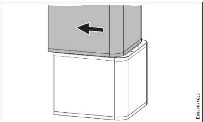
Diagram of a mechanical component with a left-pointing arrow, no text or symbols present▶ Pull the upper section of the appliance towards the front.
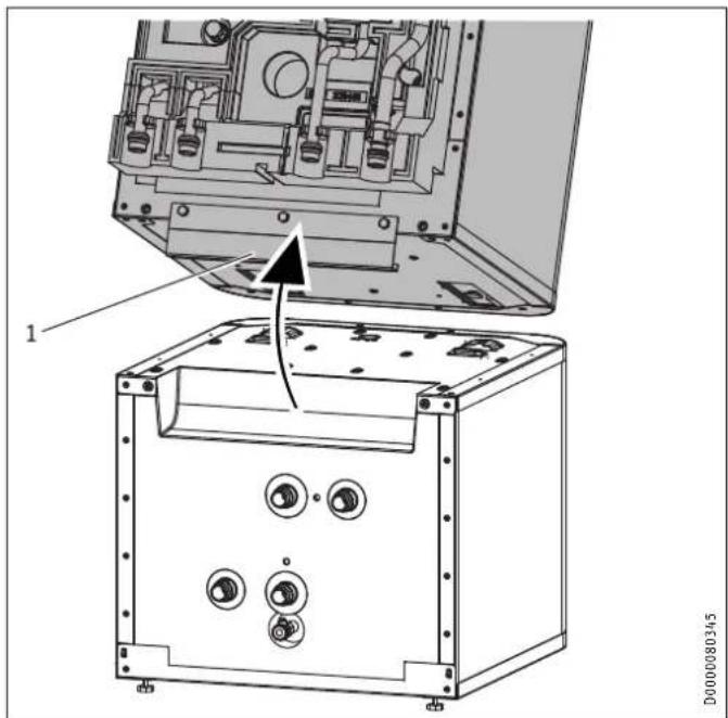
text_image
1 D00000803451 Handle
▶ Tip the upper section of the appliance backwards. Use the handle for improved grip.
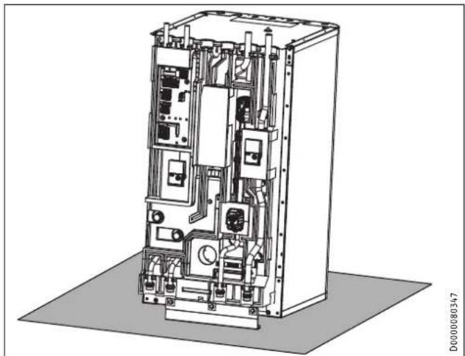
natural_image
Technical line drawing of an electrical enclosure with internal components and wiring (no text or symbols)▶ Place the upper section of the appliance on a base to prevent damage.
Joining appliance sections

Material losses
To prevent condensation forming, the insulation segments must fit closely against the lower section with no gaps.
▶ When inserting the insulation segments, ensure that the joint grooves are kept clear
▶ Tap the insulation segments down with your hand.
Rejoin the appliance sections in reverse order.
The positioning aids and the dotted line marking provide assistance when positioning and inserting the upper appliance section into the guide groove on the lower section:
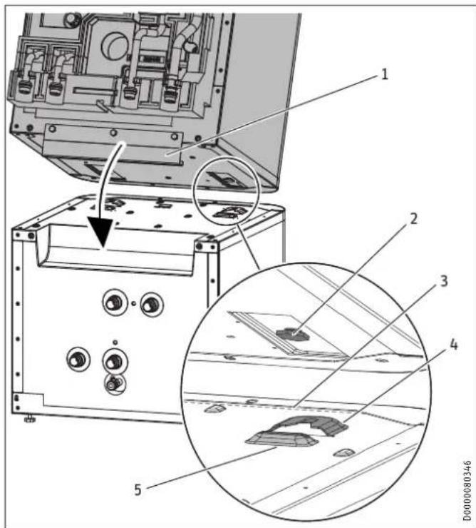
text_image
Technical diagram of an electronic device with labeled components and a magnified inset showing internal structure details.1 Handle
2 Guide pin
3 Dotted line (perforation in the panel)
4 Guide groove
5 Positioning aid
natural_image
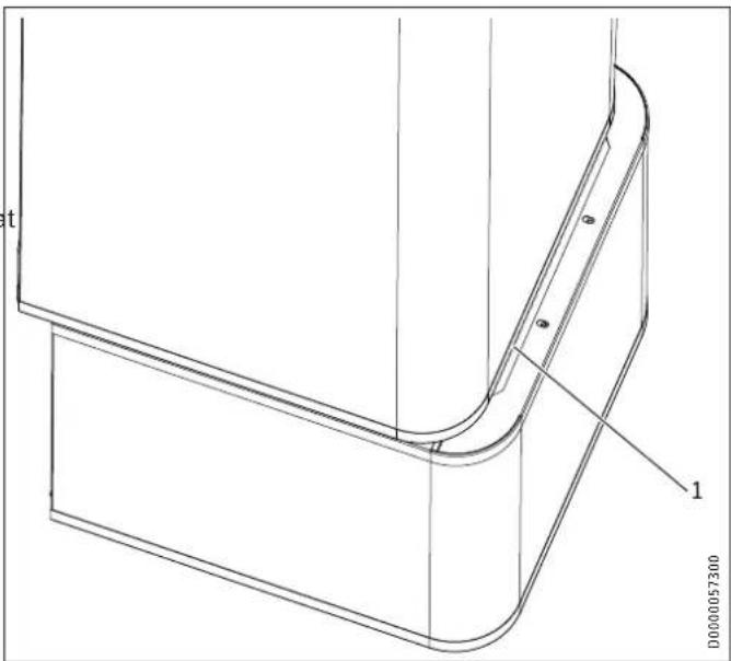
Technical line drawing of a U-shaped mechanical component with labeled parts (no text or symbols beyond labels)1 Dotted line (perforation in the panel)
▶ Place the upper appliance section onto the lower appliance section along the dotted line.
natural_image
3D diagram of a mechanical component with an arrow indicating direction, no text or symbols present▶ Slide the upper appliance section to the back until it is flush with the lower appliance section. If the appliance sections are joined correctly, the final position is determined by the guide groove and guide pin.
▶ Secure the tabs on the appliance front.
▶ Fit the side profile strips.
▶ Fit insulation segment 3 and the 4 hydraulic hoses.
▶ Connect the push-fit connectors of the 4 hydraulic connections. Ensure that the spring clips click into place.
▶ Insert the "heating sensor" into the buffer cylinder.
▶ Lay the sensor lead in the guide groove provided for this purpose.
▶ Fit insulation segment 2.
▶ Fit insulation segment 1.
▶ Fit the front casing.
10. Installation
10.1 Positioning the appliance
▶ When positioning the appliance, observe minimum clearances (see chapter "Preparations / Installation site").
▶ Use the adjustable feet to compensate for any unevenness in the floor.
10.2 Heating water connection and safety valve
10.2.1 Safety instructions

Material losses
The heating system to which the appliance is connected must be installed by a qualified contractor in accordance with the water installation drawings in the technical guides.

Material losses
When fitting additional shut-off valves, install a further safety valve in an accessible location on the heat generator itself or in the flow line in close proximity to the heat generator.
There must be no shut-off valve between the heat generator and the safety valve.
Oxygen diffusion

Material losses
Avoid open vented heating systems and underfloor heating systems with plastic pipes that are permeable to oxygen.
In underfloor heating systems with plastic pipes that are permeable to oxygen and in open vented heating systems, oxygen diffusion may lead to corrosion on the steel components of the heating system (e.g. on the indirect coil of the DHW cylinder, on buffer cylinders, steel radiators or steel pipes).

Material losses
The products of corrosion (e.g. rusty sludge) can settle in the heating system components, which may result in a lower output or fault shutdowns due to reduced cross-sections.
Supply lines
The maximum permissible line length between the appliance and the heat pump will vary, depending on the version of the heating system (pressure drop). As a standard value,
assume a maximum line length of 10 m and a pipe diameter of 22-28 mm.
▶ Insulate the flow and return lines in accordance with regional regulations.
▶ Connect the hydraulic connections with flat gaskets.
Pressure hoses against structure-borne sound transmission:
The appliance and the heat pump are connected to each other hydraulically via pipes carrying heating water. To reduce the transmission of structure-borne sound on the water side, connect the appliance to the heat pump with pressure hoses if these are not already installed in the heat pump.
Pressure differential:
If the available external pressure difference is exceeded, the pressure drop in the heating system could result in a reduced heating output.
▶ When sizing the pipes, ensure that the available external pressure differential is not exceeded (see chapter "Specification / Data table").
▶ When calculating the pressure drop, take account of the flow and return lines and the pressure drop of the heat pump.
The pressure drop must be covered by the available pressure differential.
10.2.2 Fitting the pump assembly (accessory) if required

WARNING Electrocution
Before starting work on the appliance, disconnect all poles from the power supply and drain the heating circuit via the drain valve on the buffer cylinder.
To extend the appliance with a heating circuit with mixer, you can install pump assembly HSBC 3-HKM (available as an accessory).
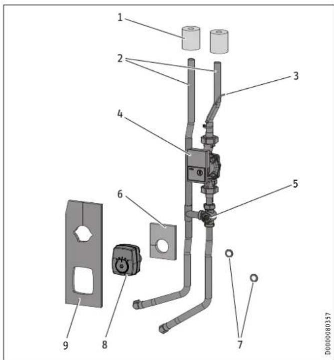
Standard delivery HSBC 3-HKM
text_image
Technical diagram of a mechanical or electrical assembly with numbered components and labeled parts1 Pipe insulation
2 Connection pipes (*)
3 Temperature sensor
4 Heating circuit pump (*)
5 3-way mixer (*)
6 Insulation mat for 3-way mixer
7 Flat gaskets
8 Servomotor for 3-way mixer (*)
9 Insulation mat for 3-way mixer and heating circuit pump
(*) Pipe assembly
Preparation for installation of HSBC 3-HKM
▶ Remove the front casing and insulation segment 1 (see chapter "Installation / Preparations / Transport and handling").
The following components are prefitted on the HSBC side at the pump assembly installation site:
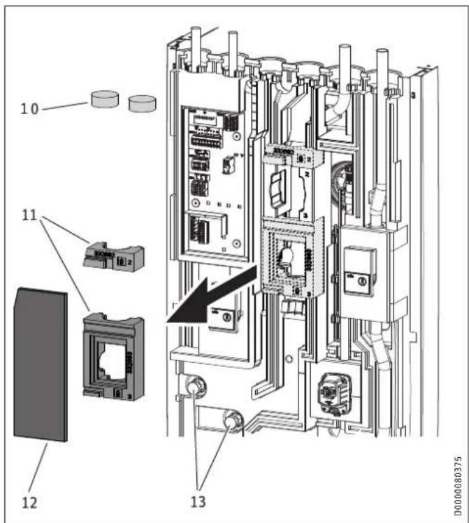
text_image
10 11 12 13 D000008037510 Insulation plugs
11 Profiles for 3-way mixer
12 Insulation mat, closed
13 Adaptor with dummy cap screwed on
▶ Remove the insulation plugs.
▶ Remove the closed insulation mat and profiles for the 3-way mixer and the heating circuit pump.
▶ Counterhold and unscrew the dummy caps from the adaptors.
HSBC 3-HKM installation
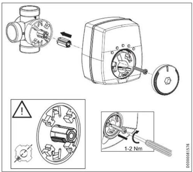
text_image
Technical diagram illustrating mechanical assembly steps with labeled components and safety warning indicators▶ Check the position of the 3-way mixer shaft. Adjust the position if necessary.
text_image
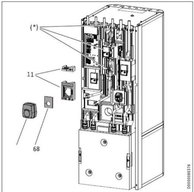
(*) 11 68 D0000080376(*) Pipe assembly inserted
6 Insulation mat for 3-way mixer
8 Servomotor for 3-way mixer
11 Profiles for 3-way mixer
▶ Insert the pipe assembly.
▶ Insert the flat gaskets into the union nuts for the connection pipes.
▶ Counterhold and secure the union nuts to the adaptors.
▶ Check the alignment of the pipes and functional elements of the pump assembly. Retighten all fittings.
▶ Install the profiles for the 3-way mixer over the mixing valve body and above the pump.
▶ Place the insulation mat for the 3-way mixer on the valve body.
▶ Install the servomotor for the 3-way mixer
text_image
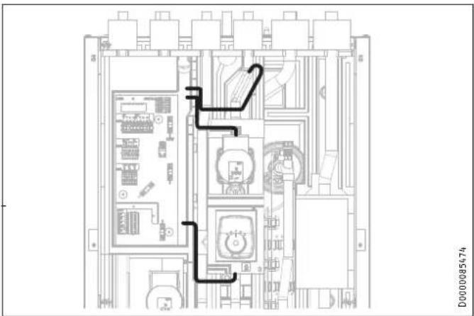
D0000085674Material losses
To prevent condensation from forming, do not lay any cables in the joint grooves of the EPP parts.
▶ Route the pump assembly connecting cable to the control panel as shown.
▶ Slide the pipe insulation over the connection pipe connectors from above.
text_image
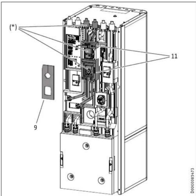
(*) 11 9 D0000085473(*) Pipe assembly inserted
9 Insulation mat for 3-way mixer and heating circuit pump
11 Profiles for 3-way mixer
▶ Insert the insulation mat on the HKM side for the 3-way mixer and the heating circuit pump.
Electrical connection HSBC 3-HKM
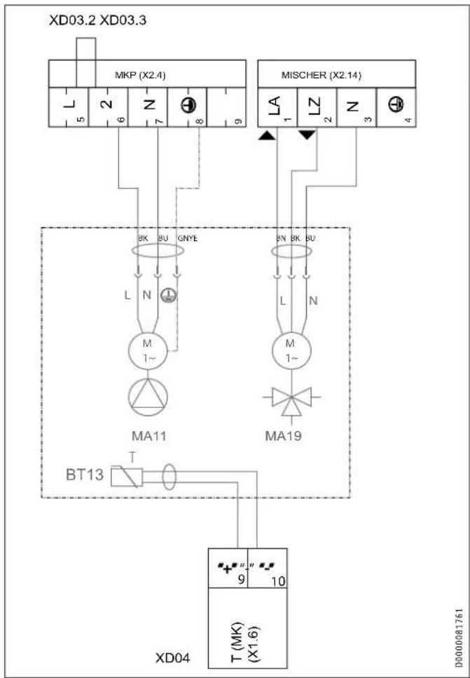
flowchart
graph TD
    subgraph XD03.2_XD03.3
        A["MKP (X2.4)"] --> B["5"]
        A --> C["6"]
        A --> D["7"]
        A --> E["8"]
        A --> F["9"]
        G["MISCHER (X2.14)"] --> H["LA 1"]
        G --> I["LZ 2"]
        G --> J["N 3"]
        G --> K["4"]
    end
    subgraph XD04
        L["BAK"] --> M["BU"]
        N["GNYE"] --> O["1~"]
        P["MA11"] --> Q["T"]
        R["BT13"] --> S["1"]
    end
    subgraph XD04
        T["MA19"] --> U["1~"]
        V["XD04"] --> W["T (MK) (X1.6)"]
    end
    X["9"] --> Y["10"]
    style XD04 fill:#f9f,stroke:#333
    style X fill:#ccf,stroke:#333
▶ Wire up the heating circuit pump and 3-way mixer (see chapter "Installation / Electrical connection / Control voltage").
10.2.3 If necessary, install an HSBC 3-HE auxiliary heating element as an accessory

WARNING Electrocution
Before starting work on the appliance, disconnect all poles from the power supply and drain the DHW cylinder.
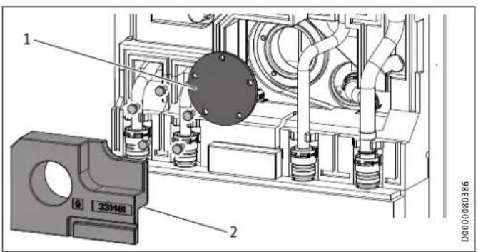
text_image
1 2 33M81 D00000803861 Blank flange
2 Insulation segment
Remove the insulation segment in front of the flange plate.
▶ Remove the blank flange.
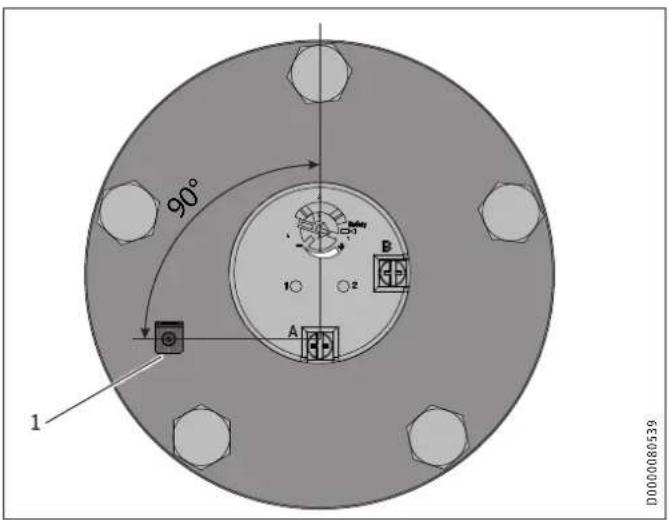
text_image
90° 1 1 A B D0000805391 Earthing contact PE
▶ Move the auxiliary heating element into the correct installation position. Use the position of the earthing contact as a guide.
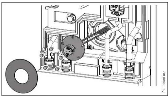
natural_image
Technical line drawing of a mechanical assembly with gears and housing (no text or symbols)▶ Place the insulation mat (included in the standard delivery for the auxiliary heating element) on the thermostat.
▶ Insert the insulation mat between the flange plate and cable.
▶ Install the auxiliary heating element. Observe the tightening torque (see chapter "Installation / Specification / Accessories").
Electrical connection HSBC 3-HE
In the delivered condition, the 3 wires for connecting the auxiliary heating element are connected to a prefitted terminal and earthing tab.
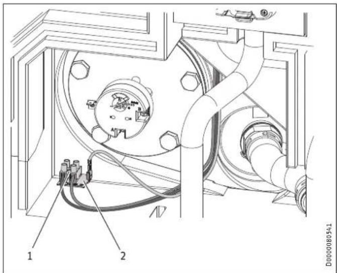
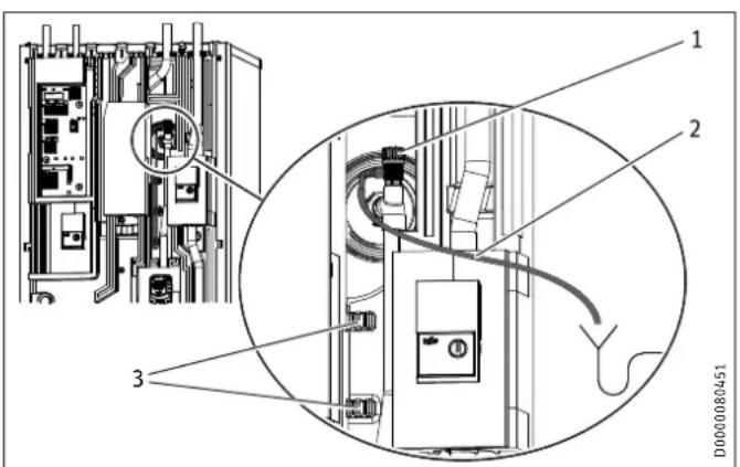
text_image
1 2 D00000805411 Terminal
2 Earthing tab
▶ Disconnect the 3 wires from the terminal and the earthing tab.
▶ Remove the terminal and earthing tab.
D0000080544
▶ Connect the 3 wires to the auxiliary heating element as shown.
A BK / BN
B BU
PE GNYE
Note
The auxiliary heating element standard delivery includes two identical wiring diagram labels for covering "HSBC 3-HE (accessory X2.11)" on the wiring diagram:
- On the back of the front casing
- In these instructions (see chapter "Installation / Specification / Wiring diagram")
▶ After installation of the auxiliary heating element, affix the wiring diagram labels in the corresponding places.
▶ Wire up the auxiliary heating element (see chapter "Installation / Electrical connection / Auxiliary heating element").
Setting HSBC 3-HE
3
1
D0000080540
1 Temperature selector for the auxiliary heating element
▶ Turn the temperature selector anti-clockwise as far as it will go to set the maximum temperature (65±5 °C).
10.2.4 Hydraulic connection

Note
▶ Observe the details specified in the chapter "Installation / Specification / Hydraulic diagrams".
10.3.2 Installing the pipe assembly (accessory) if required

WARNING Electrocution
Before starting work on the appliance, disconnect all poles from the power supply and drain the DHW cylinder.
▶ Thoroughly flush the pipes before connecting the heat pump. Foreign bodies (e.g. welding pearls, rust, sand, sealant, etc.) can impair the operational reliability of the heat pump.
▶ Install the heating water pipes (see chapter "Specification / Dimensions and connections").

Note
The following diagrams show pipe assembly RBS-SBC (see chapter "Specification / Dimensions and connections").
10.3 DHW connection and safety assembly
10.3.1 Safety instructions

Material losses
The maximum permissible pressure must not be exceeded (see chapter "Specification / Data table").

Material losses
Operate the appliance only with pressure-tested taps.
Cold water line
Galvanised steel, stainless steel, copper and plastic are approved materials.

Material losses
A safety valve is required.
Stainless steel, copper and plastic are approved materials.
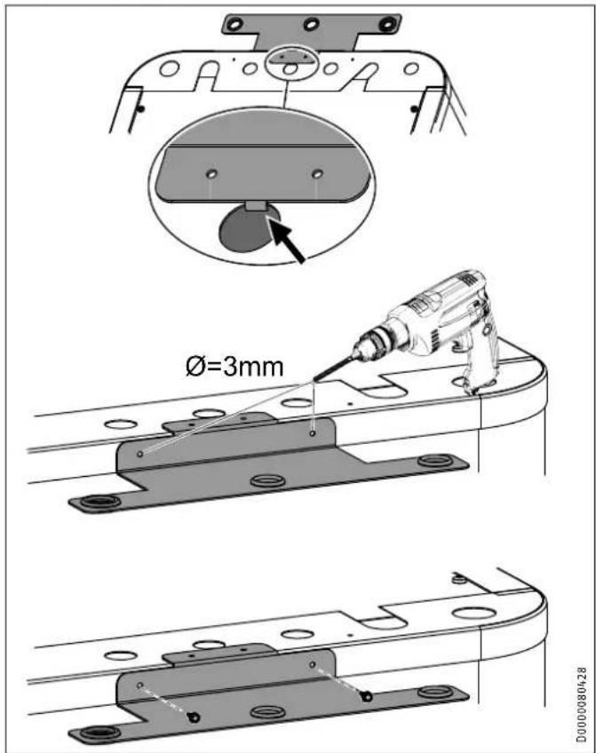
text_image
Ø=3mm D0000080428▶ Hook the retainer for the connection pipes into the top centre of the appliance.
▶ Use the retainer as a drilling template and pre-drill the fixing holes.
▶ Secure the retainer with the screws.
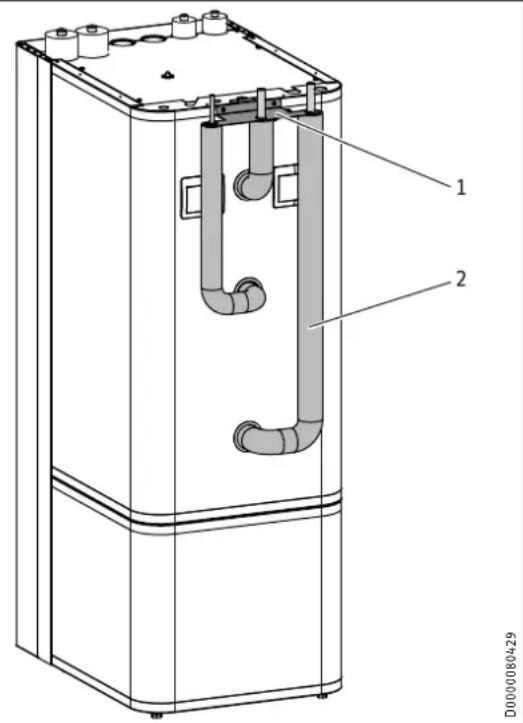
text_image
1 2 D0000804291 Retainer
2 Insulated connection pipes
▶ Install the connection pipes in sequence, starting on the left or right depending on the positioning of the appliance.
▶ Insert the connection pipes through the retainer from below.
▶ Secure the connections to the appliance using the union nut
▶ Connect the pipes of the pipe assembly to the domestic pipe work system.
10.3.3 Installing the DHW circulation line, if applicable
A DHW circulation line with external DHW circulation pump can be fitted to the DHW circulation connection (see chapter "Specification / Dimensions and connections").
▶ Remove the sealing cap from the DHW circulation connection (see chapter "Specification / Dimensions and connections").
▶ Connect the DHW circulation line.
10.3.4 DHW connection and safety assembly
▶ Flush the pipes thoroughly.
▶ Install the DHW outlet line and the cold water inlet line (see chapter "Specification / Dimensions and connections"). Connect the hydraulic connections with flat gaskets.
▶ Install a type-tested safety valve in the cold water inlet line. Please note that, depending on the supply pressure, you may also need a pressure reducing valve.
▶ Size the drain pipe so that water can drain off unimpeded when the safety valve is fully opened.
▶ The safety valve drain aperture must remain open to atmosphere.
▶ Install the safety valve drain pipe with a constant fall to the drain.
10.4 Filling the system
Heating circuit water quality
Carry out a fill water analysis before filling the system. This analysis may, for example, be requested from the relevant water supply utility.
To avoid damage as a result of scaling, it may be necessary to soften or desalinate the fill water. The fill water limits specified in chapter "Specification / Data table" must always be observed.
▶ Recheck these limits 8-12 weeks after commissioning and during the annual system service.

Note
With a conductivity >1000 S/cm, desalination treatment is recommended in order to avoid corrosion.

Note
If you treat the fill water with inhibitors or additives, the same limits apply as for desalination.

Note
Suitable appliances for water softening, as well as for filling and flushing heating systems, can be obtained via trade suppliers.

Material losses
Never switch on the power before filling the system.
£0.4.1 Filling the heating system
natural_image
Technical line drawing of a mechanical assembly with an inset close-up showing a circular component detail (no text or symbols)▶ Fill the heating system via the drain valve.
▶ Vent the pipework.
▶ Filling the DHW cylinder via the "cold water inlet" connection.
▶ Open all downstream draw-off valves until the appliance is full and the pipework is free of air.
▶ Adjust the flow rate. For this, observe the maximum permissible flow rate with a fully opened tap (see chapter "Specification / Data table"). If necessary reduce the flow rate at the butterfly valve of the safety assembly.
▶ Carry out a tightness check.
▶ Check the safety valve.
10.5 Venting the appliance
text_image
Technical diagram of an electrical enclosure with labeled components and a magnified view showing internal wiring connections.1 Air vent valve
2 Vent hose
3 Hose attachment
▶ Detach the vent hose from the hose attachment.
▶ Hang the free end of the vent hose in a container.
▶ To ventilate, open the air vent valve.
▶ After ventilation, close the air vent valve.
▶ Secure the vent hose.
11. Electrical connection

WARNING Electrocution
Carry out all electrical connection and installation work in accordance with relevant regulations.
Before any work on the appliance, disconnect all poles from the power supply.

WARNING Electrocution
The connection to the power supply must be in the form of a permanent connection. Ensure the appliance can be separated from the power supply by an isolator that disconnects all poles with at least 3 mm contact separation. This requirement can be met by using contactors, circuit breakers, fuses/MCBs, etc.

Material losses
Provide separate fuses for the two power circuits of the appliance and the control unit.

Material losses
Observe the type plate. The specified voltage must match the mains voltage.

Note
Leakage currents of up to 5 mA may occur.

Note
You must have permission to connect the appliance from the relevant power supply utility.
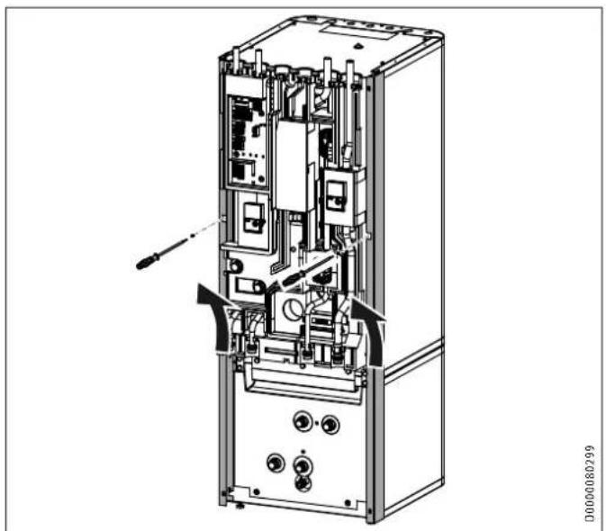
The terminal box of the appliance is located behind the front casing (see chapter "Preparations / Transport and handling / Removing / Fitting the front casing").
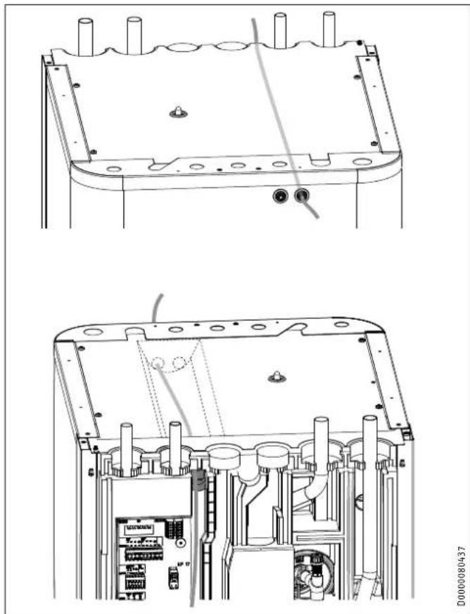
natural_image
Technical line drawing of an electronic device showing internal components and mounting brackets (no text or symbols)▶ Route all power cables and sensor leads into the appliance XE03 through the cable entry.
▶ Connect the power cables and sensor leads as detailed below.
Install cables with the following cross-sections in accordance with the respective fuse protection:
Fuse protection Assignment Cable cross-section
B 16 A Control 1.5 mm²
11.1 Control voltage

Material losses
▶ Only connect energy efficient circulation pumps approved by us to the pump connections.
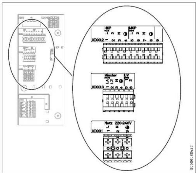
text_image
X0032 - N N + B S T S Mischer X0033 - N N + B S Netz 220-240V X0031 - N N D0000080432XD03.1 Control terminal
XD03.2 Control terminal
XD03.3 Control terminal
Earth terminal, control unit
XD03.1 Control terminal
Power supply Mains buffer charging pump
220-240 V
XD03.2 Control terminal
HKP Heating circuit pump
MKP Mixer circuit pump, heating circuit 2

Note
At terminals XD03.2 HKP/MKP, you can install a temperature limiter for the underfloor heating system by removing the jumper between L and 2.
XD03.3 Control terminal
Mixer Mixer, servomotor, heating circuit 2
UV Diverter valve, heating/DHW
11.2 Safety extra low voltage
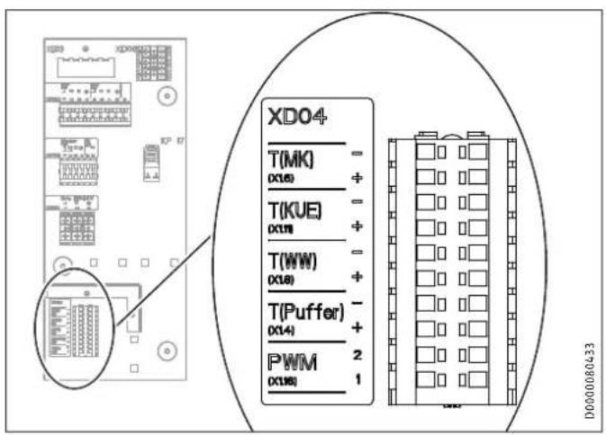
text_image
XDO4 T(MK) (X16) T(KUE) (X18) T(WW) (X18) T(Puffer) (X14) PWM (X18) D000080433XD04 Terminal, safety extra low voltage
| T(MK) | Mixer circuit temperature sensor for HSBC 3-HKM (optional) |
T(KUE) Temperature sensor for area cooling (optional)
T(WW) DHW temperature sensor
T(Puffer) Temperature sensor, buffer cylinder
PWM Control by WPM
Control by WPM via PWM signal
▶ Observe the information in the operating and installation instructions of the WPM heat pump manager.
11.3 Power supply for auxiliary heating element

Note
The "Heater terminal" (XD06.1) can only be assigned when the optional HSBC 3-HE auxiliary heating element is installed.
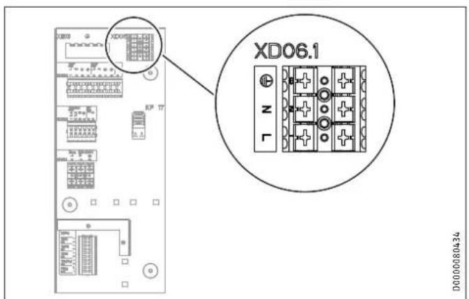
text_image
XD06.1 D0000080434XD06.1 Heater terminal (accessories HSBC 3-HE)
11.4 Sensor installation

Note
The temperature sensor needs to be replaced on combined appliance system HSBC 300 L cool with WPF / WPF cool.
▶ Use the PTC temperature sensor that was included in the standard delivery of the heat pump.
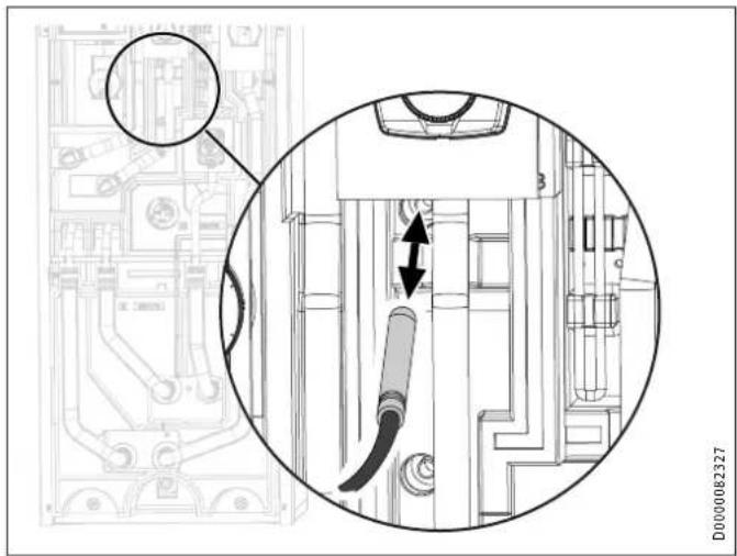
text_image
Technical diagram showing a mechanical assembly with labeled components and directional arrows indicating movement or flow.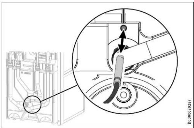
natural_image
Technical diagram showing a mechanical assembly with an inset close-up of a lever mechanism (no text or symbols present)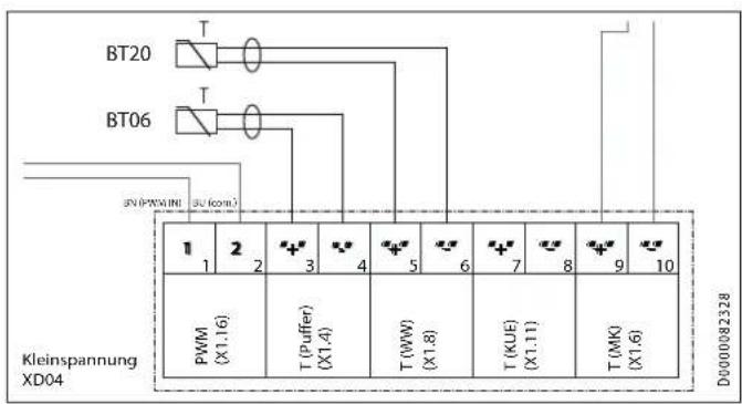
text_image
BT20 BT06 SN (PWM IN) SU (com.) 1 2 3 4 5 6 7 8 9 10 PWM (X1.16) T (Puffer) (X1.4) T (WW) (X1.8) T (KUE) (X1.11) T (MK) (X1.6) D0000082328 Kleinspannung XD04Appliances concerned:
- 238826
HSBC 300 L cool
- 232909 - 232912
WPF 04 - WPF 10
- 232915 - 232918 WPF 04 cool - WPF 10 cool
11.4.1 Temperature sensor for cooling (accessory), if required
Cooling requires the fitting of a temperature sensor, available as an accessory.
▶ Remove the front casing (see chapter "Preparations / Transport and handling / Removing / fitting the front casing").
natural_image
Technical diagram showing a mechanical assembly with a magnified inset view of a rotating component (no text or symbols present)▶ Insert the temperature sensor into the sensor well "Sensor heat pump cooling, optional".
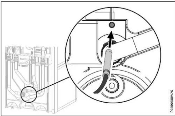
natural_image
Technical line drawing of a mechanical or electrical component assembly (no text or symbols visible)▶ Lay the sensor lead in the guide groove provided for this purpose in the insulation segment.
▶ Connect the temperature sensor to T(KUE) of terminal XD04 of the appliance.
12. Commissioning
Our customer support can assist with commissioning, which is a chargeable service.
If the appliance is intended for commercial use, observe the rules of the relevant Health & Safety at Work Act during commissioning. For further details, check with your local authorising body (in Germany, for example, this is the TÜV).
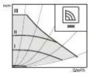
12.1 Wilo-Para .../Sc circulation pumps
LED indicators
| Operation indicator:LED illuminates green in normal operationLED illuminates/lashes when there is a fault | |
| display of selected control mode p-v, p-c and constant speed | |
| display of selected curve (I, II, III) within the control mode | |
| Combinations of LED displays for venting function, manual re-start and key lock |
Operating button
| Press |
| To select control mode |
| To select curve (I, II, III) within the control mode |
| Press and hold |
| To activate venting function (press for 3 seconds) |
| For manual restart (press for 5 seconds) |
| To lock/unlock keys (press for 8 seconds) |
Control modes and functions
| Variable differential pressure Δp-v (I, II, III) | Recommended for two-pipe heating systems with radiators to reduce flow noise at thermostatic valves |
| The pump reduces the delivery head by a half when flow rate drops in pipework. Saves energy by matching the delivery head to the flow rate demand and the lower flow velocities. Choice of three pre-defined curves (I, II, III). | |
| Constant pressure differential Δp-c (I, II, III) | Recommended for underfloor heating systems or with large-diameter pipework and for all applications with a non-varying pipework curve (e.g. cylinder charging pumps) and single-pipe heating systems with radiators |
| The control system keeps the set delivery head constant, irrespective of delivered flow rate. Choice of three pre-defined curves (I, II, III). | |
| Constant speed (I, II, III) | Recommended for systems with unchanging system resistance which require a constant throughput. |
| The pump runs at three preset fixed speed levels (I, II, III). | |
| NoteFactory setting: Constant speed, curve III |
Venting
| Fill the system properly and ventilate it If the pump is not ventilated automatically: Activate the venting function via the operating button, press button for 3 seconds, then release it. Venting function starts (duration 10 minutes). The top and bottom rows of LEDs flash alternately every second. To cancel, press the operating button for 3 seconds. | |
| Note After venting, the LED indicator displays the previously set pump values. |
Setting control modes
| Selecting the control mode | The LEDs for the control modes and associated curves illuminate one after the other. |
| Briefly press the operating button (for approx. 1 second). | |
| LEDs indicate the current selected control mode and curve (see following table). |
| Operating button | LED indicator Control mode Curve | ||
| 1x | Constant speed | II | |
| 2x | Constant speed | I | |
| 3x | Variable differential pressure Δp-v | III | |
| 4x | Variable differential pressure Δp-v | II | |
| 5x | Variable differential pressure Δp-v | I | |
| 6x | Constant differential pressure Δp-c | III | |
| 7x | Constant differential pressure Δp-c | II | |
| 8x | Constant differential pressure Δp-c | I | |
| *9x | Constant speed | III | |
(*) Pressing the button for the 9th time in succession returns the system to the factory setting (constant speed, curve III).
12.2 Appliance handover
Explain the appliance function to users and familiarise them with how it works.
▶ Make users aware of potential dangers.
▶ Hand over these instructions.
13. Appliance shutdown

Material losses
Observe the temperature application limits and the minimum circulation volume on the heat consumer side (see chapter "Specification / Data table").

Material losses
Drain the system when there is a risk of frost and the heat pump is completely switched off (see chapter "Maintenance / Draining the DHW cylinder").
▶ If you take the system out of use, set the heat pump manager. Replacing the signal anode
to standby so that the safety functions that protect the appliance (e.g. frost protection) remain active.
Hot water may escape during draining.
▶ Close the shut-off valve in the cold water inlet line.
▶ Open the hot water taps on all draw-off points.
▶ Empty the DHW cylinder via the "cold water inlet" connection.
Cleaning and descaling the DHW cylinder

Material losses
Never use descaling pumps or descaling agents to clean the cylinder.
▶ Clean the appliance through the inspection port.
For the torque of the flange screws, see chapter "Specification / Dimensions and connections".
▶ Replace the signal anode if it becomes depleted.
14. Maintenance

WARNING Electrocution
Carry out all electrical connection and installation work in accordance with relevant regulations.

WARNING Electrocution
Before any work on the appliance, disconnect all poles of the appliance from the power supply.
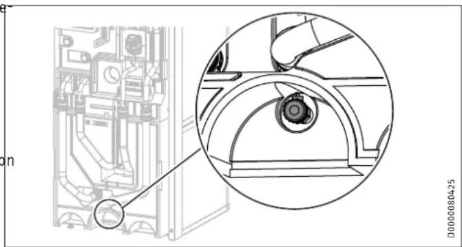
Draining the buffer cylinder
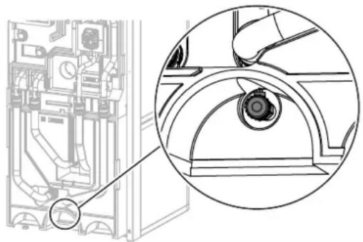
natural_image
Technical line drawing of a mechanical assembly with an inset close-up showing a circular detail (no text or symbols)D0000080425
▶ Drain the buffer cylinder via the drain valve.
15. Specification
15.1 Dimensions and connections
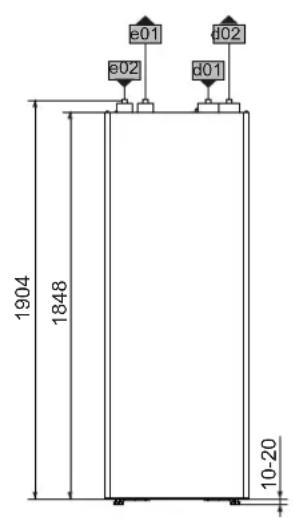
text_image
1904 1848 10-20 Ø01 Ø02 Ø01 Ø02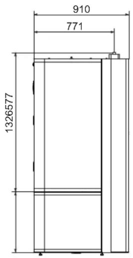
text_image
910 771 1326577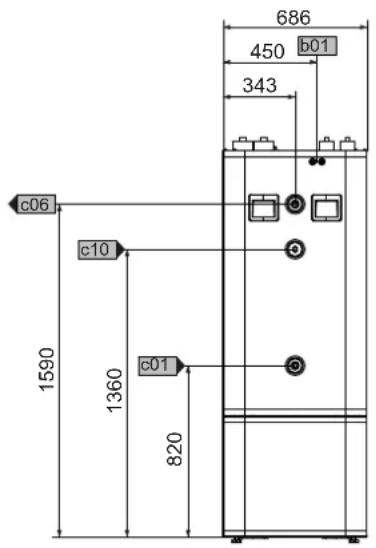
text_image
686 450 b01 343 c06 c10 1590 1360 c01 820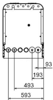
text_image
93 193 493 593D0000077428
| HSBC 300 cool HSBC 300 L cool | |||||
| b01 | Entry electrical cables | ||||
| c01 | Cold water inlet | Male thread | G 1 | G 1 | |
| c06 | DHW outlet | Male thread | G 1 | G 1 | |
| c10 | DHW circulation | Male thread | G 1/2 | G 1/2 | |
| d01 | Heat pump flow | Diameter | mm | 28 | 28 |
| d02 | Heat pump return | Diameter | mm | 28 | 28 |
| e01 | Heating flow | Diameter | mm | 22 | 22 |
| e02 | Heating return | Diameter | mm | 22 | 22 |
Other dimensions and connections
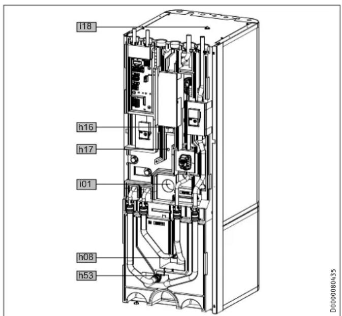
text_image
i18 h16 h17 i01 h08 h53 D000080435| HSBC 300 cool HSBC 300 L cool | |||||
| h08 | Sensor heat pump cooling, optional | Diameter | mm | 9.5 | 9.5 |
| h16 | Sensor DHW | Diameter | mm | 9.5 | 9.5 |
| h17 | Sensor, DHW, optional | Diameter | mm | 9.5 | 9.5 |
| h53 | Sensor heating | Diameter | mm | 9.5 | 9.5 |
| i01 | Flange | External diameter | mm | 140 | 140 |
| Torque | Nm | 45 | 45 | ||
| i18 | Protective anode | Female thread | G 1 1/4 | G 1 1/4 | |
15.1.1 HSBC 3-HKM accessories
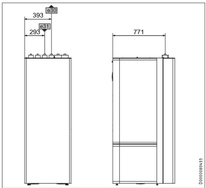
text_image
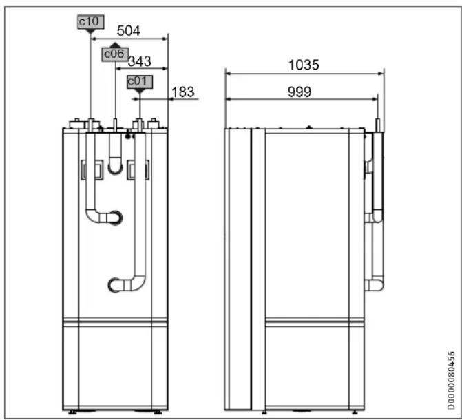
393 e30 e31 293 771 D000008045515.1.2 Accessories RBS-SBC
text_image
c10 504 c06 343 c01 183 1035 999 D000080456| HSBC 3-HKM | RBS-SBC | ||||
| c01 | Cold water inlet | Diameter | mm | 22 | 22 |
| c06 | DHW outlet | Diameter | mm | 22 | 22 |
| c10 | DHW circulation | Diameter | mm | 12 | 12 |
| e30 | Heating flow, mixed | Diameter | mm | 22 | 22 |
| e31 | Heating return, mixed | Diameter | mm | 22 | 22 |
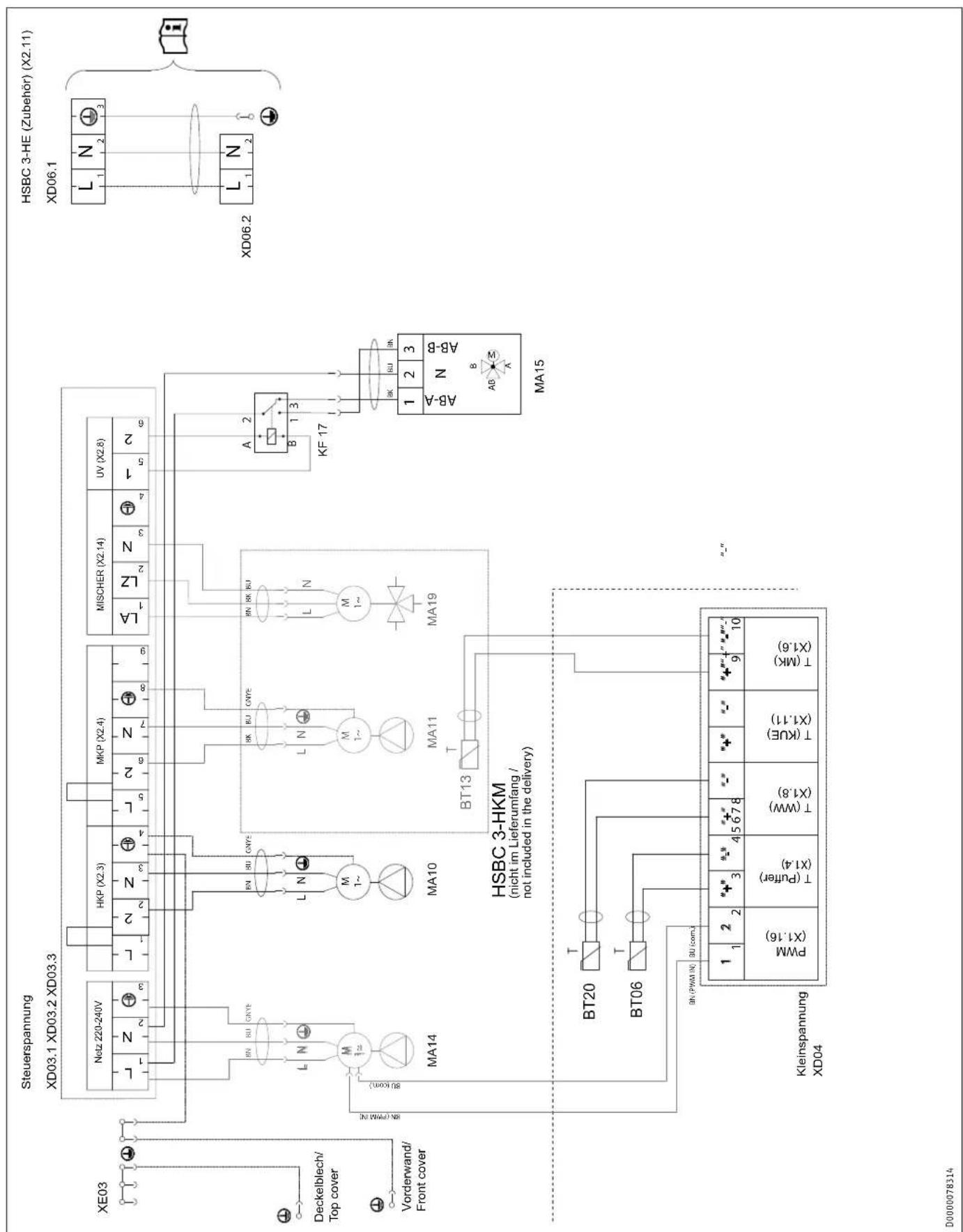
15.2 Wiring diagram
flowchart
graph TD
    subgraph "Steuerspannung"
        A["Steuer Spannung XD03.1"] --> B["Steuer Spannung XD03.2"]
        B --> C["Steuer Spannung XD03.3"]
    end

    subgraph "HSBC 3-HKM"
        D["HSBC 3-HE (Zubehör) (X2.11)"] --> E["HSBC 3-HE (Zubehör) (X2.11)"]
    end

    subgraph "Kleinspannung XD04"
        F["Steuer Spannung XD04"] --> G["Steuer Spannung XD04"]
    end

    subgraph "Deckelblech/Top cover"
        H["Deckelblech/Top cover"] --> I["Vorderwand/Front cover"]
    end

    subgraph "HKS" (L, N, 1, 2, 3) --> J["Steuer Spannung X2.3"]
    K["HKP (X2.3)"] --> L["Steuer Spannung X2.4"]
    M["MKP (X2.4)"] --> N["Steuer Spannung X2.4"]
    O["MISCHER (X2.14)"] --> P["Steuer Spannung X2.8"]
    Q["VA (LA)"] --> R["Steuer Spannung X2.8"]
    S["VA (LA)"] --> T["Steuer Spannung X2.8"]
    U["VA (LA)"] --> V["Steuer Spannung X2.8"]
    W["A (B)"] --> X["Steuer Spannung X2.8"]
    Y["KF 17"] --> Z["Steuer Spannung X2.8"]
    AA["KA"] --> AB["Steuer Spannung X2.8"]
    AC["BU"] --> AD["Steuer Spannung X2.8"]
    AE["BI"] --> AF["Steuer Spannung X2.8"]
    AG["KU"] --> AH["Steuer Spannung X2.8"]
    AI["KU"] --> AJ["Steuer Spannung X2.8"]
    AK["KU"] --> AL["Steuer Spannung X2.8"]
    AM["KU"] --> AN["Steuer Spannung X2.8"]
    AO["KU"] --> AP["Steuer Spannung X2.8"]
    AQ["KU"] --> AR["Steuer Spannung X2.8"]
    AS["KU"] --> AT["Steuer Spannung X2.8"]
    AU["KU"] --> AV["Steuer Spannung X2.8"]
    AW["XN-PWM IN"] --> AX["Steuer Spannung X2.8"]
    AY["T (Puffer) (X1.4)"] --> AZ["Steuer Spannung X2.8"]
    BA["T (WW) (X1.8)"] --> BB["Steuer Spannung X2.8"]
    BC["T (KUE) (X1.11)"] --> BD["Steuer Spannung X2.8"]
    BE["T (MK) (X1.6)"] --> BF["Steuer Spannung X2.8"]
    BG["XN-PWM IN"] --> BH["Steuer Spannung X2.8"]
    BI["XN-PWM IN"] --> BJ["Steuer Spannung X2.8"]
    BK["XN-PWM IN"] --> BL["Steuer Spannung X2.8"]
    BM["XN-PWM IN"] --> BN["Steuer Spannung X2.8"]
    BO["XN-PWM IN"] --> BP["Steuer Spannung X2.8"]
    BZ["XN-PWM IN"] --> CA["Steuer Spannung X2.8"]
    CB["XN-PWM IN"] --> CC["Steuer Spannung X2.8"]
    DD["XN-PWM IN"] --> DE["XN-PWM IN"]
    BEX["XN-PWM IN"] --> BFX["XN-PWM IN"]

    subgraph "HKS 3-HKM (nicht im Lieferumfang / not included in the delivery)"
        F --> G
        H --> I
        J --> K
        L --> L
        M --> M
        N --> N
        O --> O
        P --> P
        Q --> Q
        R --> R
        S --> R
        T --> T
        U --> U
        V --> V
        W --> W
        X --> W
        Y --> Y
        Z --> Z
        AA --> AA
        AB --> AB
        AC --> AC
        AD --> AD
        AE --> AE
        AF --> AF
        AG --> AG
        AH --> AH
        AI --> AI
        AJ --> AJ
        AK --> AK
        AL --> AL
        AM --> AM
        AN --> AN
        AO --> AO
        AP --> AP
        AQ --> AQ
        AR --> AR
        AS --> AS
        AT --> AT
        AU --> AU
        AV --> AV
        AW --> AW
        AX --> AX
        AY --> AY
        AZ --> AZ
        BA --> BA
        BB --> BB
        BC --> BC
        DA --> DA
        AE --> AE
        AF --> AF
        AG --> AG
        AH --> AH
        AI --> AI
        AJ --> AJ
        AK --> AK
        AL --> AL
        AM --> AM
        AN --> AN
        AO --> AO
        AP --> AP
        AQ --> AQ
        AR --> AR
        AS --> AS
        AT --> AT
        AU --> AT
        AV --> AV
        AW --> AW
        AX --> AX
        AY --> AY
        AZ --> AZ
        BA --> BA
        BB --> BB
        BC --> BC
        AD --> AD
        AE --> AE
        AF --> AF
        AG --> AG
        AH --> AH
        AI --> AH
        AJ --> AH
        AK --> AH
        AL --> AL
        AM --> AL
        AN --> AN
        AO --> AO
        AP --> AP
        AQ --> AP
        AR --> AP

    end
BT06 Temperature sensor, heat pump buffer cylinder
BT20 Temperature sensor, DHW cylinder
BT13 Temperature sensor HP flow HC2 (accessories HSBC 3-HKM)
MA10 Motor, pump, heating circuit
MA11 Motor, pump, heating circuit 2
MA14 Motor, buffer charging pump (not for HSBC 300 L cool and TSBC 300 L plus)
MA15 Motor, diverter valve, heating, DHW
MA19 Motor, mixing valve heating circuit 2
XD04 LV terminal
XD06.1 Heater terminal (accessories HSBC 3-HE)
XD06.2 Heater terminal (accessories HSBC 3-HE)
XD03.1 Control terminal (mains buffer charging pump)
XD03.2 Control terminal (heating circuit pump, pump heating circuit 2)
XD03.3 Control terminal (mixer heating circuit 2, diverter valve)
KF17 Relay, diverter valve, heat source
XE03 Earth terminal, control unit
15.3 Hydraulic diagrams
HSBC 300 cool
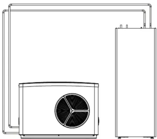
natural_image
Technical line drawing of a dual air conditioning unit with fan and cooling unit (no text or symbols)D0000080569
HSBC 300 L cool

natural_image
Technical line drawing of a dual-chamber industrial system with pipes and control panels (no text or symbols)D0000080571D0000080570
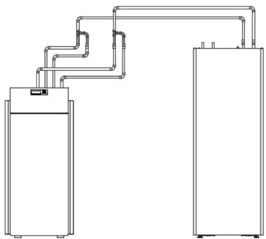
natural_image
Pure technical line drawing of two vertical rectangular units connected by pipes, no text or symbols present15.4 Energy consumption data
Product datasheet: DHW cylinder to Regulation (EU) No 812/2013
| HSBC 300 cool HSBC 300 L cool | |||
| 236686 238826 | |||
| Manufacturer | STIEBEL ELTRON | STIEBEL ELTRON | |
| Designation | HSBC 300 cool | HSBC 300 L cool | |
| Energy efficiency class | B | B | |
| Standby losses | W | 61 | 61 |
| Cylinder capacity | I | 291 | 291 |
15.5 Data table
| HSBC 300 cool | HSBC 300 L cool | ||
| 236686 | 238826 | ||
| Hydraulic data | |||
| Nominal capacity, DHW cylinder | l | 270 | 270 |
| Nominal capacity, buffer cylinder | l | 100 | 100 |
| Surface area, indirect coil | m^2 | 3.3 | 3.3 |
| Capacity, indirect coil | l | 21 | 21 |
| External available pressure differential, circulation pump/heat pump at 1.0 m^3/h | hPa | 656 | |
| External available pressure differential, circulation pump/heat pump at 1.5 m^3/h | hPa | 527 | |
| External available pressure differential, circulation pump/heat pump at 2.0 m^3/h | hPa | 210 | |
| External available pressure differential, circulation pump / heating circuit 1 at 1.0 m^3/h | hPa | 725 | 725 |
| External available pressure differential, circulation pump / heating circuit 1 at 1.5 m^3/h | hPa | 663 | 663 |
| External available pressure differential, circulation pump / heating circuit 1 at 2.0 m^3/h | hPa | 444 | 444 |
| External available pressure differential, circulation pump / heating circuit 2 (optional) at 1.0 m^3/h | hPa | 665 | 665 |
| External available pressure differential, circulation pump / heating circuit 2 (optional) at 1.5 m^3/h | hPa | 518 | 518 |
| External available pressure differential, circulation pump / heating circuit 2 (optional) at 2.0 m^3/h | hPa | 189 | 189 |
| Application limits | |||
| Max. permissible pressure, DHW cylinder | MPa | 1.0 | 1.0 |
| Test pressure, DHW cylinder | MPa | 1.5 | 1.5 |
| Max. flow rate | l/min | 25 | 25 |
| Max. permissible pressure, buffer cylinder | MPa | 0.3 | 0.3 |
| Test pressure, buffer cylinder | MPa | 0.45 | 0.45 |
| Max. permissible temperature | °C | 85 | 85 |
| Max. permissible temperature, primary side | °C | 75 | 75 |
| Heating water quality requirements | |||
| Water hardness | °dH | ≤3 | ≤3 |
| pH value (with aluminium fittings) | 8.0-8.5 | 8.0-8.5 | |
| pH value (without aluminium fittings) | 8.0-10.0 | 8.0-10.0 | |
| Conductivity (softening) | μS/cm | <1000 | <1000 |
| Conductivity (desalination) | μS/cm | 20-100 | 20-100 |
| Chloride | mg/l | <30 | <30 |
| Oxygen 8-12 weeks after filling (softening) | mg/l | <0.02 | <0.02 |
| Oxygen 8-12 weeks after filling (desalination) | mg/l | <0.1 | <0.1 |
| Power consumption | |||
| Max. power consumption, charging pump | W | 60 | |
| Max. power consumption, circulation pump on the heating side | W | 60 | 60 |
| Energy data | |||
| Standby energy consumption/24 h at 65 °C | kWh | 1.5 | 1.5 |
| Energy efficiency class | B | B | |
| Electrical data | |||
| Frequency | Hz | 50 | 50 |
| Versions | |||
| IP rating | IP20 | IP20 | |
| Dimensions | |||
| Height | mm | 1918 | 1918 |
| Width | mm | 680 | 680 |
| Depth | mm | 910 | 910 |
| Height when tilted | mm | 2123 | 2123 |
| Weights | |||
| Weight, full | kg | 641 | 639 |
| Weight, empty | kg | 250 | 248 |
Further details
| HSBC 300 cool HSBC 300 L cool236686 238826 | |||
| Maximum altitude for installation | m | 2000 | 2000 |
15.6 Accessories
Pipe assembly RBS-SBC
| RBS-SBC238827 | ||
| Connections | ||
| Cold water connection | mm | 22 |
| DHW connection | mm | 22 |
| DHW circulation connection | mm | 12 |
| Versions | ||
| Suitable for | ...SBC 300 cool / plus and 300 L cool /plus | |
Pump assembly HSBC 3-HKM
| HSBC 3-HKM | ||
| 238825 | ||
| Connections | ||
| Heating circuit connection | mm | 22 |
Auxiliary heating element HSBC 3-HE
| HSBC 3-HE | ||
| 200025 | ||
| Electrical data | ||
| Connected load ~ 230 V | kW | 2 |
| Rated voltage | V | 230 |
| Phases | 1/N/PE | |
| Frequency | Hz | 50 |
| Application limits | ||
| Temperature setting range | °C | 35-65 |
| Max. permissible pressure | MPa | 1.0 |
| Minimum cylinder diameter | mm | 500 |
| Minimum cylinder volume | l | 150 |
| Dimensions | ||
| Flange external diameter | mm | 140 |
| Immersion depth | mm | 480 |
| Torque | Nm | 45 |
| Weights | ||
| Weight | kg | 2 |
Guarantee
The guarantee conditions of our German companies do not apply to appliances acquired outside of Germany. In countries where our subsidiaries sell our products a guarantee can only be issued by those subsidiaries. Such guarantee is only granted if the subsidiary has issued its own terms of guarantee. No other guarantee will be granted.
We shall not provide any guarantee for appliances acquired in countries where we have no subsidiary to sell our products. This will not affect warranties issued by any importers.
Environment and recycling
We would ask you to help protect the environment. After use, dispose of the various materials in accordance with national regulations.
REMARQUES PARTICULIÈRES
UTILISATION
1.1 Documentation applicable 69
1.1 Documentation applicable
- WPL 10 AC
- WPL 15/20/25 AC(S)
- WPL 19/24 I
HSBC 300 L cool :
- WPL 09/17 ICS/IKCS classic
- WPL 19/24 IK
- WPF 04/05/07/10 (cool)
text_image
STIEBEL ELTRON No.: CXXKXCKXKXKX Made in Germany D000080280INSTALLATION
7. Sécurité
natural_image
Diagram showing a mechanical setup with a rotating component and a magnified view of a threaded bolt inside a spherical housing (no text or symbols)natural_image
Technical line drawing of a rectangular electronic device with a black arrow indicating a directional flow (no text or symbols present)text_image
Exploded view diagram of an electronic device showing internal components and labeled partsD0000080535
text_image
Technical diagram of an industrial equipment cabinet with labeled components and a magnified inset showing a device component.
Remarque
text_image
Technical diagram showing a computer tower with labeled components and a magnified view of the internal component being inserted.▶ Retirez l'élément isolant 1.
▶ Retirez l'élément isolant 2.

natural_image
Technical diagram showing a mechanical assembly with an inset close-up of a component, no visible text or symbols.natural_image
Technical line drawing of a mechanical or electrical component with pipes and connections (no text or symbols)natural_image
Cross-sectional diagram of a mechanical assembly with internal components and directional arrows (no text or labels)natural_image
Technical line drawing of a mechanical assembly with pipes and housing (no text or symbols)▶ Retirez les 4 flexibles hydrauliques.
▶ Retirez les 2 vis pour isolant.
▶ Retirez l'élément isolant 3.
natural_image
Technical line drawing of an internal electronic device with visible ports and components (no text or symbols)natural_image
Technical line drawing of an industrial machine or control unit with multiple ports and mounting brackets (no text or symbols visible)natural_image
Diagram of a mechanical assembly with a box and a component, showing an arrow indicating direction (no text or symbols present)natural_image
Technical line drawing of an electrical enclosure with internal components and wiring (no text or symbols)text_image
Technical diagram of an electronic device with labeled components and a magnified inset showing internal structure details.natural_image
Technical line drawing of a U-shaped mechanical component with a labeled dimension (no text or symbols beyond measurement label)natural_image
3D diagram of a mechanical component with an arrow indicating direction, no text or symbols presenttext_image
Technical diagram illustrating mechanical assembly and disassembly steps with labeled components and magnified viewstext_image
Technical diagram of an electrical enclosure with labeled components and wiring pathsDommages matériels
flowchart
graph TD
    subgraph XD03.2_XD03.3
        A["MKP (X2.4)"] --> B["LA 1"]
        A --> C["LZ 2"]
        A --> D["N 3"]
        A --> E["4"]
        F["MISCHER (X2.14)"] --> G["LA 1"]
        F --> H["LZ 2"]
        F --> I["N 3"]
        F --> J["4"]
    end

    subgraph XD04
        K["BT13"] --> L["T (MK) (X1.6)"]
        M["MA11"] --> N["M 1~"]
        O["MA19"] --> P["M 1~"]
    end

    style XD03.2_XD03.3 fill:#f9f,stroke:#333
    style XD04 fill:#ccf,stroke:#333
natural_image
Technical line drawing of a mechanical assembly with gears and shafts (no text or symbols)natural_image
Technical line drawing of an electrical enclosure with coiled wires and a central component (no text or symbols)natural_image
Technical line drawing of an electronic device showing internal components and mounting brackets (no text or symbols)text_image
XD08 XD09 XF 17 XD04 T(MK) DXLB T(KUE) DXLB T(WW) DXLB T(Puffer) DXL4 PWM DXLB =+ = + = + - 2 1 D0000080433natural_image
Technical diagram of a mechanical assembly with a magnified inset showing a cable inserted into a component (no text or symbols present)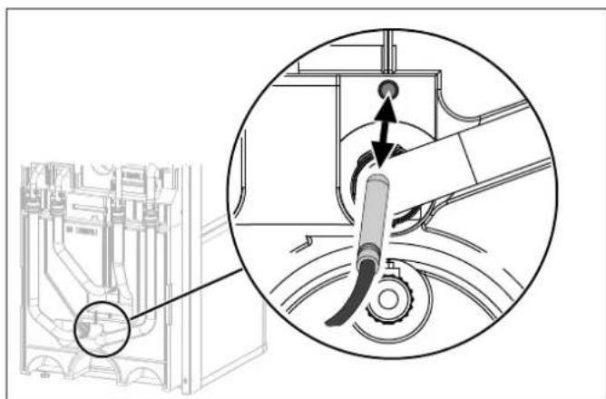
natural_image
Technical diagram showing a mechanical assembly with a magnified inset of the component (no text or symbols present)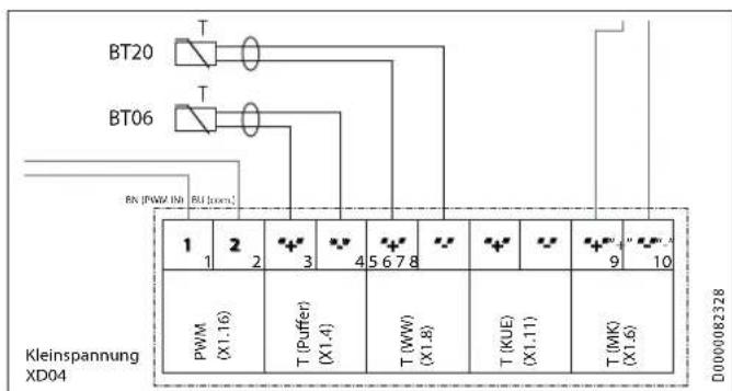
text_image
BT20 BT06 RN (PWM IN) RN (IQR) 1 2 3 4 5 6 7 8 9 10 PWM (X1.16) T (Puffer) (X1.4) T (WW) (X1.8) T (KUE) (X1.11) T (WK) (X1.6) D0000082328 Kleinspannung XD04natural_image
Technical diagram showing a mechanical assembly with an inset close-up of a component being inserted into a housing (no text or symbols present)natural_image
Technical line drawing of a mechanical or electrical component with pipes and housing (no text or symbols)Régime constant (I, II, III)
text_image
Diagram showing icons and labels for a software interface, including selection tools, zoom controls, and 3mm scale indicator.natural_image
Technical line drawing of a mechanical assembly with an inset close-up showing internal components (no text or symbols)natural_image
Technical line drawing of a dual air conditioning unit with fan and cooling unit (no text or symbols)D0000080569
HSBC 300 L cool

natural_image
Technical line drawing of a dual-chamber industrial system with pipes and control panels (no text or symbols)D0000080571D0000080570

natural_image
Pure technical line drawing of two vertical rectangular units connected by pipes, no text or symbols presentWAARSCHUWING verbranding
- WPL 10 AC
- WPL 15/20/25 AC(S)
- WPL 19/24 I
HSBC 300 L cool:
- WPL 09/17 ICS/IKCS classic
- WPL 19/24 IK
- WPF 04/05/07/10 (cool)
natural_image
Diagram showing a mechanical setup with a rotating component and a spherical component, no text or symbols present.natural_image
Technical line drawing of a rectangular electronic device with a black arrow indicating forward direction (no text or symbols present)text_image
Exploded view diagram of an electronic device showing internal components and labeled partsD0000080535
text_image
Technical diagram of an industrial equipment cabinet with labeled components and a magnified inset showing a device's view.
natural_image
Technical diagram showing a mechanical assembly with a magnified inset of a component detail (no text or symbols present)natural_image
Technical line drawing of a mechanical or electrical component with pipes and housing (no text or symbols)text_image
Technical diagram showing a device rear panel with labeled ports and a magnified view of the handle mechanism.natural_image
Cross-sectional diagram of a mechanical assembly with internal components and directional arrows (no text or labels)natural_image
Technical line drawing of a mechanical assembly with pipes and housing (no text or symbols)natural_image
Technical line drawing of an internal electronic device with visible ports and wiring (no text or symbols)natural_image
Technical line drawing of an industrial machine or control unit with multiple ports and mounting brackets (no text or symbols visible)natural_image
3D diagram of a mechanical component with a black arrow indicating direction, no text or symbols presentnatural_image
Technical line drawing of an electrical enclosure with internal components and wiring (no text or symbols)text_image
Technical diagram of an electronic device with labeled components and a magnified inset showing internal structure details.natural_image
Technical line drawing of a U-shaped mechanical component with a labeled section (no text or symbols beyond the label)natural_image
3D diagram of a mechanical component with an arrow indicating direction, no text or symbols present▶ Monteer isolatie-element 2.
▶ Monteer isolatie-element 1.
▶ Monteer de frontkap.
10. Montage
text_image
Technical diagram of a mechanical or electrical assembly with numbered components, likely for assembly or maintenance reference.text_image
Technical diagram illustrating mechanical assembly and disassembly steps with labeled parts and magnified viewsnatural_image
Technical line drawing of a mechanical assembly with gears and shafts (no text or symbols)natural_image
Technical line drawing of an electrical enclosure with coiled wires and a central component (no text or symbols)text_image
Technical diagram of a refrigerant or industrial device with labeled components 1 and 2D000080429
natural_image
Technical line drawing of a mechanical assembly with an inset close-up showing internal components (no text or symbols)text_image
Technical diagram of an electrical enclosure with labeled components and wiring connectionsnatural_image
Technical line drawing of an electronic device showing internal components and mounting brackets (no text or symbols)natural_image
Technical diagram showing a mechanical assembly with a magnified inset of the component (no text or symbols present)
text_image
BT20 BT06 BW (PWM IN) BU IOM 1 2 3 4 5 6 7 8 9 10 PWM (X1.16) T (PUFFER) (X1.4) T (WW) (X1.8) T (KUE) (X1.11) T (MK) (X1.6) D0000082328 Kleinspannung XD04Relevante toestellen:
- 238826
- 232909 - 232912
- 232915 - 232918
HSBC 300 L cool
WPF 04 - WPF 10
WPF 04 cool - WPF 10 cool
natural_image
Technical diagram showing a mechanical assembly with an inset close-up of a component being inserted (no text or symbols present)▶ Steek de temperatuursensor in de sensorhuls "Sensor WF koelen optioneel".

natural_image
Technical line drawing of a mechanical or electrical component with pipes and housing (no text or symbols)natural_image
Technical line drawing of a mechanical assembly with an inset close-up showing internal components (no text or symbols)Tap het buffervat af via de aftapkraan.
Warmwaterboiler aftappen

flowchart
graph TD
    subgraph HSBC_3_HKM
        A["BSB13"] --> B["BSB14"]
        C["BSB15"] --> D["BSB16"]
        E["BSB20"] --> F["BSB21"]
        G["BSB22"] --> H["BSB23"]
        I["BSB24"] --> J["BSB25"]
        K["BSB26"] --> L["BSB27"]
        M["BSB28"] --> N["BSB29"]
        O["BSB30"] --> P["BSB31"]
        Q["BSB32"] --> R["BSB33"]
        S["BSB34"] --> T["BSB35"]
        U["BSB36"] --> V["BSB37"]
        W["BSB38"] --> X["BSB39"]
        Y["BSB40"] --> Z["BSB41"]
        AA["BSB42"] --> AB["BSB43"]
        AC["BSB44"] --> AD["BSB45"]
        AE["BSB46"] --> AF["BSB47"]
        AG["BSB48"] --> AH["BSB49"]
        AI["BSB4A"] --> AJ["BA-B"]
    end

    subgraph HSBC_3_HE_Zubehör
        AK["HSBC 3-HE (Zubehör) (X2.11)"]
        AL["XD06.1"] --> AM["L1 N2 3"]
        AN["XD06.2"] --> AO["L1 N2"]
    end

    subgraph Steuerspannung
        AP["XE03"] --> AQ["Deckelblech/Top cover"]
        AR["Vorderwand/Front cover"] --> AS["M1~"]
        AT["Steuerspannung XD03.1 XD03.2 XD03.3"] --> AU["Netz 220-240V"]
        AV["HKP (X2.3)"] --> AW["L1 2 N3 4"]
        AX["MKP (X2.4)"] --> AY["L5 2 N7 8"]
        AZ["MISCHER (X2.14)"] --> BA["L1 LZ N3 4 1 5 2"]
        BB["UV (X2.8)"] --> BC["A1 2 B1 3"]
        BD["KF 17"] --> BE["B1 3"]
    end

    subgraph HC_Bayouk
        BF["MSK (X1.16)"] --> BG["PWM (X1.16)"]
        BH["T (Puffer) (X1.4)"] --> BI["T (Puffer) (X1.4)"]
        BJ["T (WW) (X1.8)"] --> BK["T (WW) (X1.8)"]
        BL["T (KUE) (X1.11)"] --> BM["T (KUE) (X1.11)"]
        BN["T (MK) (X1.6)"] --> BO["T (MK) (X1.6)"]
    end

    subgraph HC_Bayouk
        BP["MSK (X1.16)"] --> BQ["PWM (X1.16)"]
        BR["T (Puffer) (X1.4)"] --> BS["PWM (X1.16)"]
        BT["T (WW) (X1.8)"] --> BU["PWM (X1.16)"]
        BV["T (KUE) (X1.11)"] --> BW["PWM (X1.16)"]
    end

    subgraph HC_Bayouk
        CA["MSK (X1.16)"] --> CB["PWM (X1.16)"]
        CC["T (Puffer) (X1.4)"] --> CD["PWM (X1.16)"]
        DD["T (WW) (X1.8)"] --> DJ["PWM (X1.16)"]
        DK["T (KUE) (X1.11)"] --> DL["PWM (X1.16)"]
    end

    subgraph HC_Bayouk
        EM["MSK (X1.16)"] --> EN["PWM (X1.16)"]
        EO["MSK (X1.2)"] --> EP["PWM (X1.16)"]
    end

    subgraph HC_Bayouk
        AQ["MSK (X1.2)"] --> AR["PWM (X1.16)"]
        AS["T (Puffer) (X1.4)"] --> AT["PWM (X1.16)"]
        AU["T (WW) (X1.8)"] --> AV["PWM (X1.16)"]
        AW["T (KUE) (X1.11)"] --> AX["PWM (X1.16)"]
    end

    subgraph HC_Bayouk
        AY["MSK (X1.2)"] --> AZ["PWM (X1.16)"]
        BA["T (Puffer) (X1.4)"] --> BB["PWM (X1.16)"]
        BC["T (WW) (X1.8)"] --> BD["PWM (X1.16)"]
        BE["T (KUE) (X1.11)"] --> BF["PWM (X1.16)"]
    end

    subgraph HC_Bayouk
        BG["MSK (X1.2)"] --> BH
        BH --> BH
    end

    subgraph HC_Bayouk
        BH_0["BN BU GNYE"] --> BH_0
        BH_0_0["M 1~"] --> BH_0_0
        BH_0_0_MA14 --> BH_0_0
        BH_0_0_MA10 --> BH_0_0
        BH_0_0_MA10 --> BH_0_0
    end

    subgraph HC_Bayouk
        BH_0_0["M 1~"] --> BH_0_0
        BH_0_0_MA10 --> BH_0_0
        BH_0_0_MA10 --> BH_0_0
    end

    subgraph HC_Bayouk
        BH_0_0_MA10 --> BH_0_0
    end

    subgraph HC_Bayouk
        BH_0_0_MA10 --> BH_0_0
    end

    subgraph HC_Bayouk
        BH_0_0_MA10 --> BH_0_0
    end

    subgraph HC_Bayouk
        BH_0_0_MA10 --> BI["M 1~"]
    end

    subgraph HC_Bayouk
        BH_0_0_MA10 --> BI_MA10
    end

    subgraph HC_Bayouk
        BH_0_0_MA10 --> BI_MA10
    end

    subgraph HC_Bayouk
        BH_0_0_MA10 --> BI_MA19
    end

    subgraph HC_Bayouk
        BH_0_0_MA10 --> BI_MA9
    end

    subgraph HC_Bayouk
        BH_0_0_MA10 --> BI_MA9
    end

    subgraph HC_Bayouk
        BH_0_0_MA10 --> BI_MA9
    end

    subgraph HC_Bayouk
        BH_0_0_MA9 --> BI_MA9
    end

    subgraph HC_Bayouk
        BH_0_0_MA9 --> BI_MA9
    end

    subgraph HC_Bayouk
        BH_0_0_MA9 --> BI_MA9
    end

    subgraph HC_Bayouk
        BH_0_0_MA9 --> BI_MA9
    end

    subgraph HC_Bayouk
    BI_MA9 --> BI_MA9
    BI_MA9 --> BI_MA9
    BI_MA9 --> BI_MA9
    BI_MA9 --> BI_MA9
    BI_MA9 --> BI_MA9
    BI_MA9 --> BI_MA9
    BI_MA9 --> BI_MA9
    BI_MA9 --> BI_MA9
    BI_MA9 --> BI_MA9
    BI_MA9 --> BI_MA9

    subgraph HC_Bayouk
        BI_MA9 --> BI_MA9
    end

    subgraph HC_Bayouk
        BI_MA9 --> BI_MA9
    end

    subgraph HC_Bayouk
        BI_MA9 --> BI_MA9
    end

    subgraph HC_Bayouk
        BI_MA9 --> BI_MA9
    end

    subgraph HC_Bayouk
        BI_MA9 --> BI_MA9
    end

    subgraph HC_BayOUk
        BI_MA9 --> BI_MM_AI5
    end

    subgraph HC_BayOUk
        BI_MM_AI5 --> BI_MM_BI5
    end

    subgraph HC_BayOUk
        BI_MM_BI5 --> BI_MM_CI5
    end

    subgraph HC_BayOUk
        BI_MM_CI5 --> BI_MM_DI5
    end

    subgraph HC_BayOUk
        BI_MM_DI5 --> BI_MM_EI5
    end

    subgraph HC_BayOUk
        BI_MM_EI5 --> BI_MM_FI5
    end

    subgraph HC_BayOUk
        BI_MM_FI5 --> BI_MM_LN5
    end

    subgraph HC_BayOUk
        BI_MM_LN5 --> BI_MM_RN5
    end

    subgraph HC_BayOUk
        BI_MM_RN5 --> BI_MM_LN5
    end

    subgraph HC_BayOUk
        BI_MM_LN5 --> BI_MM_RN5
    end

    subgraph HC_BayOUk
        BI_MM_RN5 --> BI_MM_LN5
    end

    subgraph HC_BayOUk
        BI_MM_LN5 --> BI_MM_RN5
    end

    subgraph HC_BayCUk
        BI_MM_LN5 --> BI_MM_CI5
    end

    subgraph HC_BayCUk
        BI_MM_CI5 --> BI_MM_FI5
    end

    subgraph HC_BayCUk
        BI_MM_FI5 --> BI_MM_LN5
    end

    subgraph HC_BayCUk
        BI_MM_FI5 --> BI_MM_LN5
    end

    subgraph HC_BayCUk
        BI_MM_LN5 --> BI_MM_RN5
    end

    subgraph HC_BayCUk
        BI_MM_RN5 --> BI_MM_LN5
    end

    subgraph HC_BayCUk
        BI_MM_LN5 --> BI_MM_RN5
    end

    subgraph HC_BayCUk
        BI_MM_LN5 --> BI_MM_CI5
    end

    subgraph HC_BayCUk
        BI_MM_RN5 --> BI_MM_FI5
    end

    subgraph HC_BayCUk
        BI_MM_FI5 --> BI_MM_LN5
    end

    subgraph HC_BayCUk
        BI_MM_FI5 --> BI_MM_LN5
    end

    subgraph HC_BayCUk
        BI_MM_LN5 --> BI_MM_RN5
    end

    subgraph HC_BayUk
        BI_MM_LN5 --> BI_MM_RN5
    end

    subgraph HC_BayUk
        BI_MM_RN5 --> BI_MM_LN5
    end

    subgraph HC_BayUk
        BI_MM_LN5 --> BI_MM_RN5
    end

    subgraph HC_BayUk
        BI_MM_RN5 --> BI_MM_LN5
    end

    subgraph HC_BayUk
        BI_MM_LN5 --> BI_MM_RN5
    end

    subgraph HC_BayUk
        BI_MH_LN5 --> BI_MH_RN5
    end

    subgraph HC_BayUk
        BI_MH_LN5 --> BI_MH_RN5
    end

    subgraph HC_BayUk
        BI_MH_LN5 --> BI_MH_RN5
    end

    subgraph HC_BayUk
        BI_MH_LN5 --> BI_MH_RN5
    end

    subgraph HC_BayCUk
        BI_MH_LN5 --> BI_MH_RN5
    end

    subgraph HC_BayCUk
        BI_MH_LN5 --> BI_MH_RN5
natural_image
Technical line drawing of a dual air conditioning unit with fan and cooling unit (no text or symbols)D0000080569
HSBC 300 L cool
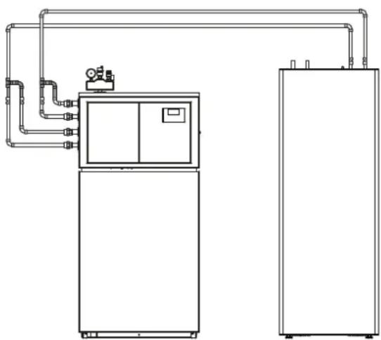
natural_image
Technical line drawing of a dual-chamber industrial machine with piping and control panel (no text or symbols)D0000080571D0000080570

natural_image
Pure technical line drawing of two vertical rectangular units connected by parallel pipes, no text or symbols present- WPL 10 AC
- WPL 15/20/25 AC(S)
- WPL 19/24 I
HSBC 300 L cool:
- WPL 09/17 ICS/IKCS classic
- WPL 19/24 IK
- WPF 04/05/07/10 (cool)
text_image
STIEBEL ELTRON No. CCKXCKXCKXCKX Made in Germany D000080280INSTALLAZIONE
7. Sicurezza
Solo HSBC 300 L cool:
natural_image
Diagram showing a mechanical setup with a rotating component and a spherical component, no text or symbols present.natural_image
Technical line drawing of a rectangular electronic device with a black arrow indicating a directional change, mounted on a base panel (no text or symbols present)text_image
Exploded view diagram of an electronic device showing internal components and labeled partsD0000080535
text_image
Technical diagram showing mechanical assembly with labeled components and a magnified inset view of a component with directional arrows.natural_image
Technical line drawing of a mechanical or electrical component with pipes and connections (no text or symbols)text_image
Technical diagram showing a computer tower with labeled components and a magnified view of the internal component being inserted.▶ Estrarre l'elemento isolante 1.
▶ Estrarre l'elemento isolante 2.

natural_image
Cross-sectional diagram of a mechanical assembly with internal components and directional arrows (no text or labels)natural_image
Technical line drawing of a mechanical assembly with pipes and housing (no text or symbols)natural_image
Technical line drawing of an internal electronic device with visible ports, connectors, and a screwdriver (no text or symbols)natural_image
Technical line drawing of an industrial machine or control unit with multiple ports and mounting brackets (no text or symbols visible)natural_image
Diagram of a mechanical component with a left-pointing arrow, no text or symbols presentnatural_image
Technical line drawing of an electrical enclosure with internal components and wiring (no text or symbols)text_image
Technical diagram of an electronic device with labeled components and a magnified inset showing internal structure details.natural_image
Technical line drawing of a curved mechanical component with mounting flanges (no text or symbols)natural_image
3D diagram of a mechanical component with a directional arrow, no text or symbols presentITALIANO
text_image
Technical diagram illustrating mechanical assembly and disassembly steps with labeled components and safety warning indicatorsnatural_image
Technical line drawing of a mechanical assembly with gears and housing (no text or symbols)natural_image
Technical line drawing of an industrial piping system with a circular component and wiring (no text or symbols)natural_image
Technical line drawing of a mechanical assembly with an inset close-up showing internal components (no text or symbols)text_image
Technical diagram of an electrical enclosure with labeled components and a magnified view showing internal wiring connections.natural_image
Technical line drawing of an electronic device showing internal components and mounting brackets (no text or symbols)ITALIANO
natural_image
Technical diagram of a mechanical assembly with a magnified inset showing a cable inserted into a component (no text or symbols present)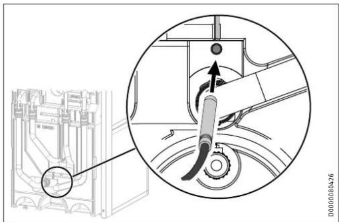
text_image
Technical diagram showing mechanical assembly with a magnified inset highlighting a component detail and directional arrow.natural_image
Technical diagram showing a mechanical assembly with a magnified inset view of a component (no text or symbols present)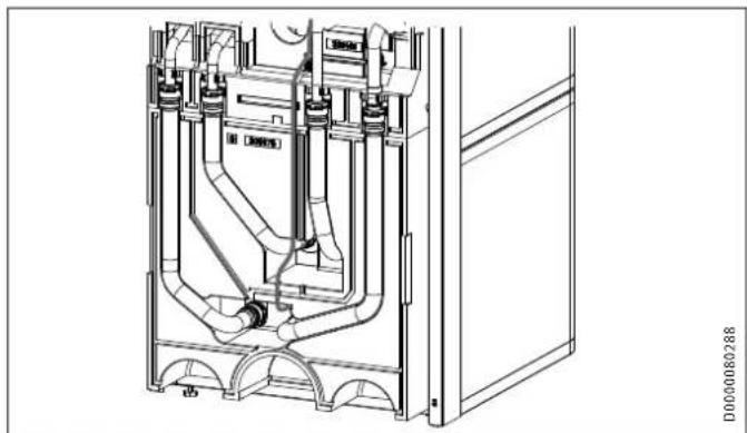
natural_image
Technical line drawing of a mechanical or electrical component with pipes and housing (no text or symbols)ITALANO
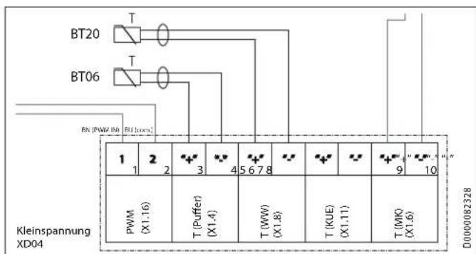
text_image
BT20 BT06 RN (PWM IN) RN (Iors): 1 2 3 4 5 6 7 8 9 10 PWM (X1.16) T (Puffer) (X1.4) T (WW) (X1.8) T (KUE) (X1.11) T (WK) (X1.6) D0000082328 Kleinspannung XD04text_image
Diagram showing various icons and symbols with labels like '3‰' and '10‰', likely representing technical or operational components.natural_image
Technical line drawing of a mechanical assembly with an inset close-up showing internal components (no text or symbols)natural_image
Technical line drawing of a dual air conditioning unit with fan and cooling unit (no text or symbols)D0000080569
HSBC 300 L cool

natural_image
Technical line drawing of a dual-chamber industrial system with pipes and control panels (no text or symbols)D0000080571D0000080570

natural_image
Pure technical line drawing of two vertical rectangular units connected by pipes, no text or symbols presentPlant C3, XEDA International Industry City
Xiqing Economic Development Area
300085 Tianjin
Tel. 022 8396 2077 | Fax 022 8396 2075
info@stiebeleltron.cn
www.stiebeleltron.cn
Czech Republic
STIEBEL ELTRON spol. s r.o.
K Hájüm 946 | 155 00 Praha 5 - Stodülky
Tel. 251116-111 | Fax 235512-122
Urzhumskaya street 4,
building 2 | 129343 Moscow
Tel. 0495 7753889 | Fax 0495 7753887
info@stiebel-eltron.ru
www.stiebel-eltron.ru
Slovakia
TATRAMAT - ohrievače vody s.r.o.
Hlavná 1 | 058 01 Poprad
Tel. 052 7127-125 | Fax 052 7127-148
info@stiebel-eltron.sk
www.stiebel-eltron.sk
Switzerland
STIEBEL ELTRON AG
Industrie West
Gass 8 | 5242 Lupfig
Tel. 056 4640-500 | Fax 056 4640-501
info@stiebel-eltron.ch
www.stiebel-eltron.ch
Thailand
STIEBEL ELTRON Asia Ltd.
469 Moo 2 Tambol Klong-Jik
Amphur Bangpa-In | 13160 Ayutthaya
Tel. 035 220088|Fax 035 221188
info@stiebeleltronasia.com
www.stiebeleltronasia.com
United Kingdom and Ireland
STIEBEL ELTRON UK Ltd.
Unit 12 Stadium Court
Stadium Road | CH62 3RP Bromborough
Tel. 0151 346-2300 | Fax 0151 334-2913
info@stiebel-eltron.co.uk
www.stiebel-eltron.co.uk
United States of America
STIEBEL ELTRON, Inc.
17 West Street | 01088 West Hatfield MA
Tel. 0413 247-3380 | Fax 0413 247-3369
info@stiebel-eltron-usa.com
www.stiebel-eltron-usa.com

text_image
4017213336860Irrtum und technische Änderungen vorbehalten! | Subject to errors and technical changes! | Sous réserve d'erreurs et de modifications techniques! | Onder voorbehoud van vergissingen en technische wijzigingen! | Salvo error o modificación técnica! | Excepto erro ou alteração técnica | Zastrzeżone zmiany techniczne i ewentualne błędy | Omyly a technické zmény jsou vyhrazeny! | A muszaki változtalások és têvedések jogát fenntartjuk! | Otcytствие ошибok ne гарантируется. Возможны технические изменения. | Chyby a technické zmény sű vyhradené! Stand 9442
STIEBEL ELTRON