
CPPS32084 - Laboratory power supply VOLTCRAFT - Free user manual and instructions
Find the device manual for free CPPS32084 VOLTCRAFT in PDF.

| Brand | VOLTCRAFT |
| Model | CPPS32084 (CPPS-320-84) |
| Product type | Laboratory switching power supply |
| Input voltage | 100 - 240 V AC, 45 - 65 Hz |
| Max input current | < 1.8 A (at 230 V AC) |
| Output voltage | 0 - 84 V DC, continuously adjustable |
| Output current | 0 - 10 A, continuously adjustable |
| Max output power | 320 W |
| Voltage regulation (load variation 10-100%) | ≤ 80 mV |
| Current regulation (load variation 10-90%) | ≤ 50 mA |
| Display accuracy | ±(0.2% + 5 digits) for V and A |
| Efficiency | 85% (typical) |
| Power factor (active PFC) | ≥ 0.9 |
| Integrated protections | Overvoltage (OVP), overtemperature (OTP), overload (OLP), short-circuit protection |
| Special functions | PRESET presets (3 memories), V/t function, A/B/C curve generator, remote control (external voltage or potentiometer), USB/PC control, Sense function |
| Display | Digital display with C.V. (constant voltage) and C.C. (constant current) indicators |
| Connections | 4mm safety output terminals (red/black/green), USB port, 5-pin remote control terminal, Sense terminals |
| Cooling | Temperature-controlled fan (0-100%) |
| Dimensions (W × H × D) | 200 × 95 × 245 mm |
| Weight | 2.3 kg |
| Operating temperature | 0 °C to +40 °C |
| Operating humidity | 10% to 80% RH (non-condensing) |
| Protection class | I (with grounding) |
| Standards | CE, EN 55012, EN 61010 |
| Maintenance | Clean with dry antistatic cloth; replace mains fuse (T3.15AL250V, 5x20 mm) |
| Package contents | Device, power cord, USB cable, software CD, remote connector, instruction manual |
Frequently Asked Questions - CPPS32084 VOLTCRAFT
Caution: Fuses are not covered by the warranty.
User questions about CPPS32084 VOLTCRAFT
0 question about this device. Answer the ones you know or ask your own.
Ask a new question about this device
Download the instructions for your Laboratory power supply in PDF format for free! Find your manual CPPS32084 - VOLTCRAFT and take your electronic device back in hand. On this page are published all the documents necessary for the use of your device. CPPS32084 by VOLTCRAFT.
USER MANUAL CPPS32084 VOLTCRAFT
www.business.conrad.at
External Timed Program
Data Log
Setting


Setting Func A,B,C
| A | B | C | |
| Voltage(V) | 0 | 0 | 3 |
| Current(A) | 5 | 7 | 9 |
| Time(S) | 2 | 1 | 3 |
ABCRecalls
| C A C B C C |
| Apply |
Setting Transit Time
| A-B | B-A | A-C | C-A | B-C | C-B |
| 0 | 0 | 2 | 2 | 2 | 2 |
Run
| B-A | Run |
WaveForm Preview set
External Timed Program
Data Log


Setting Func.A,B,C
| A | B | C | |
| Voltage(V) | 5 | 10 | 3 |
| Current(A) | 5 | 7 | 9 |
| Time(S) | 3 | 3 | 3 |
ABCRecalls
| C A C B C |
| Apply |
Setting Transit Time
| A·B | B·A | A·C | C·A | B·C | C·B |
| 3 | 3 | 4 | 0 | 3 | 0 |
Run
| A-B | Run |
Wave Form Preview set
a) Persons / Product 41
b) Miscellaneous. 42
- Operating elements 43
- Operation 44
a) Connecting the power cable 44
b) Setting up the device 44
c) General information 44
- Normal operation 46
a) Set current limit. 46
b) Set output voltage. 46
c) Connecting a consumer. 47
- Function buttons 48
a) Key lock function 48
b) Manual output ON/OFF 48
c) Adjustable ammeter / watt-meter. 48
- "PRESET" memory location operation 49
- V / t Function 50
a) Presetting the DC voltage source. 50
b) Setting the V / value 50
- A/B/C function and curve generator 52
- Remote control 54
a) Preparing the remote control connection. 54
b) Control via the external voltage source 55
c) Control via controllable resistance (potentiometer) 56
d) Output remote control (on/off) 56
- Resetting the factory settings 57
- Sense function 58
- Software installation 59
page
- Control with pc software 59
External timed program 63
- Protective measures 64
a) Over-voltage protection 64
b)Overheating protection 64
c) Overload protection 64
- Maintenance and cleaning 65
a) General 65
b) Exchanging the fuse 65
-
Troubleshooting 66
-
Declaration of conformity (DOC) 67
- Disposal 67
- Technical data 68
1. INTRODUCTION
Dear customer,
In purchasing this Voltcraft® product, you have made a very good decision for which we would like to thank you.
Voltcraft - In the field of measuring, charging and network technology, this name stands for high-quality products which perform superbly and which are created by experts whose concern is continuous innovation.
From the ambitious hobby electronics enthusiast to the professional user, products from the Voltcraft® brand family provide the optimum solution even for the most demanding tasks. And the remarkable feature is: we offer you the mature technology and reliable quality of our Voltcraft® products at an almost unbeatable price-performance ratio. In this way, we aim to establish a long, fruitful and successful co-operation with our customers.
We wish you a great deal of enjoyment with your new Voltcraft® product!
All names of companies and products are trademarks of the respective owner. All rights reserved.
If there are any technical questions, please contact:
International: www.conrad.com/contact
United Kingdom: www.conrad-electronic.co.uk/contact
2. INTENDED USE
The laboratory power supply serves as DC voltage source to operate low voltage consumers. The adjustable output on the front side can be loaded up to the full nominal current. The output is protected against overload. Hazardous contact voltages >75V / DC can be generated with the series connection of outputs of several power supplies. Insulated wires/measurement lines must be used for safety reasons from this voltage. This applies accordingly when using a single power supply unit with order number 1367576, since this provides an output voltage of up to 84 V/DC. The connection is made via 4 mm safety sockets.

Sufficiently dimensioned connection cables must be used. Too smaller conductor cross section can lead to overheating and fire.
The output data of the laboratory power supplies is as follows:
| Type Output voltage Output current | |
| CPPS-320-42 0 - 42 V/DC 0 - 20 A | |
| CPPS-320-84 0 - 84 V/DC 0 - 10 A |
The voltage and current is set continuously via digital rotary knobs with rough and fine adjustment to enable fast and precise value setting. The values are displayed in the clear display.
The power supply is remote controlled. The output voltage and the output current can be set via an external voltage (0 - 5 V/DC) or an external potentiometer (5 kOhm). The DC output is switched on and off via a switching contact.
Three freely programmed storage spaces can be allocated with different fixed voltages and current limits.
The power supply can be controlled to operate cyclical work flows via a PC with the software and USB connection included in the delivery scope. Up to 20 programmable voltage and current sets with different periods can be programmed for operation. The cyclical work flows can be repeated up to 999 times.
The device is overload and short circuit proof and includes a safety and temperature shutdown. The laboratory power supply is set up in protection class I. It should only be connected to the protective contact sockets with protective earthing and a household AC voltage of 100 - 240 V/AC.
For safety and approval purposes (CE), you must not rebuild and/or modify this product. If you use the product for purposes other than those described above, the product may be damaged. In addition, improper use can cause hazards such as short circuiting, fire, electric shock etc. Read the instructions carefully and keep them. Make this product available to third parties only together with its operating instructions.
This product complies with the statutory national and European requirements.
3. DELIVERY CONTENT
Laboratory power supply
Power cable
USB cable
- Software CD
- Plug for remote connection
- Operating instructions
4. SYMBOL EXPLANATION

This symbol indicates health risks e.g. due to electric shock.

The symbol with an exclamation mark in a triangle indicates important instructions contained in these operating instructions that must be followed.

The arrow symbol alerts the user to the presence of important tips and notes on using the device.

Only use indoors in dry locations.

This device is CE-compliant and complies with all national and European legal requirements.

Protective ground wire connection; do not loosen this screw.
Read the operating instructions carefully and especially observe the safety information. If you do not follow the safety instructions and information on proper handling in these operating instructions, we assume no liability for any resulting personal injury or damage to property. Such cases will invalidate the warranty/guarantee.
a) Persons / Product
- The device is not a toy. Keep it out of the reach of children and pets.
- Do not leave packaging material lying around carelessly. These may become dangerous playing material for children.
- Protect the product from extreme temperatures, direct sunlight, strong jolts, high humidity, moisture, flammable gases, vapours and solvents.
- Do not place the product under any mechanical stress.
-
If it is no longer possible to operate the product safely, take it out of operation and protect it from any accidental use. Safe operation can no longer be guaranteed if the product:
-
is visibly damaged,
- is no longer working properly,
- has been stored for extended periods in poor ambient conditions or
-
has been subjected to any serious transport-related stresses.
-
Please handle the product carefully. Jolts, impacts or a fall even from a low height can damage the product.
- Also observe the safety and operating instructions of any other devices which are connected to the product.
- Products which are operated at the power supply should be kept out of reach of children.
- Therefore, while using the product be especially careful when children are around. They could try to insert objects into the device through the openings in the housing. There is a danger of a life threatening electric shock!
- Never pour liquids over electrical devices and never place objects filled with liquid on top (e.g. glasses) or near to devices. This poses a great fire hazard and risk of electric shock.
- Only operate the product in dry interiors. It may not become moist or wet. This poses a risk of fatal electric shock!
- The use of electrical devices must be supervised by trained staff in schools, training centers, hobby and do-it-yourself workshops.
- In industrial facilities, heed all applicable accident prevention regulations for electrical installations and equipment.
- Voltage carrying parts can be exposed when opening covers or removing parts. Therefore disconnect the product from all voltage sources before maintenance or repairs. Capacitors inside the device can be live even after the device has been disconnected from all power sources.

Always lay the cables so that nobody can trip over or become entangled in them. This poses a risk of injury.
- Do not wear any metal or conductive necklaces, bracelets, rings etc when working with power supplies. Under no circumstances connect the power supplies and chargers to persons or animals.
- Check the product for damage before each use. In case of obvious damage, do not use the product anymore. Disconnect the mains voltage and unplug the mains plug from the mains socket. Then have the product checked by a specialist shop.
Only use a correct power plug (100 - 240 V/AC, 50/60 Hz) of the public power supply as voltage source.
-
The mains outlet must be located near to the device and be easily accessible.
-
Do not touch the mains cable if it is damaged. First, power down the respective mains socket (e.g. via the respective circuit breaker) and then carefully pull the mains plug from the mains socket. Never use the product if the mains cable is damaged.
- Replace a damaged mains cable with a structurally identical new mains cable.
-
Do not remove the mains plug from the mains socket by pulling on the cable!
-
Unplug the product under the following conditions:
-
before cleaning the product
- in case of a storm
-
for extended periods of disuse.
-
Please ensure adequate ventilation of the product during operation. Do not cover the ventilation openings with magazines, covers, curtains. Maintain a minimum distance of 15cm from the other objects.
When setting up the product, make sure that the cable is not pinched, kinked or damaged by sharp edges
Devices with strong electrical or magnetic fields such as transformers, motors, cordless telephones, radios etc should not be placed near the product, since these could affect the product.
- Do not operate the product in areas or rooms with unfavorable ambient conditions. This can damage the sensitive electronics inside the product and is a threat to life. Adverse ambient conditions are defined as such:
- High humidity (>80%) relative, condensation)
- Humidity, dust, flammable gas, solvent vapors, petrol.
-
High ambient temperature (> approx. +50 °C)
-
Electromagnetic fields (motors, transformers etc.) or electromagnetic fields
-
Do not attach the device just after moving it from a cold to a warm space. When this happens, condensation may form which can cause damage to the device. Wait until the product has adjusted to the ambient temperature.
b) Miscellaneous
- Consult a professional if you require assistance with product operation, safety or connection.
- Maintenance work, adjustments and repairs may be carried out only by a professional or at a specialist workshop.
- If you have questions which remain unanswered by these operating instructions, contact our technical support service or other technical personnel.
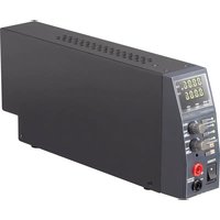
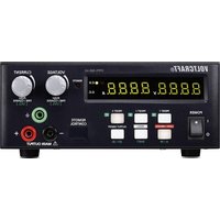
6. OPERATING ELEMENTS
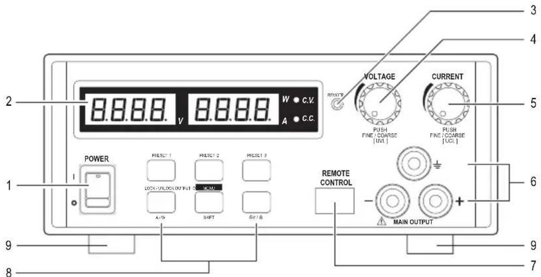
1 On/off switch POWER
2 Measuring display element with indicator for C.V. (Constant voltage) and C.C. (Constant current)
3 LED remote control display (remote control/USB mode)
4 Adjusting controller VOLTAGE (output voltage)
5 Adjusting controller CURRENT (output voltage)
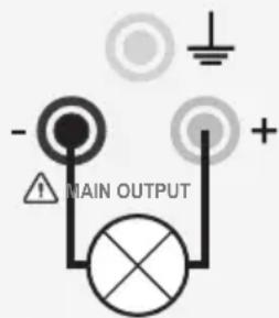
6 Connector sockets MAIN OUTPUT (max. 20 A by CPPS-320-42, max. 10 A by CPPS-320-84)
7 USB-connector
(for connecting to a computer, for cyclical operation with programmed voltage, current, time and time cycle)
8 Illuminated function buttons (PRESET 1, 2, 3 buttons, LOCK/UNLOCK button (A/W measurement button), MENU button (SHIFT button), OUTPUT ON/OFF button ( V / t button))
9 Folding feet
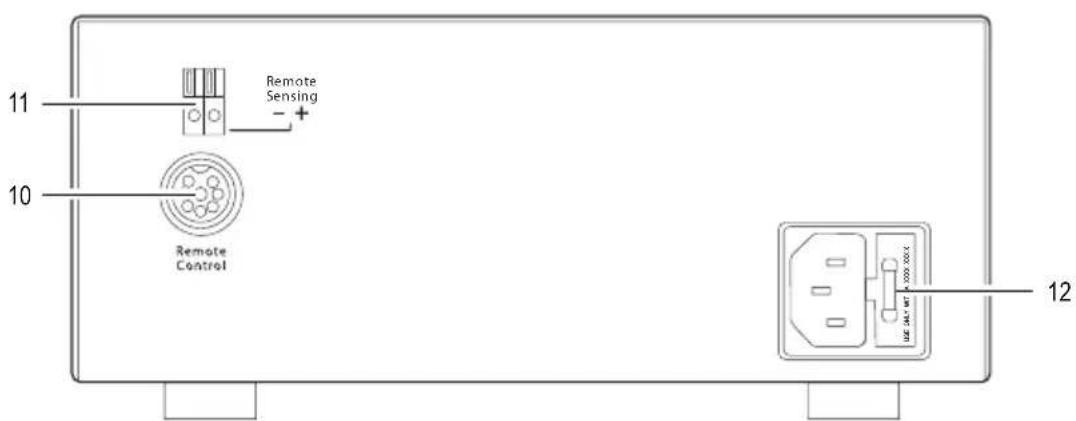
10 Remote control connection Remote Control
11 Connector sockets Remote Sensing
12 Cold device connection and mains fuse

The laboratory network device is not a charger. Use a suitable charger with corresponding charging shutdown to charge batteries.
The housing surface heats up during longer operation with nominal load. Caution! Possible danger of burning. Therefore please ensure adequate ventilation of the power supply and never operate it partially or wholly covered, to avoid possible damage.
When connecting a consumer please ensure that it is switched off. A switched on consumer can cause sparks when connecting it to the output sockets of the power supply which can damage the sockets or the connected lines and/or terminals of these.
If you do not need your power supply, switch it off and disconnect it from the network. The displays stay on for a few seconds after switch off to discharge the internal condensators and save the parameters last set. Please ensure a sufficient conductor cross section of the DC connection lines since an overload can lead to cable fire.
a) Connecting the power cable
- Connect the protective contact power cable provided to the cold device connection (12) at the power supply. Please ensure a secure fit.
- Connect the power cable to a protective contact socket. The total length of the power cable to the socket should not exceed 3m
b) Setting up the device
Place the laboratory network device onto a stable, level and insensitive surface. Please ensure that the ventilation slits in the housing are not covered.
c) General information
The laboratory network device is controlled by microprocessors and is operated via two digital setting controllers (incremental encoders without end position) with button function. This enables the fine and rough control via a controller.
A system check takes place after switch on. The test status is displayed on both displays. The display sequence is as follows:

Display the current software status.
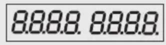
Segment test whether the display functions with all individual segments. Switch over to the normal operational display after this step.
The power supply enables operation in three modes. The following modes are possible:
| Normal Normal operation: The voltage and current are set at the front. | |
| Preset | Storage space operation: Three fixed voltages can be saved and directly selected via this preset function. The selection is made via the PRESET 1, 2, 3 selection buttons (8) and the settings via the (4, 5) setting controller. |
| Remote Ctrl | Remote control. The power supply can be remote controlled via an external voltage or an external potentiometer. The voltage and current can be remote controlled. The front setting controllers are inactive however, can be activated or deactivated again via the LOCK/UNLOCK (8) button. |
The individual operating modes will be described in detail in the following chapters.
8. NORMAL OPERATION
The power supply can be operated via the front setting controller in normal operation. Remove the connected consumer from the output (6).
Switch on the power supply via the POWER (1) on/off switch.
The display (2) lights up and the voltage and current display appears after a short self-test.

First set the current limit before each voltage setting. Your connecting cables can be damaged by a high current value. The output voltage can be limited by a low current value (<1A).
a) Set current limit
A protective mechanism limits the output current to protect the consumer or the connecting cables. The current limitation can be preset without short circuiting at the output. The power supply then delivers the maximum preset current.
- Remove the connected consumer from the power supply.
- Switch on the power supply POWER on/off switch (1). The display (2) lights up and after a short self test the voltage and current display appears.
- Set the current limiter on the CURRENT setting controller (5) according to your needs.
- Turn the controller and the current limitation value appears.

The display switches back to the current power display if a setting is not made within 2 seconds.
- Turn the setting controller to the left or right to set the current limitation. This is represented by a slightly lighter digit. Briefly press the setting controller. The decimal point (1.0 or 0.1) of the setting range changes each time the button is pressed. Turning changes the value.
- The setting can be made roughly (in the unit range) or precisely (in the one tenth range).
- The display automatically switches back to normal display after approximately 2 seconds if the desired current value was set.

The power supply switches to current limitation mode and also reduces the voltage value if the preset current strength is reached in normal operation. This operation is signaled with the red C.C. status display (2).
b) Set output voltage
The output voltage can be set at the VOLTAGE (4) setting control. The rough and fine control is carried out in the same way as the setting of the current limitation.

It could be that the voltage setting requires approx. 1-2 seconds to adjust from a high to a low voltage value through the large control range.

The device works in constant voltage mode during normal operation. This means that the power supply delivers a constant preset output voltage. This mode is signaled with the green C.V. status display (2).
c) Connecting a consumer

When connecting a consumer to the power supply please ensure that it is switched off. The maximum power consumption of the connected consumer should not exceed the specifications in the technical data.
Dangerous contact voltages ( >75V / DC ) can be generated with the series connection of outputs of several power supplies, which could be a risk to life when touching. Only insulated accessories (connection cables, measuring lines etc.) may be used from this voltage. This applies accordingly when using a single power supply unit with order number 1367576, since this provides an output voltage of up to 84V / DC . The use of metallic cables and contacts should be avoided. All these blank points should be covered with suitable, flame resistant insulating material or other measures and protected from direct contact and short circuits.
Please ensure a sufficient conductor cross section for the intended current strength.
- Remove the connected consumer from the output.
- Switch on the power supply via On / off switch POWER (1) The display (2) lights up and the voltage and current indicator appears in the display.
- Set the parameters according to your guidelines as described in the chapter "Start up". Check the correctly set output voltage once more.
- Connect the positive pole (+) of the consumer to the red socket "+" and the negative pole (-) to the black socket "- of the output.

The green jack provides the earthing connection
- The connected consumer can now be switched on.

The current consumption of the connected consumer is indicated in the display (2) in ampere (A).
9. FUNCTION BUTTONS
The illuminated function buttons (8) can be used in different ways and combinations.
a) Key lock function
- Press the LOCK/UNLOCK button, to block or unblock all function buttons / control dials on the front of the device.
- The LOCK/UNLOCK button lights up if all function buttons / control dials on the front of the device are blocked.
b) Manual output ON/OFF
- Press the OUTPUT ON/OFF button to manually switch the output on /off.
- The OUTPUT ON/OFF button lights up if the output is switched on.
c) Adjustable ammeter / watt-meter
- Press the SHIFT button and then the LOCK/UNLOCK button, to change from the ammeter to the watt-meter.
- Press the SHIFT button again and then the LOCK/UNLOCK button when wanting to change back to the ammeter.
10. “PRESET” MEMORY LOCATION OPERATION
Three fixed voltages including the current settings can be directly selected via the preset function in the device. All three memory locations (PRESET 1, 2, 3) are preset by the factory.
| Memory Type | PRESET 1 PRESET 2 PRESET 3 | |||||
| Voltage Current | Voltage Current | Voltage Current | ||||
| CPPS-320-42 5 V | Maximum 13.8 V | Maximum 20 V | Maximum | |||
| CPPS-320-84 5 V | Maximum 13.8 V | Maximum 20 V | Maximum | |||

Please ensure that no consumers are connected.
The data memory can be set via the software provided. Please also note the chapter "Control with PC software".
- Press any selection button PRESET 1, 2, 3 (8). The button lights up and the preset values are indicated in the display (2).
- You can change the preset voltage and current values according to your needs. The output voltage can be changed at the VOLTAGE setting controller (4) and the output current at the CURRENT (5) setting controller.

If you change the preset voltage and current values, these values are stored, if the laboratory power supply is switched off. Always test the values set before connecting a consumer.
-
Press the SHIFT (8) button and then any selection button PRESET 1, 2, 3 (8). To test the preset values. The preset values are indicated in the display (2). The display switches back to normal display after approximately 2 seconds.
Read the chapter "Resetting the values set" to reset the values set to the factory settings. -
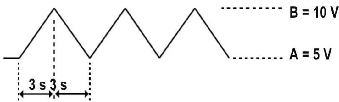
V a-b shows the voltage range of level A to level B.
- t a-b shows the time in seconds from level A to level B. The running time can be set from 0 to 20 seconds.
a) Presetting the DC voltage source
There are in total three voltage sources which can be preset. They are labeled with A, B and C.
- Press the PRESET 1, 2, 3 (8) selection button. The corresponding button lights up.
- Set the desired voltage value with the setting controller VOLTAGE (4).
- Press the corresponding PRESET button to leave the setting mode. The button is no longer illuminated.
b) Setting the V / value
- Press and hold the MENU (8) button for approximately 3 seconds.
- Turn the VOLTAGE (4) setting controller until the following display appears:

- Then press the VOLTAGE (4) setting controller to reach the setting mode.
- Turn the VOLTAGE (4) setting controller until the following display appears

- Turn the setting controller VOLTAGE (4), to select the desired voltage range, the transit time of which you want to set.
The sequence of the different voltage ranges reads as follows:
AB BA AC CA BC CB
- Turn the CURRENT (5) setting controller, to set the transit time, when you have selected the desired voltage range.
For example:
You want to set the transit time between the voltage sources A and B.
- Press and hold the MENU (8) button for approximately 3 seconds.
- Turn the setting controller VOLTAGE (4) until the following display appears:

- Then press the setting controller VOLTAGE (4) to reach the setting mode.
- Turn the setting controller VOLTAGE (4) until the following display appears:

- Turn the setting controller CURRENT (5) until the following display appears:

- Press the setting controller VOLTAGE (4), to confirm the selection.
- The transit time between the voltage source A and B now amount to 5 seconds.
- Repeat the steps 1 to 4 for the other voltage ranges.
Transit times of 0 to 20 seconds can be set.
12. A/B/C FUNCTION AND CURVE GENERATOR
The A/B/C function determines the duration (0 to 600 seconds) for which the respective voltage source A/B/C remains active before it moves to the next voltage source.
Before setting the A/B/C function first enter the V / t value (→ chapter 11 b).
- Press and hold the MENU (8) button for approx. 3 seconds.
- Turn the setting controller VOLTAGE (4) until the following display appears:

- Then press the setting controller VOLTAGE (4) to reach the setting mode.
- Select the function A, B or C and turn the setting controller CURRENT (5) to set the time period (0 to 600 seconds).
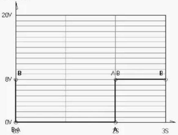
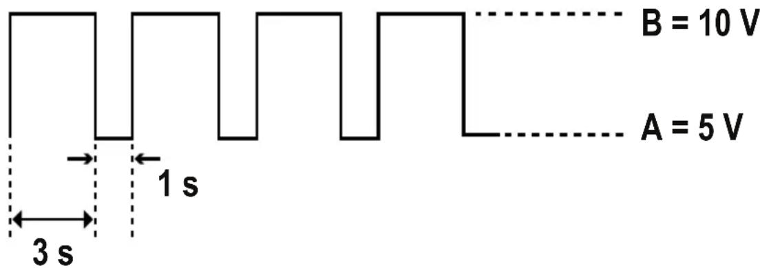
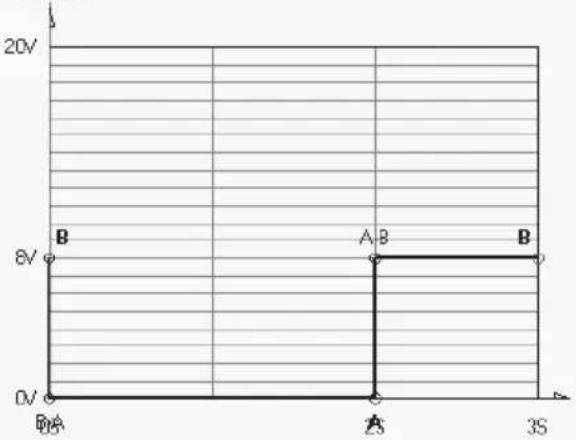
Example 1:
Pulse waveform with 3 seconds at 10V and 1 second at 5V
A (PRESET 1) = 5 V
B (PRESET 2) = 10 V
- FUNC A = 1 second
- FUNC B = 3 seconds
- t a - b = 0
- t b - a = 0
- To generate the waveform, press the SHIFT (8) button, then the V / t (8) button.
- The waveform will be periodically generated.
- To stop generating the waveform press SHIFT (8) button, then the V / t (8) button.
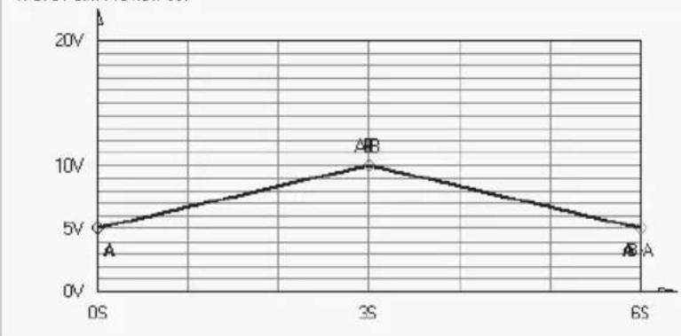
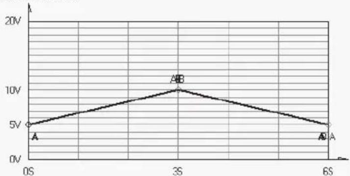
Example 2:
- Triangle waveform
A (PRESET 1) = 5 V
B (PRESET 2) = 10 V - t a-b = 3 seconds
- t b-a = 3 seconds
- FUNC A = 3 seconds
-
FUNC B = 3 seconds
-
To generate the waveform, press the SHIFT (8) button, then the V / t (8) button.
- The waveform will be periodically generated.
- To stop generating the waveform press SHIFT (8) button, then the V / t (8) button.
13. REMOTE CONTROL
The voltage and current can be set with an external voltage source or an external, adjustable resistance (abbreviation "Poti") via the installed remote control connection Remote Control (10). The remote control is connected to the rear remote control connection Remote Control (10). A plug for the remote connection is enclosed for the connection.

The current control bus must always be connected in the remote control since otherwise the output switches to the current limitation mode "C.C." and limits the output voltage.
a) Preparing the remote control connection
- Loosen the side screws of the remote connection socket and remove the front, black contact socket with a small turning movement.
- Insert five connection lines with a cable cross section of at least 0.34mm^2 from behind through the metal sleeves. Carefully solder these cables to the solder tails no. 1, 2, 3, 4 and 5 of the black contact sockets. Please ensure there are no short circuits.

The digits of the soldering lugs are specified on the black insulator.
Mark the loose cable ends with the corresponding contact digits (1-5) to rule out confusion.
Place the black contact sockets in reverse order into the metal sleeves and carefully screw these together.
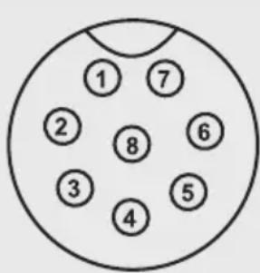
The pin connections read as follows:
Contact 1 Internal control voltage +5V / DC (< 50~mA)
Contact 2 Voltage setting
Contact 3 Current setting
Contact 4 Ground potential (_n Ground
Contact 5 On/off output
Contact 6 - 8 Not allocated
- Switch off the power supply and then connect the remote socket to the rear remote control socket Remote Control (10). Screw together the external fastening ring.
- Control the voltage of the external voltage source at 0V
- Switch on the power supply.
- Hold the MENU (8) button for approx. 3 seconds.
- Turn the setting controller VOLTAGE (4) until the following display appears:

- Then press the setting controller VOLTAGE (4) to reach the setting mode.
- Turn the setting controller CURRENT (4) to switch the remote control on or off. ON or OFF appears in the right display.
- Press the MENU (8) button to confirm the selection and leave the setting mode.

All illuminated function buttons (8) determined after the remote control mode was activated. The LOCK/UNLOCK (8) button and the LED remote control display (3) light up.
- To deactivate the remote control mode press the LOCK/UNLOCK (8) button, to activate all function buttons (8).
- Repeat steps 4 to 8.
b) Control via the external voltage source
The power supply can be remote controlled with an external voltage source of 0 to 5 V/DC over the entire range for voltage and current.
Connect the connection lines to the remote sockets as illustrated.
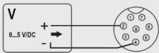
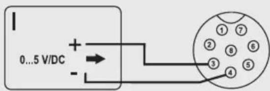
Voltage setting "V" Current setting "I":
- Connection 2 to the positive pole (+) of the external control voltage.
-
Connection 4 to the negative pole (-) of the external voltage source.
-
Connection 3 to the positive pole (+) of the external control voltage
- Connection 4 to the negative pole (-) of the external voltage source

The voltage at the remote control connection should not exceed 5 V/DC. The connections should not be short circuited.
c) Control via controllable resistance (potentiometer)
The power supply can be remote controlled with an external potentiometer (5 kOhm) over the entire range for voltage and current.
Connect the connection lines to the remote sockets as illustrated.
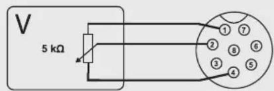
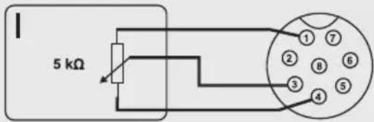
Voltage setting "V" Current setting "I":
- Connection 1 at one end of the resistor. - Connection 1
at the end of the resistor.
-
Connection 2 at the middle sliding contact of the resistor.
-
Connection 3 at the middle sliding contact of the resistor.
-
Connection 4 at the second end of the resistor. - Conne
action 4 at the second end of the resistor.

The connections 1 and 4 should not be short circuited.
d) Output remote control (on/off)
The DC output can be switched on and off via a switch contact. Proceed as follows for the connection:
- Connect the connection lines to the remote sockets as illustrated.
- Connect the 4 and 5 connection to a potential free switch contact.
- The status displays C.V. and C.C. flash when the output is switched off. In addition the display (2) indicates the current settings of the output voltage and output current.
- You can determine the output values with the setting controller for voltage VOLTAGE (4) and current limitation CURRENT (5) when the output is switched off.
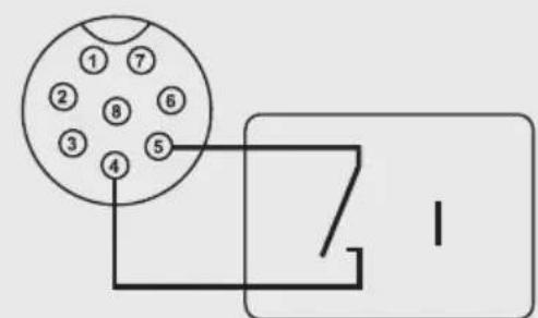
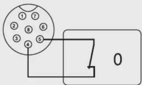

No voltage should be applied t contacts 4 and 5.
14. RESETTING THE FACTORY SETTINGS
- Hold the MENU (8) button for approximately 3 seconds.
- Turn the setting controller VOLTAGE (4) until the following display appears

- Then press the setting controller VOLTAGE (4) to reach the setting mode.
- Turn the CURRENT (5) setting controller. "Yes" or "No" appears in the right display.
- Select "Yes" and then press the setting controller VOLTAGE (4) to confirm the selection and return to the setting mode.
- Then press the MENU (8) button, to leave the setting mode The laboratory network device starts again with the values set by the factory.
15. SENSE FUNCTION
The sense function is an automatic voltage control for the connection sockets MAIN OUTPUT (6).
In addition two separate measurement lines are connected parallel to the connection lines. The voltage drop, which occurs at the connection lines, is measured on both these measurement lines. This voltage drop automatically balances the laboratory power supply so that the voltage actually set fits the consumer.
Switch off the power supply and consumer.
Always first connect the power supply lines of the power supply to the consumer. Please note the correct polarity.
Press the terminal release inside with a small screw driver on the rear connection sockets Remote Sensing (11) and stick the cables into the clamp openings. Check the secure position.
Now connect both sense lines to the consumer at the correct polarity. The conductor cross section for the sense lines must always amount to at least 0.34mm^2
Always loosen the connections in reverse order (first the sense lines and then the connection lines).
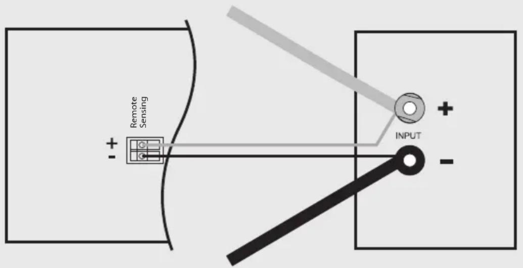

Please ensure that the sense cables are connected as near as possible to the connection point of the consumer. Please note the correct polarity.
Never short circuit the sense lines.
16. SOFTWARE INSTALLATION

The software is compatible with Windows XP, Vista 7, 8 operating systems.
- Insert the supplied CD with the software into the corresponding drive of your computer.
- Install the software while double clicking on "setup.exe".
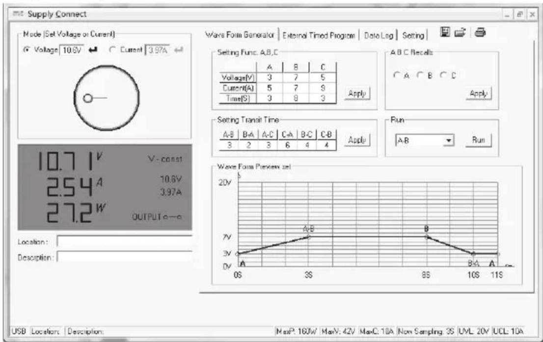
17. CONTROL WITH PC SOFTWARE
- Connect the power supply to a free USB interface of your PC using the USB cable. Connect the USB cable supplied to the USB socket (7).
- Switch on the power supply.
- Start the program. After launching the software, the power supply unit is controlled via the software.

The product reacts no more to entries through the control buttons on the front of the device.
- After starting the software, the following window appears:
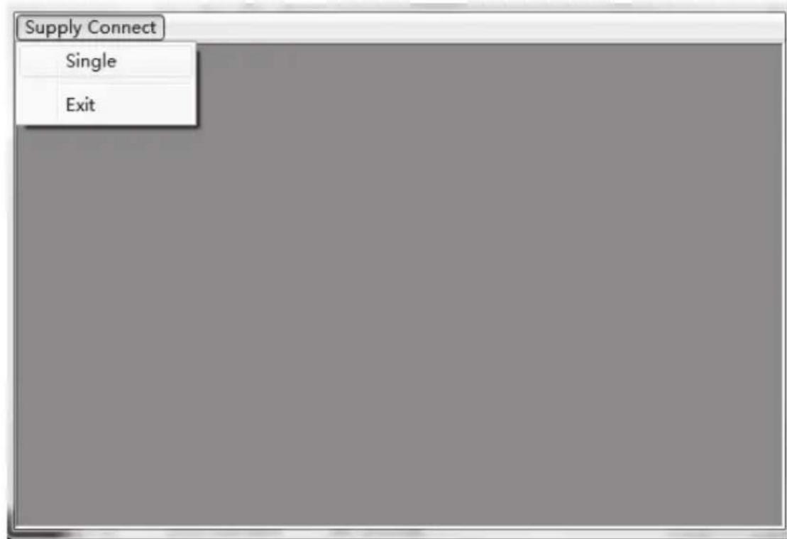
- Click with the left mouse button on "Supply Connect" and then "Single". The following window appears:
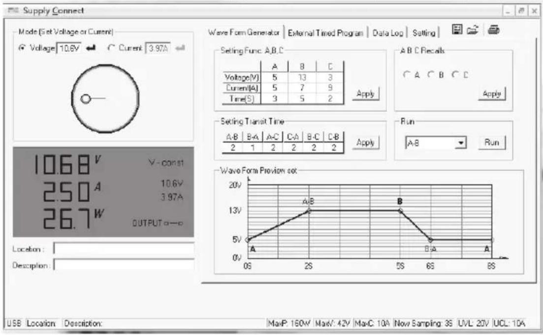
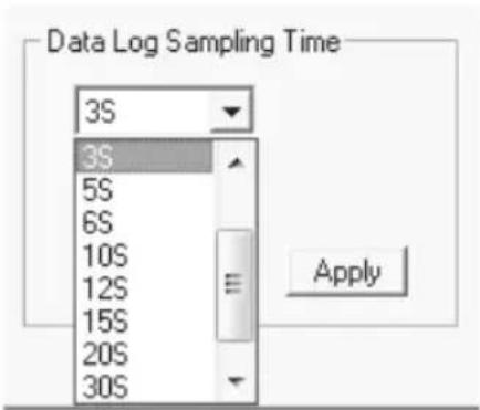
- Click on "Setting". The following view appears:
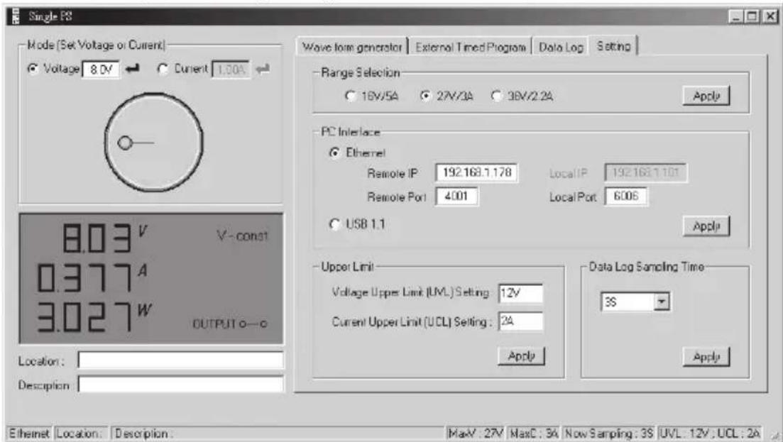
- Set the V/I range. In the following drop down menu the datalogger sampling rate can be selected.
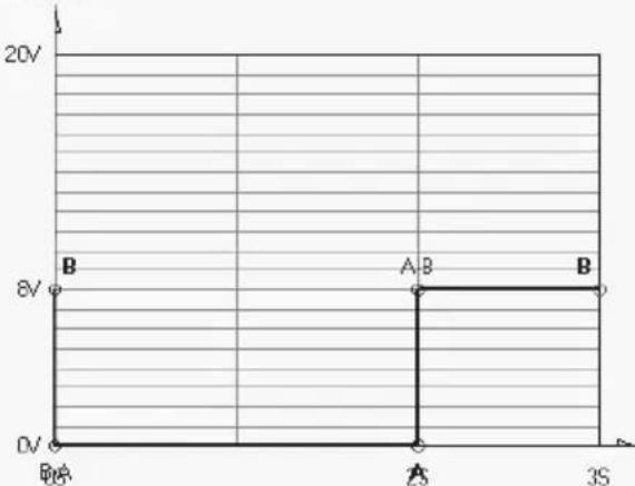
Example 1 of the preview of the waveform:
Wave Form Generator
External Timed Program DataLog Setting


-SettingFunc.A.B.C
| A | B | C | |
| Voltage(V) | 0 | 8 | 3 |
| Current(A) | 5 | 7 | 9 |
| Time(S) | 2 | 1 | 3 |
| ABCRecalls |
| CA B C |
| Apply |
Setting Transit Time
| A-B | B-A | A-C | C-A | B-C | C-B |
| 0 | 0 | 2 | 2 | 2 | 2 |
| B-Δ | Run |
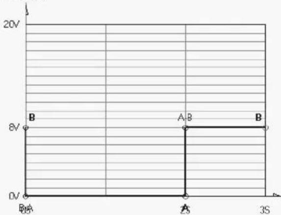
WaveForm Preview set
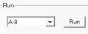
Example 2 of the preview of the waveform:
Wave Form Generator
External Timed Program Data Log Setting


Setting Func.A,B,C
| A | B | C | |
| Voltage(V) | 5 | 10 | 3 |
| Current(A) | 5 | 7 | 9 |
| Time(S) | 3 | 3 | 3 |
| ABC Recalls |
| CA CB CC |
| Apply |
Setting Transit Time
| A·B | B·A | A·C | C·A | B·C | C·B |
| 3 | 3 | 4 | 0 | 3 | 0 |
| Run | |
| A-B | Run |
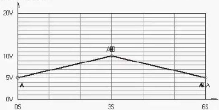
WaveForm Preview set
Example 3 of the preview of the waveform:
External timed program
The unit can be externally programmed via a computer to run 20 steps, each with a preset voltage, current limiting value and a preset time period of 1 second to 99 minutes. The timed program can be set to run from one cycle to infinite cycles.
Window for externally timed programming
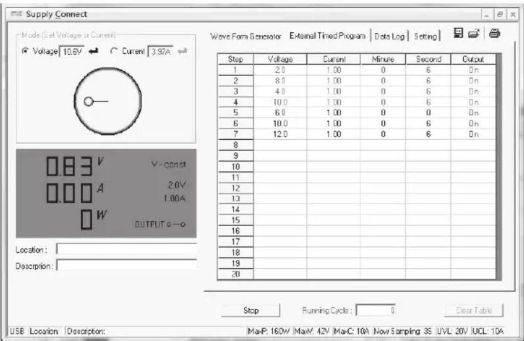
Clear Table: Delete all data in the table
Run (Stop): Run or stop the timed program
Running Cycle: The number of cycles of 0 - enter 9999. 0 = infinite
Output ON / OFF: ON = output for this step is switched on / OFF = off
Procedure
- Click on "Clear Table" to clear all values in the table.
- Enter data in the table. You can use the arrow keys of your keyboard to select the cells in the table.

Data exceed the rated voltage / current will not be accepted.
- Voltage values exceed teh upper voltage limit (UVL) will not be accepted.
- If retrieved or entered data exceed preset upper or lower limit setting of voltage / current / time periods, the shown data will be displayed in red and will not be accepted.
-
When the running time period of any of the steps is set at 0 minutes and 0 seconds, this step becomes the termination step and the cycle will end at that step.
-
Enter the number of desired running cycles into the field "Running Cycle".
- Click "Run" to start the external time program.
18. PROTECTIVE MEASURES
The power unit has several integrated automatic protective measures that protect the power unit from damage. The activated protective measures are displayed with letter codes and the DC output is switched off for safety reasons at the same time.

When a protective measures is active, the consumer must be switched off and disconnected from the power unit immediately.
To reactivate the output, switch off the power unit. Wait until all displays have gone out. Switch on the power unit again. The power unit should work normally again. Where this is not the case, please contact our customer service.
The following displays are possible:
a) Over-voltage protection

- A higher external voltage than provided by the power unit was determined at the DC output. The output is switched off.
- The current levels for switching off are listed in the technical data.
b) Overheating protection

- The integrated temperature sensor determined that the system temperature is too high. To prevent overheating, the output is switched off.
- Turn off the power unit and let it cool down for at least 30 minutes. After switching it on, check if the fan or ventilation apertures are blocked. During the start-up self-test stage, the fan must start up audibly. Where this is not the case, please contact our customer service.
c) Overload protection

- In case of overload at the DC output, the power limitation is usually switched on. If this is not the case, the second protective function becomes active.
- Switch off the power unit at once when this warning message appears and check the connection data of the consumer. Remove the consumer from the power unit's DC output.
- Switch on the power unit again and check its function. If the error message remains on, please contact our customer service.
19. MAINTENANCE AND CLEANING
a) General
- Unplug the product from the power source.
- Apart from an occasional cleaning or exchanging the fuse, this laboratory power unit is maintenance free.
- Use a clean, lint-free, antistatic and dry cloth to clean the device. Do not use any abrasive or chemical agents or detergents containing solvents.
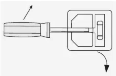
b) Exchanging the fuse
If it is no longer possible to switch on the laboratory power unit, the rear mains fuse (11) is probably defective.
Proceed as follows to replace the mains fuse:
- Switch off the power unit and remove all the connection cables and the mains plug from the device.
- Lever the rear fuse holder (11) with a suitable screwdriver from the bracket.
- Replace the defective fuse with a new fine-wire fuse of the same type and rated current. The fuse value is listed in the chapter on "Technical data".
- Press the fuse into the fuse holder.

Fuses are replacement parts and not covered by the warranty/guarantee.
20. TROUBLESHOOTING
By purchasing the laboratory power unit, you have acquired a product that is reliable and operationally safe.
Nevertheless, problems or errors may occur.
For this reason we want to describe how to troubleshoot potential malfunctions:

Always follow the safety instructions!
| Error Possible cause | |
| The power unit cannot be switched on. | ·Does the indicator C.V. or C.C. light up? ·Check the mains voltage (you may also want to check the mains fuse in the device or the line circuit breaker). |
| Connected consumer devices do not work. | ·Is the voltage set correctly? ·Ils the polarity correct? ·Check the technical data of the consumers. |
| The control indicator REMOTE is lit. The device can not be operated via the rotary controls. | Remote control operation is active. |
| The control indicator C.C. is lit. Constant current operation: The preset current was exceeded. Check power consumption on your consumer and increase the current limitation on your power unit, if applicable. | |
| The control indicator C.V. LED is lit. Constant voltage operation The power unit works normally. The output provides the constant voltage set. | |
| Display “OVP” Over-voltage protection: See chapter “protective measures”. | |
| Display “OtP” Over-voltage protection: See chapter “protective measures”. | |
| Display “OLP” Over-voltage protection: “See chapter protective measures”. | |

Other inspections than those described above may only be carried out by an authorised specialist. If you have any questions concerning the handling of the device, please do no hesitate to contact our Technical support.
21. DECLARATION OF CONFORMITY (DOC)
We, Conrad Electronic SE, Klaus-Conrad-Straße 1, D-92240 Hirschau, hereby declare that this product conforms to the fundamental requirements and the other relevant regulations of the directive 1999/5/EC.

The Declaration of Conformity for this product can be found at www.conrad.com.
22. DISPOSAL

Electronic devices are recyclable waste and must not be disposed of in the household waste.
end of its service life, dispose of the product according to the relevant statutory regulations.

us fulfil your statutory obligations and contribute to the protection of the environment.
23. TECHNICAL DATA
| Item no. 1367575 1367576 | ||
| Type CPPS-320-42 CPPS-320-84 | ||
| Operating voltage | 100 - 240 V/AC, 45 - 65 Hz | |
| Max. input current (230 V/AC) | <1,8 A | |
| Maximum output power | 320 W | |
| Output voltage | 0 - 42 V/DC 0 - 84 V/DC | |
| Output current | 0 - 20 A 0 - 10 A | |
| Voltage control response at 10 - 100 % load change | ≤ 80 mV | |
| Voltage control response at mains fluctuation (90 - 264 V/AC) | ≤ 10 mV | |
| Current control response at 10 - 90% load change | ≤ 50 mA | |
| Current control response at mains fluctuation (90 - 264 V/AC) | ≤ 10 mA | |
| Display accuracy | ±(0,2% + 5 counts) V/A | |
| Degree of effectiveness | 85% | |
| Clock signal | 44 to 55 kHz | |
| Performance factor with active PFC | ≥ 0,9 | |
| Device fan | Temperature controlled (0 - 100%) | |
| Mains fuse slow-blow (5 x 20 mm) | T3.15AL250V | |
| Operating temperature | 0 °C to +40 °C | |
| Operating humidity | 10% to 80%, non-condensing | |
| Storage temperature | -15 °C to +70 °C | |
| Storage humidity | 10% to 85%, non-condensing | |
| Operating altitude | max. 2000 m above mean sea level (N.N.) | |
| Safety class | I | |
| Weight | 2,3 kg | |
| Dimensions (W x H x D) | 200 x 95 x 245 mm | |
TABLE DES MATIÈRES

Page
Chere cliente, cher client,
France (email): technique@conrad-france.fr
External Timed Program
Data Log Setting


-SettingFunc.AB.C
| A | B | C | |
| Voltage(V) | 0 | 9 | 3 |
| Current(A) | 5 | 7 | 9 |
| Time(S) | 2 | 1 | 3 |
ABCRecals

Setting Transit Time
| A-B | B-A | A-C | C-A | B-C | C-B |
| 0 | 0 | 2 | 2 | 2 | 2 |
Run

WaveForm Preview set
External Timed Program
Data Log
Setting


Setting Func.A,B,C
| A | B | C | |
| Voltage(V) | 5 | 10 | 3 |
| Current(A) | 5 | 7 | 9 |
| Time(S) | 3 | 3 | 3 |
ABC Recalls

- Setting Transit Time
| A.B | B.A | A.C | C.A | B.C | C.B |
| 3 | 3 | 4 | 0 | 3 | 0 |
Run

Wave Form Preview set
External getimede programming 131
External Timed Program
DataLog Setting

-SettingFunc.AB.C
| A | B | C | |
| Voltage(V) | 0 | 9 | 3 |
| Current(A) | 5 | 7 | 9 |
| Time(S) | 2 | 1 | 3 |
AECRecals

Setting Transit Time
| Δ-B | E-A | Δ-C | C-A | B-C | C-B |
| 0 | 0 | 2 | 2 | 2 | 2 |
Run

Wave Form Preview set
External Timed Program
Data Log | Setting

Setting Func.A,B,C
| A | B | C | |
| Voltage(V) | 5 | 10 | 3 |
| Current(A) | 5 | 7 | 9 |
| Time(S) | 3 | 3 | 3 |
ABC Recalls

Setting Transit Time
| A·B | B·A | A·C | C·A | B·C | C·B |
| 3 | 3 | 4 | 0 | 3 | 0 |
WaveForm Preview set
Extern getimede programming
Running Cycle: Aantal cycli 0 - 9999 / 0 = oneindig
Copyright 2015 by Conrad Electronic SE.

Legal Notice
This is a publication by Conrad Electronic SE, Klaus-Conrad-Str. 1, D-92240 Hirschau (www.conrad.com).
All rights including translation reserved. Reproduction by any method, e.g. photocopy, microfilming, or the capture in electronic data processing systems require the prior written approval by the editor. Reprinting, also in part, is prohibited. This publication represent the technical status at the time of printing.
Copyright 2015 by Conrad Electronic SE.

Information legales
Copyright 2015 by Conrad Electronic SE.

Colofon
Copyright 2015 by Conrad Electronic SE. V1_0815_02/VTP
- page
- INTRODUCTION
- INTENDED USE
- DELIVERY CONTENT
- SYMBOL EXPLANATION
- a) Persons / Product
- b) Miscellaneous
- OPERATING ELEMENTS
- a) Connecting the power cable
- b) Setting up the device
- c) General information
- NORMAL OPERATION
- a) Set current limit
- b) Set output voltage
- c) Connecting a consumer
- FUNCTION BUTTONS
- a) Key lock function
- b) Manual output ON/OFF
- c) Adjustable ammeter / watt-meter
- “PRESET” MEMORY LOCATION OPERATION
- Please ensure that no consumers are connected.
- If you change the preset voltage and current values, these values are stored, if the laboratory power supply is switched off. Always test the values set before connecting a consumer.
- a) Presetting the DC voltage source
- b) Setting the V / value
- For example:
- A/B/C FUNCTION AND CURVE GENERATOR
- Example 1:
- Example 2:
- REMOTE CONTROL
- a) Preparing the remote control connection
- b) Control via the external voltage source
- Voltage setting "V" Current setting "I":
- c) Control via controllable resistance (potentiometer)
- d) Output remote control (on/off)
- RESETTING THE FACTORY SETTINGS
- SENSE FUNCTION
- SOFTWARE INSTALLATION
- CONTROL WITH PC SOFTWARE
- Example 1 of the preview of the waveform:
- Example 2 of the preview of the waveform:
- Example 3 of the preview of the waveform:
- External timed program
- Window for externally timed programming
- Procedure
- PROTECTIVE MEASURES
- a) Over-voltage protection
- b) Overheating protection
- c) Overload protection
- MAINTENANCE AND CLEANING
- a) General
- b) Exchanging the fuse
- TROUBLESHOOTING
- Always follow the safety instructions!
- DECLARATION OF CONFORMITY (DOC)
- DISPOSAL
- TECHNICAL DATA
- TABLE DES MATIÈRES
- Extern getimede programming
- Legal Notice
- Information legales
- Colofon
Brand : VOLTCRAFT
Model : CPPS32084
Category : Laboratory power supply