PF3054 - Pressure sensor IFM - Free user manual and instructions
Find the device manual for free PF3054 IFM in PDF.

| Product type | Pressure sensor |
| Brand | IFM |
| Model | PF3054 |
| Measuring range | 0...10 bar (for PF3054) |
| Overload pressure | 50 bar |
| Burst pressure | 150 bar |
| Supply voltage | 20...30 V DC |
| Output current | max. 250 mA |
| Analog output | 4...20 mA |
| Analog signal accuracy | < ± 1.0% of measuring range |
| Display | Digital 4 digits (display 1%...105%) |
| Electrical connection | M12x1, 4-wire |
| Materials in contact with fluid | Stainless steel 316L, ceramic, FPM (Viton), PTFE |
| Housing | Stainless steel 316L, Pocan, PC (Macrolon), PA, EPDM/X (Santoprene), FPM (Viton) |
| Protection | IP67 |
| Ambient temperature | -25...+80 °C |
| Fluid temperature | -25...+80 °C |
| Dimensions | Ø34 x 84.5 mm |
| Weight (estimated) | ~100 g |
| Switching functions | Hysteresis or window, NO/NC |
| Adjustable parameters | SP1, rP1, dS1, dr1, OU1, dAP |
| Mounting | Adaptable to different process connections (separate ifm adapters) |
| Cleaning | Screw-off filter cover for cleaning |
| Safety | Do not exceed overload pressure; check material compatibility |
| Spare parts | ifm process adapters, O-rings |
Frequently Asked Questions - PF3054 IFM
User questions about PF3054 IFM
0 question about this device. Answer the ones you know or ask your own.
Ask a new question about this device
Download the instructions for your Pressure sensor in PDF format for free! Find your manual PF3054 - IFM and take your electronic device back in hand. On this page are published all the documents necessary for the use of your device. PF3054 by IFM.
USER MANUAL PF3054 IFM
Combi-Drucksensor Combined pressure sensor
natural_image
Technical line drawing of a mechanical device with no visible text or symbols| InhaltSicherheitshinweise . . . . . . . . . . . . . . . . . . . . . . . . . . . . . . . . . . . . . . . . . . . . . . . . . . . . . . . . . . . . . . . . . . . . . . . . . . . . . . . . . . . . . . . . . . . . . . . . . . . . 1. Bestimmungsgemäße Verwendung . . . . . . . . . . . . . . . . . . . . . . . . . . . . . . . . . . . . . . . . . . . . . . . . . . . . . . . . . . . . . . . . . . . . . . . . . . . . . . . . . . . . . . . . . . . . . . . . . . .2. Betriebsarten . . . . . . . . . . . . . . . . . . . . . . . . . . . . . . . . . . . . . . . . . . . . . . . . . . . . . . . . . . . . . . . . . . . . . . . . . . . . . . . . . . . . . . . . . . . . . . . . . . . Montage . . . . . . . . . . . . . . . . . . . . . . . . . . . . . . . . . . . . . . . . . . . . . . . . . . . . . . . . . . . . . . . . . . . . . . . . . . . . . . . . . . . . . . . . . . . . . . . . . . .4. Elektrischer Anschluß . . . . . . . . . . . . . . . . . . . . . . . . . . . . . . . . . . . . . . . . . . . . . . . . . . . . . . . . . . . . . . . . . . . . . . . . . . . . . . . . . . . . . . . . . . . . . . . . . . . Einstellbare Parameter . . . . . . . . . . . . . . . . . . . . . . . . . . . . . . . . . . . . . . . . . . . . . . . . . . . . . . . . . . . . . . . . . . . . . . . . . . . . . . . . . . . . . . . . . . . . . . . . . . . Programmieren . . . . . . . . . . . . . . . . . . . . . . . . . . . . . . . . . . . . . . . . . . . . . . . . . . . . . . . . . . . . . . . . . . . . . . Inbetriebnahme / Betrieb . . . . . . . . . . . . . . . . . . . . . . . . . . . . . . . . . . . . . . . . . Technische Daten . . . . . . . . . . . . . . . . . . . . . . . . . . . . . . Maßzeichnung . . . . . . . . . . . . . . . . . . . . . . . . | DEUTSCH | |
| ContentsSafety instructions ...... page 16Controls and visual indication ...... page 161. Function and features ...... page 172. Operating modes ...... page 193. Installation ...... page 204. Electrical connection ...... page 225 .Adjustable parameters ...... page 226. Programming ...... page 247. Installation and set-up / operation ...... page 258. Technical data ...... page 269. Scale drawing ...... page 27 | ENGLISH |
M = Mode/Enter
S = Set
Sicherheitshinweise
line
| t | P | rP | | ---- | ----- | ---- | | 0 | 0 | 0 | | 1 | 1 | 0 | | 2 | 1 | 0 | | 3 | 1 | 0 | | 4 | 1 | 0 | | 5 | 1 | 0 | | 6 | 1 | 0 | | 7 | 1 | 0 | | 8 | 1 | 0 | | 9 | 1 | 0 | | 10 | 1 | 0 | | 11 | 1 | 0 | | 12 | 1 | 0 | | 13 | 1 | 0 | | 14 | 1 | 0 | | 15 | 1 | 0 | | 16 | 1 | 0 | | 17 | 1 | 0 | | 18 | 1 | 0 | | 19 | 1 | 0 | | 20 | 1 | 0 | | 21 | 1 | 0 | | 22 | 1 | 0 | | 23 | 1 | 0 | | 24 | 1 | 0 | | 25 | 1 | 0 | | 26 | 1 | 0 | | 27 | 1 | 0 | | 28 | 1 | 0 | | 29 | 1 | 0 | | 30 | 1 | 0 | | 31 | 1 | 0 | | 32 | 1 | 0 | | 33 | 1 | 0 | | 34 | 1 | 0 | | 35 | 1 | 0 | | 36 | 1 | 0 | | 37 | 1 | 0 | | 38 | 1 | 0 | | 39 | 1 | 0 | | 40 | 1 | 0 | | 41 | 1 | 0 | | 42 | 1 | 0 | | 43 | 1 | 0 | | 44 | 1 | 0 | | 45 | 1 | 0 | | 46 | 1 | 0 | | 47 | 1 | 0 | | 48 | 1 | 0 | | 49 | 1 | 0 | | 50 | 1 | 0 | | 51 | 1 | 0 | | 52 | 1 | 0 | | 53 | 1 | 0 | | 54 | 1 | 0 | | 55 | 1 | 0 | | 56 | 1 | 0 | | 57 | 1 | 0 | | 58 | 1 | 0 | | 59 | 1 | 0 | | 60 | 1 | 0 | | 61 | 1 | 0 | | 62 | 1 | 0 | | 63 | 1 | 0 | | 64 | 1 | 0 | | 65 | 1 | 0 | | 66 | 1 | 0 | | 67 | 1 | 0 | | 68 | 1 | 0 | | 69 | 1 | 0 | | 70 | 1 | 0 | | 71 | 1 | 0 | | 72 | 1 | 0 | | 73 | 1 | 0 | | 74 | 1 | 0 | | 75 | 1 | 0 | | 76 | 1 | 0 | | 77 | 1 | 0 | | 78 | 1 | 0 | | 79 | 1 | 0 | | 80 | 1 | 0 | | Note: The data is extracted from the code and presented in CSV format as requested. The 'H' values are not explicitly provided in the code. The 'p' values are calculated based on the formula 'SP' and 'rP'. The 'H' values are calculated using the formula 'Hsterese'.line
| t | P | rP | | ---- | ----- | ---- | | 0 | 0 | 0 | | 1 | 1 | 1 | | 2 | 0 | 0 | | 3 | 0 | 0 | | 4 | 0 | 0 | | 5 | 0 | 0 | | 6 | 0 | 0 | | 7 | 0 | 0 | | 8 | 0 | 0 | | 9 | 0 | 0 | | 10 | 0 | 0 | | 11 | 0 | 0 | | 12 | 0 | 0 | | 13 | 0 | 0 | | 14 | 0 | 0 | | 15 | 0 | 0 | | 16 | 0 | 0 | | 17 | 0 | 0 | | 18 | 0 | 0 | | 19 | 0 | 0 | | 20 | 0 | 0 | | 21 | 0 | 0 | | 22 | 0 | 0 | | 23 | 0 | 0 | | 24 | 0 | 0 | | 25 | 0 | 0 | | 26 | 0 | 0 | | 27 | 0 | 0 | | 28 | 0 | 0 | | 29 | 0 | 0 | | 30 | 0 | 0 | | 31 | 0 | 0 | | 32 | 0 | 0 | | 33 | 0 | 0 | | 34 | 0 | 0 | | 35 | 0 | 0 | | 36 | 0 | 0 | | 37 | 0 | 0 | | 38 | 0 | 0 | | 39 | 0 | 0 | | 40 | 0 | 0 | | 41 | 0 | 0 | | 42 | 0 | 0 | | 43 | 0 | 0 | | 44 | 0 | 0 | | 45 | 0 | 0 | | 46 | 0 | 0 | | 47 | 0 | 0 | | 48 | 0 | 0 | | 49 | 0 | 0 | | 50 | 0 | 0 | | 51 | 0 | 0 | | 52 | 0 | 0 | | 53 | 0 | 0 | | 54 | 0 | 0 | | 55 | 0 | 0 | | 56 | 0 | 0 | | 57 | 0 | 0 | | 58 | 0 | 0 | | 59 | 0 | 0 | | 60 | 0 | 0 | | 61 | 0 | 0 | | 62 | 0 | 0 | | 63 | 0 | 0 | | 64 | 0 | 0 | | 65 | 0 | 0 | | 66 | 0 | 0 | | 67 | 0 | 0 | | 68 | 0 | 0 | | 69 | 0 | 0 | | 70 | 0 | 0 | | 71 | 0 | 0 | | 72 | 0 | 0 | | 73 | 0 | 0 | | 74 | 0 | 0 | | 75 | 0 | 0 | | 76 | 0 | 0 | | 77 | 0 | 0 | | 78 | 0 | 0 | | 79 | 0 | 0 | | 80 | 0 | 0 | | Note: The actual values for 'SP' and 'rP' are not provided in the code. The 'Fno' and 'Fnc' labels appear above the plot area. There is only one data series labeled 'Gutbereich'.2. Betriebsarten
Run-Modus:
natural_image
Simple line drawing of a printer with a hand gesture pointing to it (no text or symbols)Schritt 3
1 = BN (braun),
2 = WH (weiß)
3 = BU (blau),
4 = BK (schwarz).
5 Einstellbare Parameter
Please read the product description prior to installing the unit. Please check that the product is suitable for your application without any restrictions.
If the operating instructions or the technical data are not adhered to, personal injury and/or damage to property may occur.
Please check in all applications that the product materials (see Technical data) are compatible with the media to be measured.
Controls and visual indication
![8.8.8 Mode/Enter Set [bar] ① ② ③ ④](/content/2026/04/598811/images/a5d3541e8df9201361779abf9cfe4733550f09d6f7bd7163c8117f349d225478.jpg)
| 1 | LED display | display of the system pressure, display of parameters and parameter values |
| 2 | LED red | switching status;lights if the output has switched |
| 3 | Mode / Enter button | selection of the parameters and acknowledgement of the parameter values |
| 4 | Set button | setting of the parameter values (scrolling by holding pressed; incremental by pressing briefly) |
1. Function and features
- The pressure sensor detects the system pressure,
• shows the current system pressure on its display (indication as from 1% to 105% of the value of the measuring range), - and generates 2 output signals according to the set output configuration.
| output 1 | output 2 |
| hysteresis function / N.O. (Hno) | analog 4 ... 20 mA |
| hysteresis function / N.C. (Hnc) | |
| window function / N.O. (Fno) | |
| window function / N.C. (Fnc) |
The unit is EHEDG 3A certified
Applications
Type of pressure: relative pressure
| Measuring range | Order no.overl. pressure | Bursting pressure | |
| PF30x3 0 ... | 25 bar 100 bar 350 | bar | |
| PF30x4 0 ... | 10 bar 50 bar 150 | bar | |
| PF30x6 0 ... | 2,5 bar 20 bar 50 | bar | |
| PF30x7 0 ... | 1 bar 10 bar 30 | bar | |
| PF30x8 0 ... | 250 mbar | 10 bar 30 bar |

Avoid static and dynamic overpressure exceeding the given overload pressure.
Even if the bursting pressure is exceeded only for a short time the unit can be destroyed (danger of injuries)!

Indication of the current system pressure as from 1% of the value of the measuring range. Display "0" does not mean that the system is free of pressure!
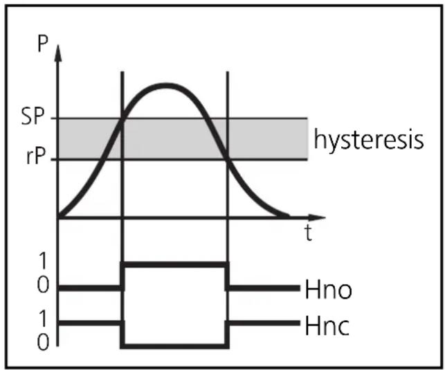
Hysteresis:
The hysteresis keeps the switching state of the output stable if the system pressure varies about the preset value. When the system pressure is rising, the output switches when the switch-on point has been reached (SP1); when the system pressure is falling again, the output switches back when the switch-off point (rP1) has been reached.
line
| t | P | | ---- | ----- | | 0 | 0 | | 1 | 1 | | 2 | 1 | | 3 | 1 | | 4 | 1 | | 5 | 1 | | 6 | 1 | | 7 | 1 | | 8 | 1 | | 9 | 1 | | 10 | 1 | | 11 | 1 | | 12 | 1 | | 13 | 1 | | 14 | 1 | | 15 | 1 | | 16 | 1 | | 17 | 1 | | 18 | 1 | | 19 | 1 | | 20 | 1 | | 21 | 1 | | 22 | 1 | | 23 | 1 | | 24 | 1 | | 25 | 1 | | 26 | 1 | | 27 | 1 | | 28 | 1 | | 29 | 1 | | 30 | 1 | | 31 | 1 | | 32 | 1 | | 33 | 1 | | 34 | 1 | | 35 | 1 | | 36 | 1 | | 37 | 1 | | 38 | 1 | | 39 | 1 | | 40 | 1 | | 41 | 1 | | 42 | 1 | | 43 | 1 | | 44 | 1 | | 45 | 1 | | 46 | 1 | | 47 | 1 | | 48 | 1 | | 49 | 1 | | 50 | 1 | | 51 | 1 | | 52 | 1 | | 53 | 1 | | 54 | 1 | | 55 | 1 | | 56 | 1 | | 57 | 1 | | 58 | 1 | | 59 | 1 | | 60 | 1 | | 61 | 1 | | 62 | 1 | | 63 | 1 | | 64 | 1 | | 65 | 1 | | 66 | 1 | | 67 | 1 | | 68 | 1 | | 69 | 1 | | 70 | 1 | | 71 | 1 | | 72 | 1 | | 73 | 1 | | 74 | 1 | | 75 | 1 | | 76 | 1 | | 77 | 1 | | 78 | 1 | | 79 | 1 | | 80 | 1 | | 81 | 1 | | 82 | 1 | | 83 | 1 | | 84 | 1 | | 85 | 1 | | 86 | 1 | | 87 | 1 | | 88 | 1 | | 89 | 1 | | 90 | 1 | | 91 | 1 | | 92 | 1 | | 93 | 1 | | 94 | 1 | | 95 | 1 | | 96 | 1 | | 97 | 1 | | 98 | 1 | | 99 | 1 | | Note: The y-axis label 'SP' and 'rP' are estimated based on the code provided in the code. The 'hysteresis' annotation is not used in the plot. The 'Hno' and 'Hnc' labels are not present in the plot. The 't' axis is labeled 't'.The hysteresis can be set: First the switch-on point is set, then the switch-off point with the requested difference.
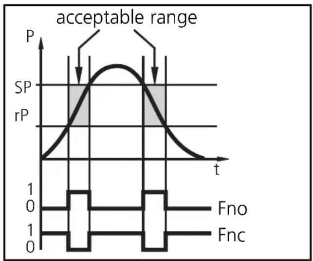
Window function:
The window function enables the monitoring of a defined acceptable range. When the system pressure varies between the switch-on point (SP1) and the switch-off point (rP1), the output is switched (window function / NO) or not switched (window function / NC).
The width of the window can be set by means of the difference
between SP1 and rP1. SP1 = upper value, rP1 = lower value.
line
| t | P | SP | rP | | ---- | ----- | ----- | ----- | | 0 | 0 | 0 | 0 | | 1 | 1 | 1 | 0 | | 2 | 0 | 0 | 1 | | 3 | 0 | 0 | 0 | | 4 | 0 | 0 | 0 | | 5 | 0 | 0 | 0 | | 6 | 0 | 0 | 0 | | 7 | 0 | 0 | 0 | | 8 | 0 | 0 | 0 | | 9 | 0 | 0 | 0 | | 10 | 0 | 0 | 0 | | 11 | 0 | 0 | 0 | | 12 | 0 | 0 | 0 | | 13 | 0 | 0 | 0 | | 14 | 0 | 0 | 0 | | 15 | 0 | 0 | 0 | | 16 | 0 | 0 | 0 | | 17 | 0 | 0 | 0 | | 18 | 0 | 0 | 0 | | 19 | 0 | 0 | 0 | | 20 | 0 | 0 | 0 | | 21 | 0 | 0 | 0 | | 22 | 0 | 0 | 0 | | 23 | 0 | 0 | 0 | | 24 | 0 | 0 | 0 | | 25 | 0 | 0 | 0 | | 26 | 0 | 0 | 0 | | 27 | 0 | 0 | 0 | | 28 | 0 | 0 | 0 | | 29 | 0 | 0 | 0 | | 30 | 0 | 0 | 0 | | 31 | 0 | 0 | 0 | | 32 | 0 | 0 | 0 | | 33 | 0 | 0 | 0 | | 34 | 0 | 0 | 0 | | 35 | 0 | 0 | 0 | | 36 | 0 | 0 | 0 | | 37 | 0 | 0 | 0 | | 38 | 0 | 0 | 0 | | 39 | 0 | 0 | 0 | | 40 | 0 | 0 | 0 | | 41 | 0 | 0 | 0 | | 42 | 0 | 0 | 0 | | 43 | 0 | 0 | 0 | | 44 | 0 | 0 | 0 | | 45 | 0 | 0 | 0 | | 46 | 0 | 0 | 0 | | 47 | 0 | 0 | 0 | | 48 | 0 | 0 | 0 | | 49 | 0 | 0 | 0 | | 50 | 1 | -1 | -1 | | | | | | | | | | | | | | | | | | | | | | | | | | | | | | | | | | | | | | | | | | | | | | | | | | | | | | | | | | | | | | | | | | | | | | | | | | | | | | | | | | | | | | | | | | | | | | | | | | | | | | | | | | | | | | | | | | | | | | | | | | | | | | | | | | | | | | | | | | | | | | | | | | | | | | | | | | | | | | | | | | | | | | | | | | | | | | | | | | | | | | | | | | | | | | | | | | | | | | | | | | | | | | | | | | | | | | | | | | | | | | | | | | |2. Operating modes
Run mode:
(Normal operating mode)
When the supply voltage has been applied, the unit is in the Run mode. It monitors and switches the transistor output according to the set parameters. The value of the analog output depends on the system pressure.
The display shows the current system pressure, the red LED indicates the switching state of the output.
Display mode:
(Indication of parameters and the set parameter values)
When the "Mode/Enter" button is pressed for a short time, the unit passes to the Display mode. Internally it remains in the operating mode. Irrespective of this the set parameter values can be read:
- The parameter names are scrolled with each pressing of the "Mode/Enter" button.
- When the "Set" button is pressed for a short time, the corresponding parameter value is displayed for approx. 5s; then the unit returns to the Run mode.
Programming mode:
(Setting of the parameter values)
The unit passes to the programming mode when after the selection of a parameter value (Display mode) the "Set" button is pressed until the display of the parameter value is changed. Internally the unit remains in the operating mode. It continues its monitoring function with the existing parameters until the change has been terminated.
You can change the parameter value by pressing the "Set" button and confirm it by pressing the "Mode/Enter" button. The unit returns to the Run mode when no button has been pressed for 5s.
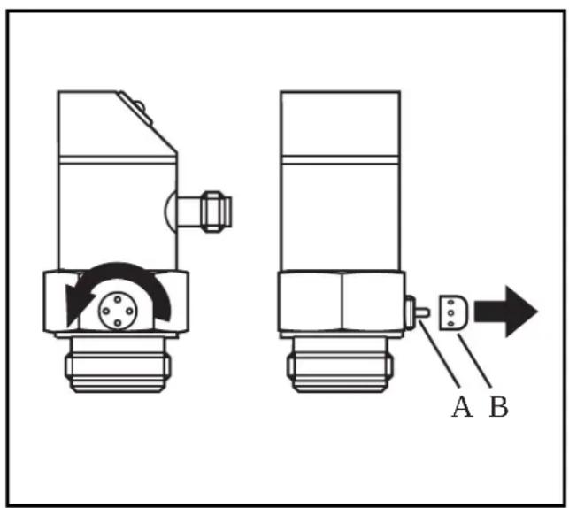
3. Installation

Before mounting and removing the sensor, make sure that no pressure is applied to the system.
The unit is adaptable for various process fittings. ifm adapters to be ordered separately as accessories.
The housing (A) is freely rotatable.
Prozess adapter:
Mount adapter (C) to the sensor first, then sensor + adapter to the process connection by means of a nut, a clamping flange or similar (B).
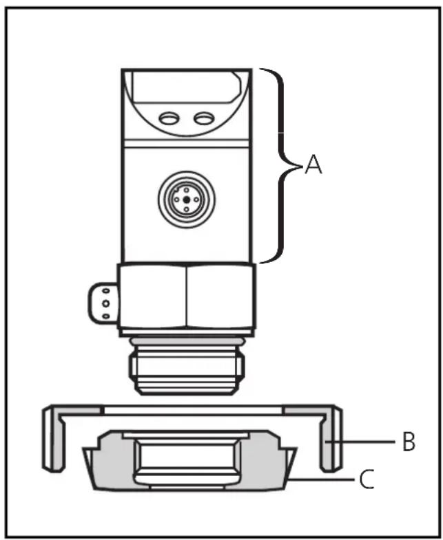
If it is not possible to slide the fixing element (B) down over the top of the sensor: slide it up over the bottom of the sensor before the adapter is mounted.

Sensor and adapter are only to be mounted once.
If it is not possible to slide the fixing element (B) down over the top of the sensor: slide it up over the bottom of the sensor before the adapter is mounted.
Welding adapter:
Weld the adapter first. Then mount the sensor.
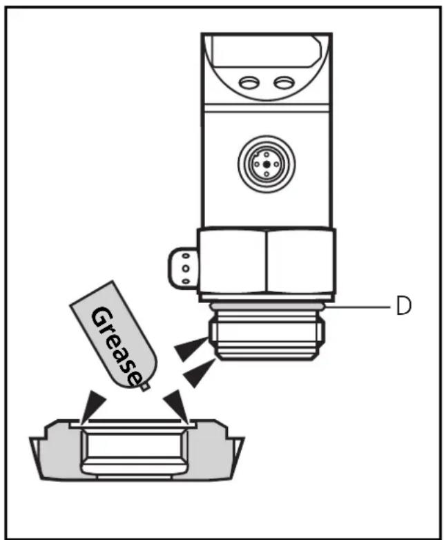
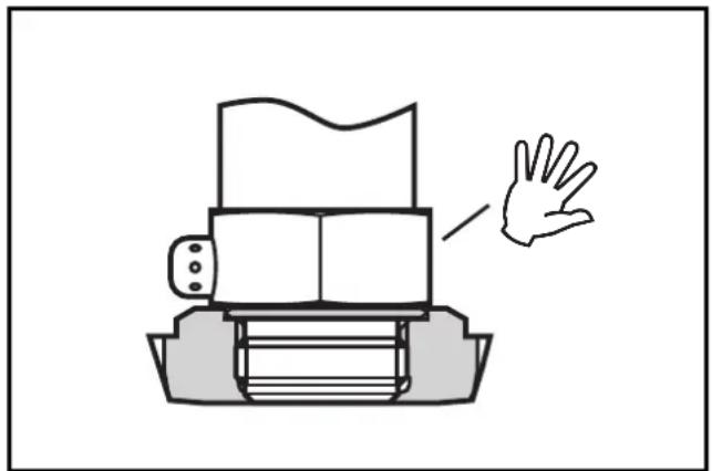
Mounting of the adapter Step 1
Grease thread and sealing chamfer of the sensor and of the adapter with the greasing paste supplied.
The greasing paste is food-grade (USDA-H1 84-201).
Make sure that the O-ring (D) is correctly positioned.
Step 2
Screw the sensor into the adapter. Avoid mechanical influence on the sealing chamfers.
natural_image
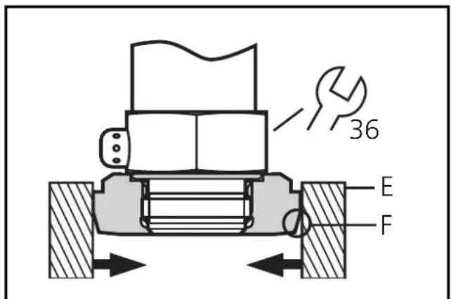
Simple line drawing of a printer with a hand gesture pointing to it (no text or symbols)Step 3
Clamp sensor and adapter into a clamping device (E). The sealing chamfers (F) must not be damaged. Tighten the sensor with a spanner until you can feel the end stop.
Note: If you continue to turn, this can have adverse effect on the sealing.
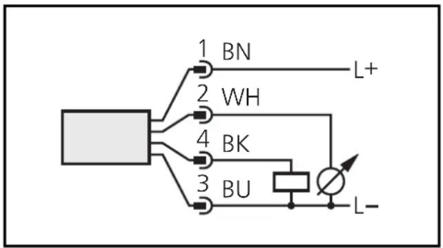
4. Electrical connection
The unit must only be connected by an electrician.
The national and international regulations for the installation of electrical equipment must be observed.
Voltage supply to EN50178, SELV, PELV.
Disconnect power before connecting the unit.
Wiring:
flowchart
graph TD
    A["Ground"] --> B["1 BN"]
    A --> C["2 WH"]
    A --> D["4 BK"]
    A --> E["3 BU"]
    B --> F["L+"]
    C --> G["Ground Symbol"]
    D --> H["Ground Symbol"]
    E --> I["Ground Symbol"]
Core colours of ifm sockets:
1 = BN (brown),
2 = WH (white),
3 = BU (blue),
4 = BK (black).
5. Adjustable parameters
(Menu structure: see fold out page)
| SP1 | Switch-on point: Upper limit value at which the output changes its switching status.· setting range 1 ... 100% of the value of the measuring range· in steps of 0.5% of the value of the measuring range· indicated in bar |
| rP1 | Switch-off point: Lower limit value at which the output changes its switching status.· setting range 0.5 ... 99.5% of the value of the measuring range· in steps of 0.5% of the value of the measuring range· indicated in barrP1 is always lower than SP1. The unit only accepts values which are 0.5% lower than SP1.Changing the switch-on point also changes the switch-off point (the distance between SP1 and rP1 remains constant).If the distance is higher than the new switch point, it is automatically reduced (rP1 is set to the minimum setting value). |
| d51dr1 | Delay time for the switching outputdS1 = switch-on delay; dr1 = switch-off delayThe output does not immediately change its switching status when the switching condition is met but when the delay time has elapsed. If the switching condition is no longer met when the delay time has elapsed, the switching state of the output does not change.· setting range: 0 - 0.2 - 0.4 ... 9.8 - 10 - 11 - ... - 49 - 50s· in steps of 0.2 or 1s· indicated in seconds | |||||||||
| OU1 | Switching functions of the switching output4 settings can be selected:Hno = hysteresis / normally openHnc = hysteresis / normally closedFno = window function / normally openFnc = window function / normally closed | |||||||||
| dAP | Damping for the switching outputPressure peaks of short duration or high frequency can be filtered out.dAP-value = response time between pressure change and change of the switching status in ms.· the value for dAP defines the switching frequency (f) of the output: | |||||||||
| dAP | 3 | 6 | 10 | 17 | 30 | 60 | 125 | 250 | 500 | |
| f [Hz] | 170 | 80 | 50 | 30 | 16 | 8 | 4 | 2 | 1 | |
6. Programming
Take the following 3 steps for programming:
| 1 |  |  | 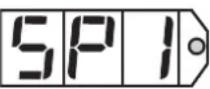 | Press the Mode/Enter button several times until the respective parameter is displayed. |
| 2 |  | [A235] |  | Press the Set button and keep it pressed. The current parameter value is indicated for 5s, then the value is increased* (incremental by pressing briefly or scrolling by holding pressed). |
| 3 |  |  | 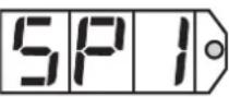 | Press the Mode/Enter button briefly (= acknowledgement). The parameter is displayed again, the set parameter value becomes effective. |
| Wait 5s (the unit passes to the operating mode and the current measured value is indicated again), or start again with step 1 to program other parameters. | ||||
*Decrease the value: Let the display of the parameter value move to the maximum setting value. Then the cycle starts again at the minimum setting value.
If no button is pressed for 20s during the setting procedure, the unit returns to the run mode.
Locking / Unlocking
The unit can be electronically locked to prevent unwanted adjustment of the set parameters: Press (in Run mode) both setting buttons for 10s. As soon as the indication goes out the unit is locked or unlocked. Units are delivered from the factory in the unlocked state.
With the unit in the locked state is indicated briefly when you try to change parameter values.
7. Installation and set-up / operation
After mounting, wiring and setting check whether the unit operates correctly.
Faults displayed during operation:
| OL | = overload pressure(system pressure > 110% of the max. nominal pressure) |
| SCI | (flashing) = short-circuit in the switching output;the output is switched off |
Cleaning of the filter cover
If viscous and residues producing media clog the filter cover of the sensor (and thus reduce the measuring accuracy slightly), you can clean it.
Unscrew the filter cover (B) (use a pair of pliers with plastic-covered jaws for this). Clean the cover thoroughly.
The vent (A) should only be cleaned by skilled personnel and with utmost care.

Possible medium residues must not be compressed and pressed into the vent. This could clog the filter system and reduce the measuring accuracy of the sensor.
Screw the filter cover again tightly.
The sensor is sufficiently protected against harsh ambient conditions (protection IP 67). The protection rating can be increased by a special accessory (order no. E30043).
8. Technical data
| Operating voltage [V] . . . . . . . . . . . . . . . . . . . . . . . . . . . . . . . . . . . . . . . . . . . . . . . . . . . . . . . . . . . . . . . . . . . . . . . . . . . . . . . . . . . . . . . . . . . . . . . . . . . . 20 ... 30 DCCurrent rating [mA]. . . . . . . . . . . . . . . . . . . . . . . . . . . . . . . . . . . . . . . . . . . . . . . . . . . . . . . . . . . . . . . . . . . . . . . . . . . . . . . . . . . . . . . . . . . . . . . . . . . . short-circuit protection, reverse polarity protection / overload protection, integrated WatchdogVoltage drop [V]. . . . . . . . . . . . . . . . . . . . . . . . . . . . . . . . . . . . . . . . . . . . . . . . . . . . . . . . . . . . . . . . . . . . . . . . . . . . . . . . . . . . . . . . . . . . . . . . . . . < 2Current consumption [mA] . . . . . . . . . . . . . . . . . . . . . . . . . . . . . . . . . . . . . . . . . . . . . . . . . . . . . . . . . . . . . . . . . . . . . . . . . . . . . . . . . . . . . . . . . . . . . . . Analog output . . . . . . . . . . . . . . . . . . . . . . . . . . . . . . . . . . . . . . . . . . . . . . . . . . . . . . . . . . . . . . . . . . . . . . . . . . . . . . . . . . . . . . . . . . . . . . . . . . . max. 500 |
| Characteristics deviation [% of value of measuring range] . . . . . . . . . . . . . . . . . . . . . . . . . . . . . . . . . . . . . . . . . . . . . . . . . . . . . . . . . . . . . . . . . . . . . . . . . . . . . . . . . . . . . . . . . . . . . . . . . . Repeatability [% of value of measuring range] . . . . . . . . . . . . . . . . . . . . . . . . . . . . . . . . . . . . . . . . . . . . . . . Accuracy of switch point [% of value of measuring range] . . . . . . . . . . . . . . . . . . . . . . . . . . . . Temperature drift [% of value of measuring range / 10 K] . . . . . . . . . . . . . . . in the temperature range [°C]. . . . . . . . . . . . . . . . . . . . . . . . -25 ... +80Power-on delay time [s] . . . . . . . . . . . . . . . . . . . . . . . . . . . Response time analog output [ms] . . . . . . . . . . . . . . . . . . 3 |
| Materials (wetted parts) . . . . . . . . . stainless steel (316S12); ceramics; FPM (Viton); PTFEHousing material . . . . . . stainless steel (316S12); Pocan; PC (Macrolon); PA; EPDM/X (Santoprene); FPMProtection IP 67Protection class. IIIInsulation resistance [MΩ] > 100 (500 V DC)Shock resistance [g] 50 (DIN / IEC 68-2-27, 11ms)Vibration resistance [g] 20 (DIN / IEC 68-2-6, 10 - 2000 Hz)Switching cycles min. 100 millionAmbient temperature [°C] -25 ... +80Medium temperature [°C] -25 ... +80Storage temperature [°C] -40 ... +100EMCIEC 1000/4/2 ESD: 4 / 8 KVIEC 1000/4/3 HF radiated: 10 V/mIEC 1000/4/4 Burst: 2 KVIEC 1000/4/6 HF conducted: 10 V |
*0.4% for PF30x8
9. Scale drawing
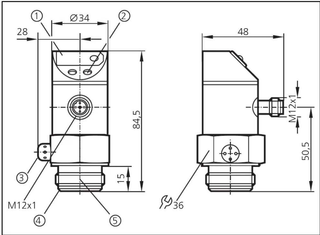
① 7-segment display
② programming button
③ filter cover
④ sealing edge
⑤ ifm thread for connection to ifm process adapter
natural_image
Simple line drawing of a printer with a hand pointing to it (no text or symbols)Pas 3
1 = BN (brun),
2 = WH (blanc),
3 = BU (bleu),
4 = BK (noir).