PM2063 - Pressure sensor IFM - Free user manual and instructions
Find the device manual for free PM2063 IFM in PDF.

| Product type | Electronic pressure sensor |
| Power supply | 14...30 V DC |
| Analog output | 4...20 mA |
| Protection | IP 67 |
| Materials in contact with fluid | Stainless steel 316L, ceramic (Al2O3), PTFE |
| Ambient temperature | -25...+80 °C |
| Fluid temperature | -25...+80 °C |
| Typical accuracy | < ±0.6 % of span |
| Repeatability | < ±0.1 % |
| Long-term stability | < ±0.1 % per year |
| Adjustable damping | 0 / 0.1 / 0.5 / 2 s |
| Adjustable scale | Turn down 1:4 of the measuring range |
| Functions | Memory of max/min pressure, zero point calibration |
| Electrical connection | M12 connector, 4-pin (BN, WH, BU, BK) |
| Mounting | Via adapter (ifm) on process connection |
| Maintenance | Cleaning of the filter cover |
| Safety | Do not exceed burst pressure; installation by an electrician |
| Approximate weight | 100 g |
Frequently Asked Questions - PM2063 IFM
User questions about PM2063 IFM
0 question about this device. Answer the ones you know or ask your own.
Ask a new question about this device
Download the instructions for your Pressure sensor in PDF format for free! Find your manual PM2063 - IFM and take your electronic device back in hand. On this page are published all the documents necessary for the use of your device. PM2063 by IFM.
USER MANUAL PM2063 IFM
Electronic pressure sensor
natural_image
Technical line drawing of a mechanical component with threaded base and bolt (no text or symbols)Inhalt
natural_image
Diagram of a mechanical device with a hand pointing to a component (no text or symbols present)
line
Werkseinstellung | Label | X-axis (P) | Y-axis (I [mA]) | |---|---|---| | 0 (ASP)-1 | 0 | 4 | | MEW (AEP) | MEW (AEP) | 20 | | ASP-1 | ASP-1 | -4 | | 0AEP | MEW | 20 | | Meßbereich skaliert | X-axis (P) | Y-axis (I [mA]) | | 0 (ASP)-1 | 0 | 20 | | MEW (AEP) | MEW (AEP) | 20 | | ASP-1 | ASP-1 | -20 | | 0AEP | MEW | -20 | The chart displays two line graphs representing current responses under different conditions. The left graph is labeled 'Werkseinstellung', the right graph is labeled 'Meßbereich skaliert'.1 Function and features ...... page 13
2 Use with factory setting .... page 14
Installation . . . . . . . . . . . . . . . . . . . . . . . . . . . . . . . . . . . . . . . . . . . page 14
Electrical connection .... page 15
Installation and set-up / operation / maintenance ..... page 16
3 Programming / Use with EPS interface ..... page 17
Function ...... page 17
Electrical connection .... page 18
4 Technical informations / Functioning / Parameters page 19
Adjustable parameters . . . . . . . . . . . . . . . . . . . . . . . page 19
Technical data . . . . . . . . . . . . . . . . . . . . . . . . . . . . . . . . . . . . . . . page 20
Scaling the measuring range . . . . . . . . . . . . . . . . . . page 21
Scale drawing . . . . . . . . . . . . . . . . . . . . . . . . . . . . . . . . . . . . . . page 32
Setting ranges . . . . . . . . . . . . . . . . . . . . . . . . . . . . . . . . . . . . page 33
| Safety instructions |
| Read the product description before installing the unit. Ensure that the product is suitable for your application without any restrictions.Non-adherence to the operating instructions or technical data can lead to personal injury and/or damage to property.In all applications check compliance of the product materials (see Technical data) with the media to be measured. |
Function and features
The pressure sensor detects the system pressure and converts it into an analogue output signal (4 ... 20mA). The measuring range can be scaled to up to 25% of the value of the measuring range ( page 19). It is also indicated:
- System pressure above the measuring range: output signal > 20 mA.
- System pressure below the measuring range: output signal drops to max. 3.2mA (depending on the scaling).
Applications (Type of pressure: relative pressure):
| Order no. | Measuring range | Permissible overl. pressure | Bursting pressure | |
| PM2053 | bar | -1.0 ... 25 100 350 | ||
| PSI | -15 ... 363 1450 5070 | |||
| MPa | -0.1 ... 2.5 10 35 | |||
| PM2054 | bar | -0.5 ... 10 50 150 | ||
| PSI | -7 ... 145 725 | 2175 | ||
| kPa | -50 ... 1000 | 5000 (5 MPa) | 15000 (15 MPa) | |
| bar | -0.13 ... 2.50 | 20 50 | ||
| PM2056 | PSI | -1.8 ... 36.3 | 290 725 | |
| kPa | -13 ... 250 | 2000 (2 MPa) | 5000 (5 MPa) | |
| mbar | -50 ... 1000 | 10000 (10 bar) | 30000 (30 bar) | |
| PM2057 | PSI | -0.7 ... 14.5 | 145 450 | |
| kPa | -5.0 ... 100 | 1000 (1 MPa) | 3000 (3 MPa) |
Avoid static and dynamic overpressure exceeding the given overload pressure.
Even if the bursting pressure is exceeded only for a short time the unit can be destroyed (danger of injuries)!
The unit is ready for operation when delivered.
Factory preset: not scaled (ASP = 0 bar; AEP = 100% of the final value of the measuring range).
2 Use with factory setting
Installation
Before mounting and removing the sensor, make sure that no pressure is applied to the system.
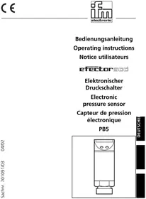
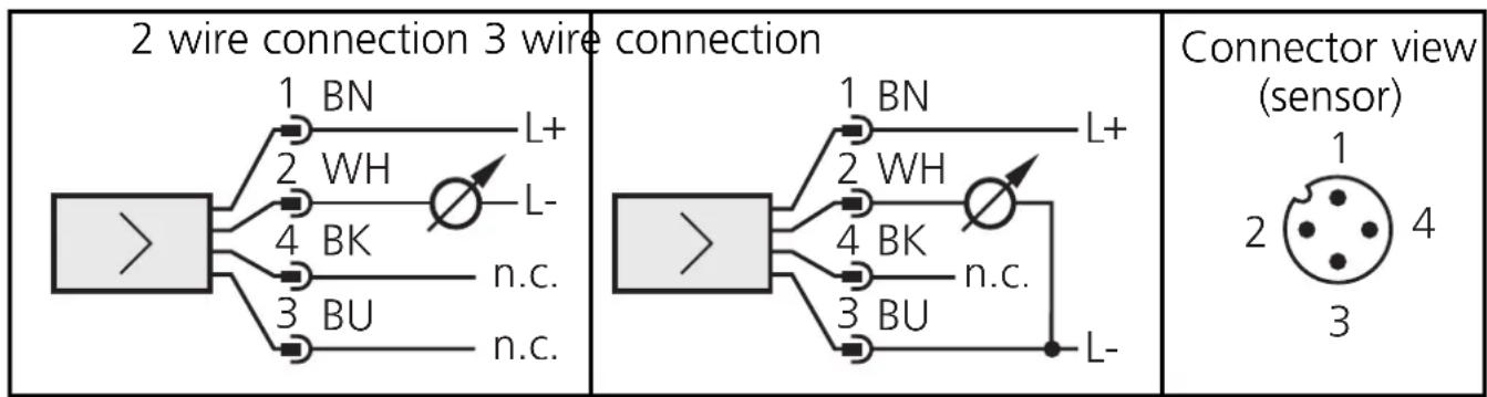
The unit is adaptable for various process fittings. ifm adapters to be ordered separately as accessories.
Mount adapter (B) to the sensor first, then sensor + adapter to the process connection by means of a nut, a clamping flange or similar (A).
If it is not possible to slide the fixing element (A) down over the top of the sensor: slide it up over the bottom of the sensor before the adapter is mounted.
Note: Sensor and adapter are only to be mounted once.
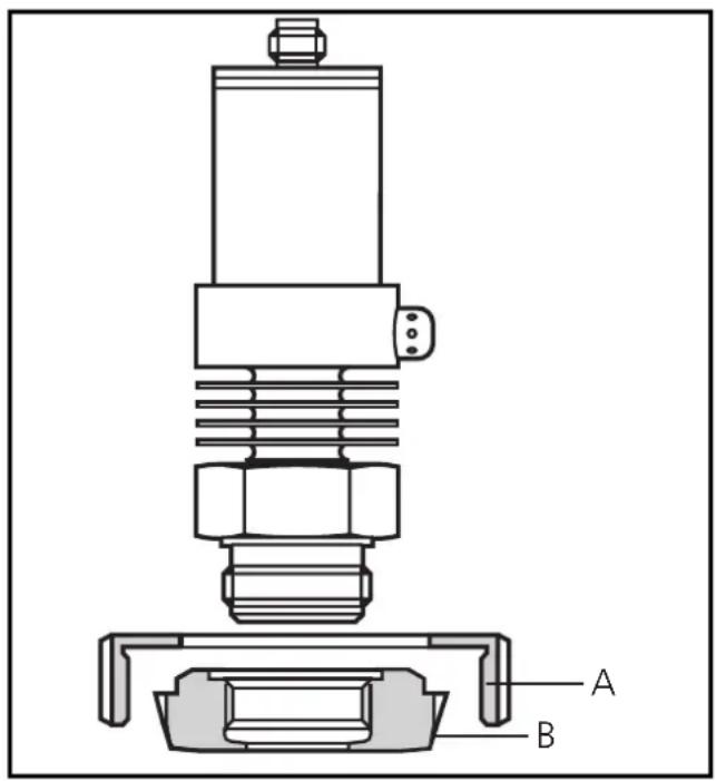
Mounting of the adapter Step 1
Grease thread and sealing chamfer of the sensor and of the adapter with the greasing paste supplied.
The greasing paste is food-grade (USDA-H1 84-201).
Make sure that the O-ring (C) is correctly positioned.
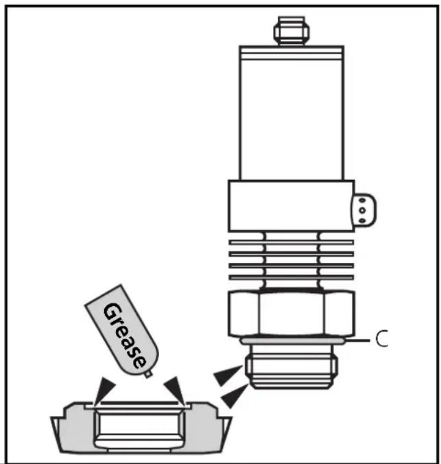
Step 2
Screw the sensor into the adapter. Avoid mechanical influence on the sealing chamfers.
Step 3
Clamp sensor and adapter into a clamping device (D). The sealing chamfers (E) must not be damaged. Tighten the sensor with a spanner until you can feel the end stop.
Note: If you continue to turn, this can have adverse effect on the sealing.
natural_image
Diagram of a mechanical device with a hand pointing to a component (no text or symbols present)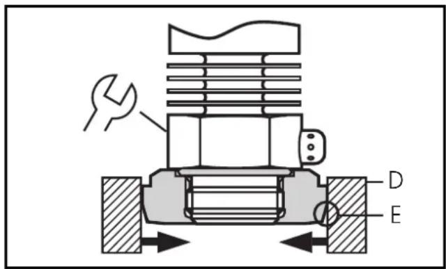
2
Electrical connection
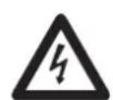
The unit must be connected by a suitably qualified electrician.
The national and international regulations for the installation of electrical equipment must be observed.
Voltage supply to EN50178, SELV, PELV.
Disconnect power before connecting the unit as follows:
ENGLISH
Core colours of ifm sockets:
1 = BN (brown), 2 = WH (white), 3 = BU (blue), 4 = BK (black);
n.c. = not connected.
2
Installation and set-up / operation / maintenance
After mounting, wiring and setting check whether the unit operates correctly.
Cleaning of the filter cover
If viscous and residues producing media clog the filter cover of the sensor (and thus reduce the measuring accuracy slightly), you can clean it.
Unscrew the filter cover (B) (use a pair of pliers with plastic-covered jaws for this). Clean the cover thoroughly.
The vent (A) should only be cleaned by skilled personnel and with utmost care.

Possible medium residues must not be compressed and pressed into the vent. This could clog the filter system and reduce the measuring accuracy of the sensor.
Screw the filter cover again tightly.
The sensor is sufficiently protected against harsh ambient conditions (protection IP 67). The protection rating can be increased by a special accessory (order no. E30043).
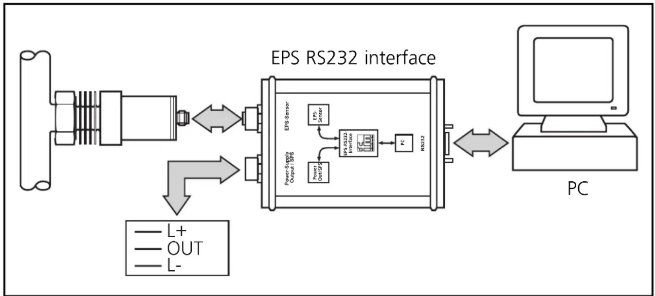
Programming / Use with EPS RS232 interface
3
flowchart
graph LR
    A["Input"] --> B["Component"]
    B --> C["EPS Sensor"]
    C --> D["Power Supply / Output / EPS"]
    D --> E["PC"]
    E --> F["Output / PS"]
    F --> G["PSRS232 Interface"]
    G --> H["PC"]
    H --> I["PC"]
    style A fill:#f9f,stroke:#333
    style I fill:#ccf,stroke:#333
Connect the sensor to a PC via the EPS-RS232 interface (order no. E30066).
- The sensor is supplied with operating voltage by the interface,
- and transmits its data (measured values, analogue signal and parameter settings) continuously via the interface.
It provides the following options:
- Remote display
Indication of the current system pressure by PC or display.
- Remote evaluation
Output of the current analogue value.
- Programming / remote programming of the sensor
Scaling the measuring range, damping for the analogue output, calibration of the sensor.
Parameters can be set before the sensor is mounted and set up or during operation.

If you change the parameters during operation, the functioning of the plant will be affected. Ensure that plant malfunction is prevented.
3
Wiring of sensor and EPS interface
For use of the sensor with EPS interface prior to installation of the sensor: Use a suitable power supply (24V power supply; ifm order no. E30080).
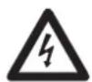
For mobile use of the interface after installation of the sensor:
Disconnect power before connecting the unit.
Do not disconnect these connections while live.
flowchart
graph TD
    A["sensor"] --> B["1"]
    A --> C["2"]
    A --> D["3"]
    A --> E["4"]
    F["L+"] --> G["BN"]
    H["L-"] --> I["WH"]
    J["n.c."] --> K["BU"]
    L["RS232"] --> M["Rx"]
    L --> N["Tx"]
    L --> O["GND 2"]
    P["Sensor"] --> Q["1"]
    P --> R["2"]
    P --> S["3"]
    P --> T["4"]
    U["Ground"] --> V["Measurement Point"]
    W["Measurement Point"] --> X["Measurement Point"]
    Y["Measurement Point"] --> Z["Measurement Point"]
Core colours of ifm sockets:
1 = BN (brown), 2 = WH (white), 3 = BU (blue), 4 = BK (black).
n.c. = not connected
Programming
A service program for the PC which is easy to use and self-explanatory (order no. E30069) is available for the programming of the sensor.
Technical information / Functioning / Parameters
4
Adjustable parameters
| ASP | Analogue start pointMeasured value at which 4mA is provided. |
| AEP | Analogue end pointMeasured value at which 20mA is provided.Minimum distance between ASP and AEP = 25% of the span.Setting range: →page 33. |
| HILO | Min-Max memory for system pressure• HI: displays the highest measured pressure.• LO: displays the lowest measured pressure. |
| COF | Calibration offsetThe internal measured value (operating value of the sensor) is offset against the real measured value.• Setting range: -5 ... +5% of the value of the span(with scaling as factory setting (ASP = 0bar and AEP = final value of measuring range),• in steps of 0.1% of the value of the span. |
| CAr | Calibration resetResets the calibration set by COF. |
| dAA | Damping for the analogue outputPressure peaks of short duration or high frequency can be filtered out.dAA-value = response time between pressure change and change of the switching status in milliseconds (ms).• setting range: 0 (= dAA is not active) / 0.1s / 0.5s / 2s. |
| Uni | Display unitThe measured values and values for ASP / AEP can be indicated in the following units:bAr (= bar / mbar), PSI, PA (= MPa / kPa).Select the display unit before setting the limits for the analogue output signal (ASP, AEP). This avoids rounding errors generated internally during the conversion of the units and enables exact setting of the limits for the analogue output signal. |
4
Adjustable parameters (continuation)
diS
Setting of the display
d1 / d2 / d3 = update of the measured value every 50ms / 200ms / 600ms. The update interval only refers to the display.
ph = display of the measured peak value remains for a short time (peak hold).
rotated = display rotated 180°.
OFF = in the Run mode the display of the measured value is deactivated.
Technical data
Operating voltage [V] 14 ... 30 DC
Operating voltage for EPS interface with sensor [V] ..... 15.5 ... 30 DC
Analogue output 4 ... 20 mA
Measuring range scaleable (turn down 1:4 of the value of the measuring range)
Max. load [Ω]: ..... (U B - 13) x 50; 550 at U B = 24V
Rise time (with damping dAA = 0) [ms] .... 3
Accuracy / deviations (in% of the span) 1)
- Characteristics deviation (linearity, incl. hysteresis and repeatability ^2) .... < ± 0.6
- repeatability (with temperature fluctuations < 10K) .... .... .... < ± 0.1
- Long-time stability (in% of the span per year) .... < ± 0.1
- Temperature coefficients (TEMPCO) in the compensated temperature range 0 ... +80°C (in% of the span per 10 K)
- greatest TEMPCO of the zero point .... < ± 0.1
Insulation resistance [MΩ]....>100 (500 V DC)
Shock resistance [g] . . . . . . . . . . . . . . . . . . 50 (DIN / IEC 68-2-27, 11ms)
Vibration resistance [g] ..... 20 (DIN / IEC 68-2-6, 10 - 2000 Hz)
Housing material .... stainless steel (316S12); PA; PBTP
Materials (wetted parts) .... stainless steel (316S12); ceramics (99.9 % Al2 O3); PTFE
^1) all indications are referred to a turn down of 1:1
^2) limit value setting to DIN 16086
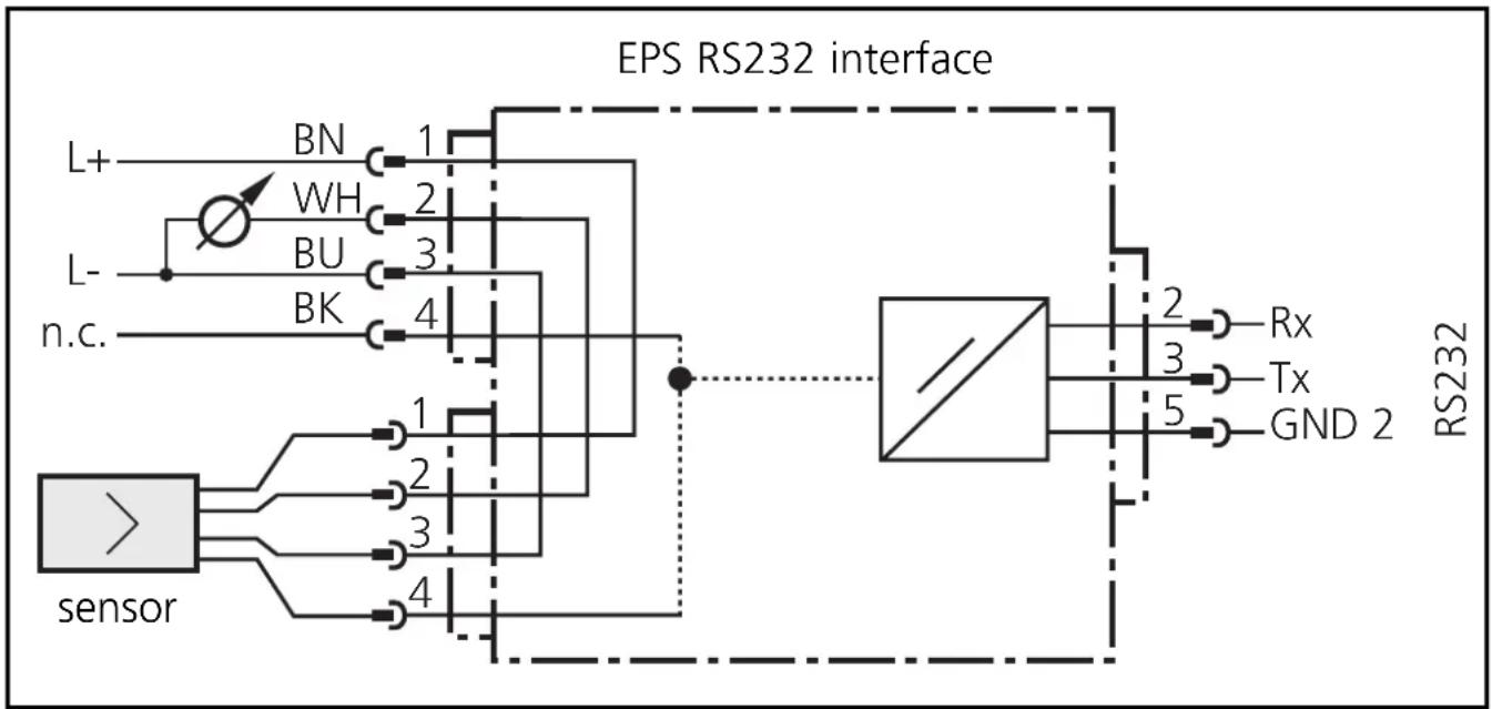
Scaling the measuring range
- With the parameter "Analogue start point" (ASP) the measured value at which the output signal is 4mA is defined.
- With the parameter "Analogue end point" (AEP) the measured value at which the output signal is 20mA is defined.
- Minimum distance between ASP and AEP = 25 % of the span (scaling factor 4).
line
Factory preset | Condition | I [mA] | | :--- | :--- | | 0 (ASP)-1 | 4 | | MEW (AEP) | 20 | | ASP-1 0AEP MEW | -20 | The chart displays two line plots representing current responses over time. The left plot is labeled 'Factory preset', the right plot is labeled 'Measuring range scaled'. Both plots share the same axes labeled 'P' but lack explicit numerical labels on the y-axis.MEW = final value of the measuring range
The output signal is between 4 and 20mA in the set measuring range. It is also indicated:
- System pressure above the measuring range: output signal > 20 mA.
- System pressure below the measuring range: output signal drops to max. 3.2mA (depending on the scaling).
Contenu
Applications (Type de pression: pression relative):
| N° de commande | Etendue de mesure | Surpression admissible | Pression d’éclatement | |
| PM2053 | bar | -1,0 ... 25 100 | 350 | |
| PSI | -15 ... 363 145 | 0 5070 | ||
| MPa | -0,1 ... 2,5 10 | 35 | ||
| PM2054 | bar | -0,5 ... 10 50 | 150 | |
| PSI | -7 ... 145 725 | 2175 | ||
| kPa | -50 ... 1000 | 5000 (5 MPa) | 15000 (15 MPa) | |
| PM2056 | bar | -0,13 ... 2,50 | 20 50 | |
| PSI | -1,8 ... 36,3 | 290 725 | ||
| kPa | -13 ... 250 | 2000 (2 MPa) | 5000 (5 MPa) | |
| PM2057 | mbar | -50 ... 1000 | 10000 (10 bar) | 30000 (30 bar) |
| PSI | -0,7 ... 14,5 | 145 450 | ||
| kPa | -5,0 ... 100 | 1000 (1 MPa) | 3000 (3 MPa) |

natural_image
Diagram of a mechanical device with a hand pointing to a component (no text or symbols present)

Tenue aux chocs [g] ..... 50 (DIN / CEI 68-2-27, 11ms)
Tenue aux vibrations [g] ..... 20 (DIN / CEI 68-2-6, 10 - 2000 Hz)
Boîtier ..... INOX 316L; PA; PBTP
① filter cover
② sealing edge
③ thread for connection to ifm process adapters