ST0512 - Flow controller IFM - Free user manual and instructions
Find the device manual for free ST0512 IFM in PDF.

| Product type | Flow controller |
| Brand | IFM |
| Model | ST0512 |
| Measurement principle | Thermal |
| Compatible fluids | Liquid fluids |
| Power supply | Up to 60 V, SELV/PELV per EN50178 |
| Electrical connection | M12x1 connector, 4 wires (BN, WH, BU, BK) |
| Output | Switching signal (on/off) |
| Display | LED bar: red (not set), yellow (output switched), green (set) |
| Adjustment | Sensitivity potentiometer |
| Process connection | T-connection per DIN 2353 |
| Dimensions (L x W x H) | 101 x 52 x 72 mm (approximate) |
| Probe diameter | 8.2 mm |
| Thread | M12x1 |
| Minimum upstream distance | 5 x pipe diameter |
| Minimum downstream distance | 3 x pipe diameter |
| Protection against interference | IEC 1000-4-2/3/4/6 (levels specified in the manual) |
| Probe material | Stainless steel |
| Maintenance | Periodic cleaning of the probe tip with a soft cloth |
| Safety | Connection by an electrician; compliance with national and international standards |
| Supplied accessories | Potentiometer protection sticker |
| Repairability | Simple user maintenance; no specific spare parts |
Frequently Asked Questions - ST0512 IFM
User questions about ST0512 IFM
0 question about this device. Answer the ones you know or ask your own.
Ask a new question about this device
Download the instructions for your Flow controller in PDF format for free! Find your manual ST0512 - IFM and take your electronic device back in hand. On this page are published all the documents necessary for the use of your device. ST0512 by IFM.
USER MANUAL ST0512 IFM
natural_image
Technical line drawing of a mechanical component with threaded end and shaft (no text or symbols)text_image
Technical diagram of a mechanical assembly with labeled parts ① and ②text_image
BN L+ BK BU L-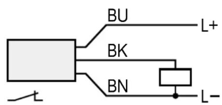
text_image
BU L+ BK BN L-text_image
1 BN 2/4 BK 3 BU L+ L-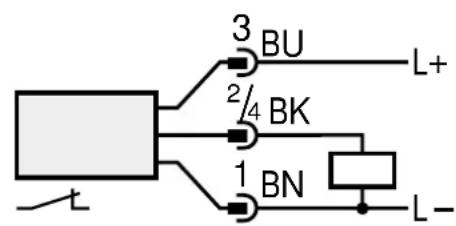
text_image
3 BU 2/4 BK 1 BN L+ L-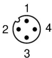
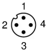
1 = BN (braun), 2 = WH (weiß), 3 = BU (blau), 4 = BK (schwarz).
Einstellen
natural_image
Diagram of a battery with internal circuit lines and terminal blocks (no text or symbols)Function and features
The flow monitor monitors liquid media. It senses whether there is a preset flow (= medium flows) or not (= medium does not flow) and provides a switching signal.
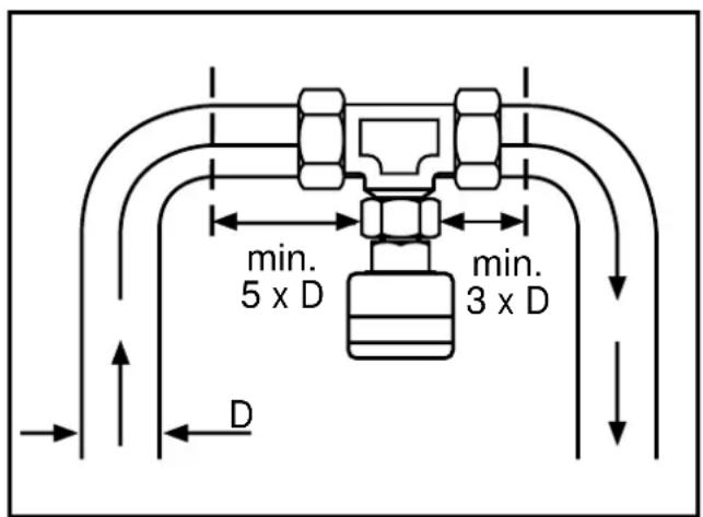
- For use in T-pieces to DIN 2353.
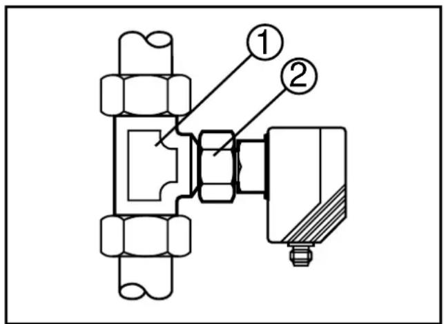
Installation
Insert the unit into the T-piece (1) and orientate it. Fasten the nut (2); always keep the unit in its orientation.
text_image
Technical diagram of a mechanical assembly with labeled parts ① and ②To avoid malfunction a minimum distance between the flow monitor and bends, valves or such like must be observed (fig. 3).
- Min. 5 x pipe diameter upstream,
- Min. 3 x pipe diameter downstream.
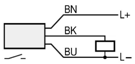
Electrical connection
The unit must only be mounted by an electrician.
The national and international regulations for the installation of electrical equipment must be observed.
Voltage supply for units up to 60 V to EN50178, SELV, PELV.
Disconnect power before connecting the unit.
Wiring diagramm:
text_image
BN L+ BK BU L-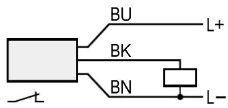
text_image
BU L+ BK BN L-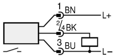
text_image
1 BN 2/4 BK 3 BU L+ L-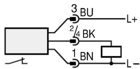
text_image
3 BU 2/4 BK 1 BN L+ L-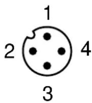
Core colours of ifm sockets:
1 = BN (brown), 2 = WH (white), 3 = BU (blue), 4 = BK (black).
Adjustment

natural_image
Diagram of a battery with an open lid and internal circuit lines (no text or symbols)setting potentiometer sensitivity

chain of LED's
- red LED lights: the unit is not adjusted
- yellow LED lights: the output is switched
-
green LED lights: the unit is adjusted
-
Apply the operating voltage. Switch on the flow (preset value) and keep it constant.
The yellow LED lights; the output is switched for about 20s (power-on delay time). - Turn the pot until one green LED comes on. The farther the green LED is away from the yellow LED, the safer is the adjustment (excess gain for flow or temperature fluctuations).
- Conceal the pot after adjustment by the label provided to protect it against unauthorised tampering.
Operation
After mounting, wiring and setting check whether the unit operates correctly.
Recommended maintenance
Check the sensor tip for build-up from time to time. Clean it with a soft cloth. If necessary, build-up which adheres firmly (e.g. lime) can be removed with a common vinegar cleansing agent.
The units are suitable for use in moderate electromagnetic fields (see table). When operating ISM equipment or powerful walkie-talkies in the vicinity of the units additional measures to avoid malfunction can be required.
| Noise immunity Standard Severity level | ||
| ESD | IEC 1000-4-2 / EN 61000-4-2 | 4 kV CD / 8 kV AD |
| HF radiated | IEC 1000-4-3 / EN 61000-4-3 | 3 V/m; 80 ... 1000 MHz |
| Burst | IEC 1000-4-4 / EN 61000-4-4 | 2 kV coupling pliers |
| HF conducted | IEC 1000-4-6 / EN 61000-4-6 | 3 V; 0.15 ... 80 MHz |
text_image
Technical diagram of a mechanical assembly with labeled parts ① and ②text_image
BN L+ BK BU L-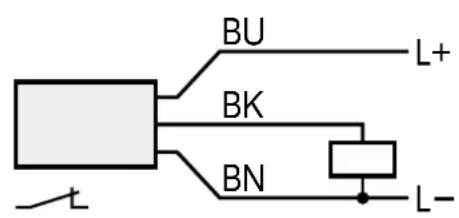
text_image
BU L+ BK BN L-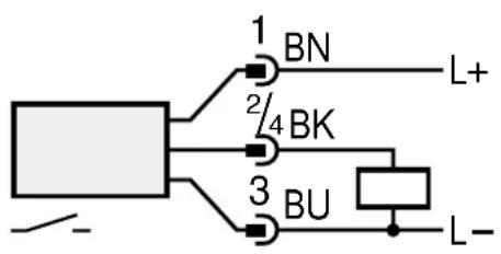
text_image
1 BN L+ 2/4 BK 3 BU L-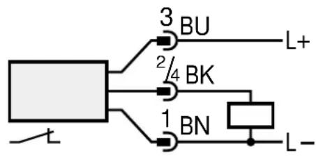
text_image
3 BU 2/4 BK 1 BN L+ L-