
ST0526 - Flow controller IFM - Free user manual and instructions
Find the device manual for free ST0526 IFM in PDF.
| Product Type | Flow Controller |
| Brand | IFM |
| Model | ST0526 |
| Dimensions | D = 15 mm for M12x1 and G1/4" thread; D = 23 mm for G1/2" thread |
| Power Supply | Up to 60 V (EN50178, SELV, PELV) |
| Main Functions | Fluid flow monitoring, rapid detection of stop or circulation (> 100 cm/s), circulation signal near switching point |
| Mounting | Probe completely immersed; horizontal pipes: lateral mounting; vertical pipes: ascending flow mounting; minimum upstream distance 5 x pipe diameter, downstream 3 x diameter |
| Electrical Connection | By electrician; disconnect power; wiring diagram with color codes (BN, WH, BU, BK) |
| Adjustment | Potentiometer; set constant flow, turn right until 6th green LED, then left until 1st/2nd green LED; 20 s delay |
| Operation | Check after configuration; faults indicated by intermittent outputs and LED oscillating between green and red |
| Maintenance and Cleaning | Check deposits on probe; clean with soft cloth; for limescale deposits, use common acetic acid product |
| Safety | Comply with national/international regulations; device for moderate electromagnetic fields; additional measures if near ISM or walkie-talkies |
| Immunity to Interference | Electrostatic discharge 4 kV CD / 8 kV AD; RF radiation 3 V/m, 80-1000 MHz; transients 2 kV; conducted RF 3 V, 0.15-80 MHz |
Frequently Asked Questions - ST0526 IFM
User questions about ST0526 IFM
0 question about this device. Answer the ones you know or ask your own.
Ask a new question about this device
Download the instructions for your Flow controller in PDF format for free! Find your manual ST0526 - IFM and take your electronic device back in hand. On this page are published all the documents necessary for the use of your device. ST0526 by IFM.
USER MANUAL ST0526 IFM
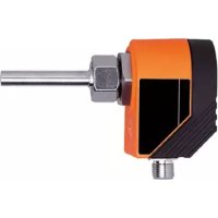
Flow monitor ST (short response time)
natural_image
Technical line drawing of a mechanical component with no visible text or symbolsFunction and features
The flow monitor monitors liquid media. It makes quick detection of flow or no flow at high flow rates possible (> 100 cm/s).
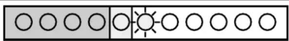
The flow signal is always near the switch point (2nd red to 2nd green LED). As a consequence the unit cannot be set with a higher excess gain in order to compensate for flow or temperature fluctuations.
The flow is to be switched on and off as quickly as possible, i.e. when the flow is switched on the maximum flow rate, when the flow is switched off the state “no flow” is to be reached as quickly as possible.
Installation
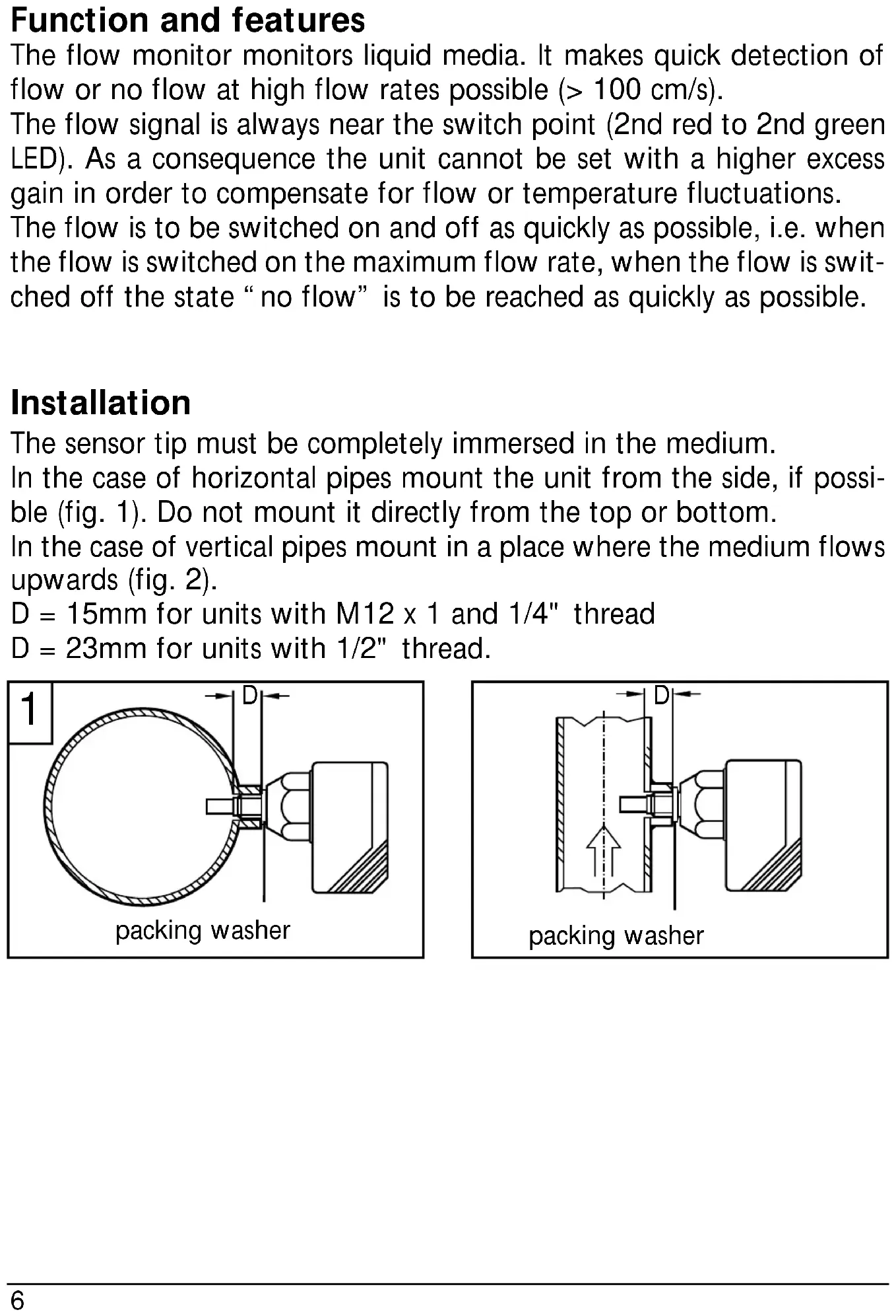
The sensor tip must be completely immersed in the medium.
In the case of horizontal pipes mount the unit from the side, if possible (fig. 1). Do not mount it directly from the top or bottom.
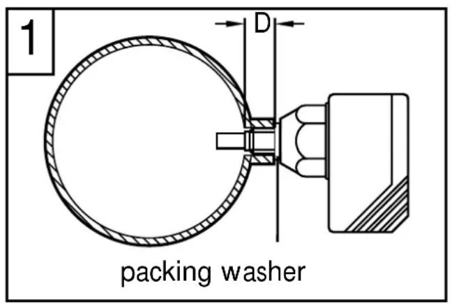
In the case of vertical pipes mount in a place where the medium flows upwards (fig. 2).
D = 15mm for units with M12 x 1 and 1/4" thread
D = 23mm for units with 1/2" thread.
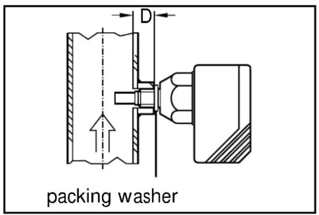
To avoid malfunction a minimum distance between the flow monitor and bends, valves or such like must be observed (fig. 3).
- Min. 5 x pipe diameter upstream,
- Min. 3 x pipe diameter downstream.
Electrical connection

The unit must only be mounted by an electrician.
The national and international regulations for the installation of electrical equipment must be observed.
Voltage supply for units up to 60 V to EN50178, SELV, PELV. Disconnect power before connecting the unit.
Wiring diagramm:

Core colours of ifm sockets:
1 = BN (brown), 2 = WH (white), 3 = BU (blue), 4 = BK (black).
Adjustment
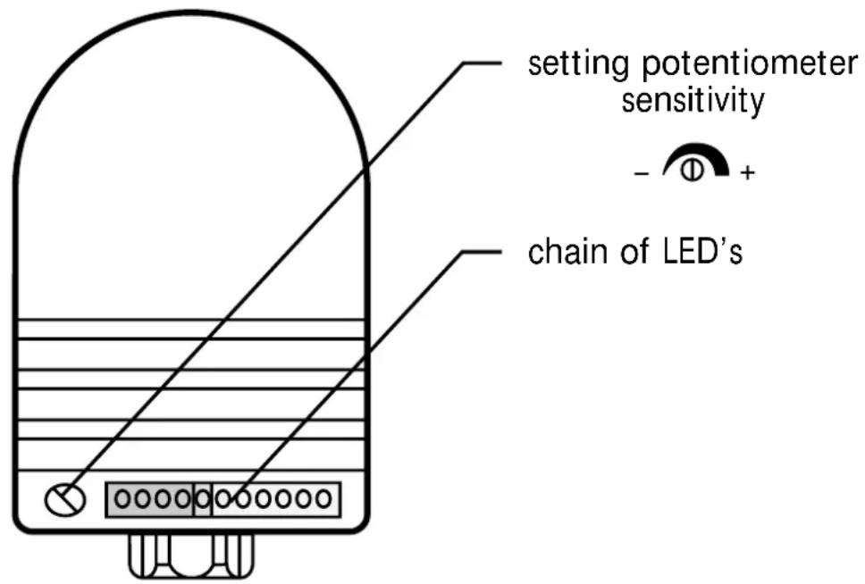
- Insert the unit into the flow and apply operating voltage.
- Set requested flow (valve "OPEN") and keep it constant.
- Set unit to 6th green LED by turning the potentiometer clockwise.

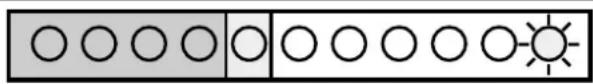
- When power-on delay time has elapsed (ca. 20s), set display to 1st/2nd green LED by turning the potentiometer anticlockwise.

- Switch off flow (valve “CLOSED”). The flow monitor indicates “no flow” after approx. 1 to 2s: the yellow LED goes off (if unit is normally open) or comes on (if unit is normally closed).
- Switch on flow again. The flow monitor indicates “flow o.k.” after 1 - 2 seconds (yellow LED comes on/goes off again).
Now the flow monitor is ready for use.
Operation
After mounting, wiring and setting check whether the unit operates correctly.
The flow monitor indicates errors by 2 signals:
a) outputs alternative: on, off, on, off,
b) the LED fluctuate from red to green and back.
The following errors are indicated in this way:
- When flow is switched on, the maximum flow rate is not reached.
- When flow is switched off, flow is not completely stopped (low flow rate remains).
- Faulty setting of the unit.
Recommended maintenance
Check the sensor tip for build-up from time to time. Clean it with a soft cloth. If necessary, build-up which adheres firmly (e.g. lime) can be removed with a common vinegar cleansing agent.
The units are suitable for use in moderate electromagnetic fields (see table). When operating ISM equipment or powerful walkie-talkies in the vicinity of the units additional measures to avoid malfunction can be required.
| Noise immunity Standard Severity level | ||
| ESD | IEC 1000-4-2 / EN 61000-4-2 | 4 kV CD / 8 kV AD |
| HF radiated | IEC 1000-4-3 / EN 61000-4-3 | 3 V/m; 80 ... 1000 MHz |
| Burst | IEC 1000-4-4 / EN 61000-4-4 | 2 kV coupling pliers |
| HF conducted | IEC 1000-4-6 / EN 61000-4-6 | 3 V; 0.15 ... 80 MHz |

Brand : IFM
Model : ST0526
Category : Flow controller