OW0005 - Temperature Controller IFM - Free user manual and instructions
Find the device manual for free OW0005 IFM in PDF.
| Product Type | Infrared Temperature Detector |
| Brand | IFM |
| Model | OW0005 (OWS/OWL series) |
| Category | Temperature Controller |
| Switching Temperature | 350 °C or 750 °C depending on variant |
| Opening Angle | 2°, 1.2°, 1° or 0.6° depending on variant |
| Max. Detection Distance | Up to 3 m (beyond that, radiation losses) |
| Power Supply | DC PNP/NPN or AC/DC (voltage not specified, typically 12-24 V) |
| Output | Switching (not short-circuit protected) |
| Connection | Wires BN (brown), BU (blue), BK (black), GN/YE (green/yellow) |
| Protection | Not specified (estimated IP65) |
| Included Accessories | Mounting base (ref. E20426) and protective sleeve (ref. E20427) optional |
| Main Functions | Contactless detection of thermal radiation, temperature threshold switching |
| Typical Use | Detection of hot objects, temperature monitoring in furnaces |
| Environmental Conditions | Dust, vapor, parasitic radiation (use protective sleeve) |
| Cleaning | Compressed air into the protective sleeve to clean the optics |
| Safety | Disconnect power before connection, use a miniature fuse, avoid short circuits |
| Maintenance | Regularly check proper operation, avoid background radiation |
| Repairability | Not repairable, replace defective device |
| Estimated Weight | Approximately 100 g |
| Estimated Dimensions | Approximately 50 x 50 x 30 mm |
Frequently Asked Questions - OW0005 IFM
User questions about OW0005 IFM
0 question about this device. Answer the ones you know or ask your own.
Ask a new question about this device
Download the instructions for your Temperature Controller in PDF format for free! Find your manual OW0005 - IFM and take your electronic device back in hand. On this page are published all the documents necessary for the use of your device. OW0005 by IFM.
USER MANUAL OW0005 IFM
natural_image
Pure technical line drawing of a mechanical component without any text, numbers, or symbolstext_image
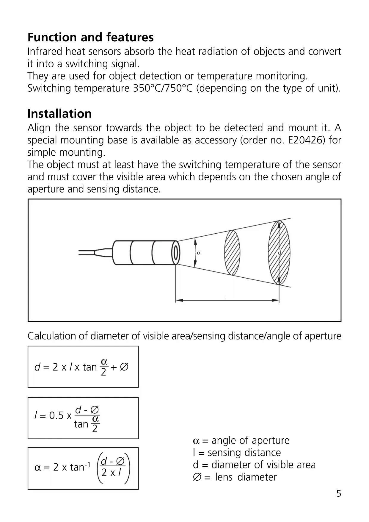
1 L+ 2 3 L-AC/DC*
flowchart
graph TD
    A["Component"] -->|1| B["L1"]
    A -->|3| C["N"]
    A -->|2| D["L-"]
    B --> E["Ground Symbol"]
    C --> F["Ground Symbol"]
    D --> G["Ground Symbol"]
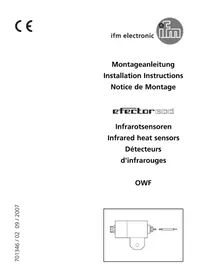
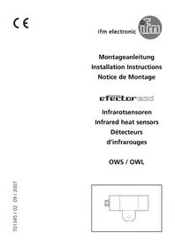
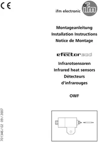
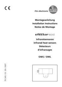
Function and features
Infrared heat sensors absorb the heat radiation of objects and convert it into a switching signal.
They are used for object detection or temperature monitoring.
Switching temperature 350^ C/ 750^ C (depending on the type of unit).
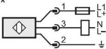
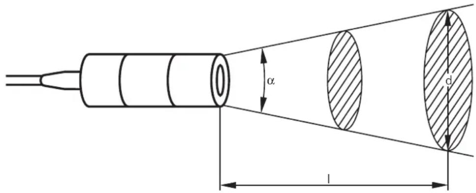
Installation
Align the sensor towards the object to be detected and mount it. A special mounting base is available as accessory (order no. E20426) for simple mounting.
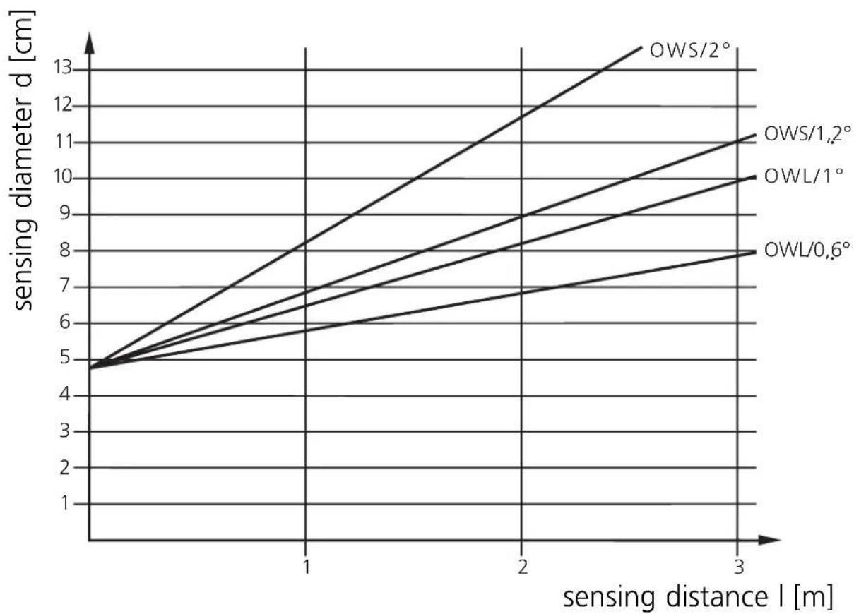
The object must at least have the switching temperature of the sensor and must cover the visible area which depends on the chosen angle of aperture and sensing distance.
text_image
α l dCalculation of diameter of visible area/sensing distance/angle of aperture
$$ d = 2 \times I \times \tan \frac {\alpha}{2} + \varnothing $$
$$ I = 0. 5 \times \frac {d - \varnothing}{\tan \frac {\alpha}{2}} $$
$$ \alpha = 2 \times \tan^ {- 1} \left(\frac {d - \emptyset}{2 \times I}\right) $$
$$ \alpha = \text { angle of aperture } $$
$$ l = \text { sensing distance } $$
$$ d = \text { diameter of visible area } $$
$$ \emptyset = \text { lens diameter } $$
Sensing range diagram:
line
| sensing distance l [m] | OWS/2° | OWS/1.2° | OWL/1° | OWL/0.6° | | ---------------------- | ------ | -------- | ------ | -------- | | 0 | 5 | 5 | 5 | 5 | | 1 | 8 | 7 | 6 | 5.5 | | 2 | 11 | 9 | 8 | 6.5 | | 3 | 13 | 11 | 10 | 7.5 |In the event of ranges of >5m radiation losses must be taken into account. The temperature of the object should therefore be much higher than the switching temperature of the sensor.
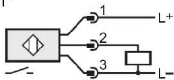
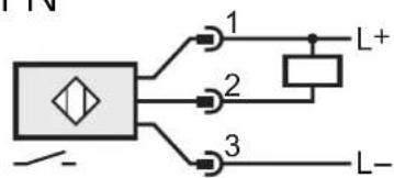
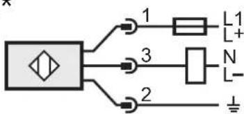
Electrical connection

Disconnect power, then connect the unit according to the wiring diagram.
DC PNP
flowchart
graph TD
    A["Input Line"] --> B["Node 1"]
    A --> C["Node 2"]
    A --> D["Node 3"]
    B --> E["L+"]
    C --> F["L-"]
    D --> G["Load Resistor"]
DC NPN
flowchart
graph TD
    A["Symbol"] --> B["1"]
    A --> C["2"]
    A --> D["3"]
    B --> E["L+"]
    C --> F["L-"]
    D --> G["L-"]
AC/DC*
text_image
1 L1 L+ 3 N L- 2 ⊥Note: insert a miniature fuse according to the technical data sheet, if specified.
Recommendation: check the unit for reliable function after a short circuit.
Core colours of ifm sockets: BN = brown, BU = blue, BK = black,
GN/YE = green/yellow.
*Output not short-circuit protected.
Short circuit can lead to immediate destruction of the unit.
Operation
Check the safe functioning of the sensor.
If in the application wrong switching occurs due to background radiation (e.g. ovens), use units with higher switching temperatures.
For applications in difficult environments (e.g. dust, vapour) or in the event of heat reflections of the environment use infrared heat sensors with a protective tube (order no. E20427).
If necessary, keep the optics clean by means of passing compressed air into the connection piece of the protective tube.