
OW5002 - Temperature Controller IFM - Free user manual and instructions
Find the device manual for free OW5002 IFM in PDF.
| Product Type | Infrared Temperature Controller |
| Brand | IFM |
| Model | OW5002 (OWF series) |
| Switching Temperature Range | 500°C / 900°C depending on device type |
| Aperture Angle | 2°, 7° or 68° depending on model |
| Max Detection Distance | 5 m (beyond, radiation losses) |
| Detection Diameter | Calculated using formula: d = 2 × l × tan(α/2) + ∅ |
| Power Supply | DC, PNP or NPN |
| Ambient Temperature (Amplifier) | max. 60 °C |
| Allowable Temperature (Fiber Optic) | max. 250 °C |
| Electrical Connection | Wires BN (brown), BU (blue), BK (black), GN/YE (green/yellow) |
| Short-Circuit Protection | No (output may be destroyed) |
| Available Accessories | Mounting base (E20426), additional lens |
| Replacement of Fiber Optic | Possible according to described procedure |
Frequently Asked Questions - OW5002 IFM
User questions about OW5002 IFM
0 question about this device. Answer the ones you know or ask your own.
Ask a new question about this device
Download the instructions for your Temperature Controller in PDF format for free! Find your manual OW5002 - IFM and take your electronic device back in hand. On this page are published all the documents necessary for the use of your device. OW5002 by IFM.
USER MANUAL OW5002 IFM
natural_image
Technical line drawing of a mechanical component with threaded fastener and shaft (no text or symbols)AC/DC*
Betrieb
Function and features
Infrared heat sensors absorb the heat radiation of objects and convert it into a switching signal.
They are used for object detection or temperature monitoring.
Switching temperature 500^ C/ 900^ C (depending on the type of unit).
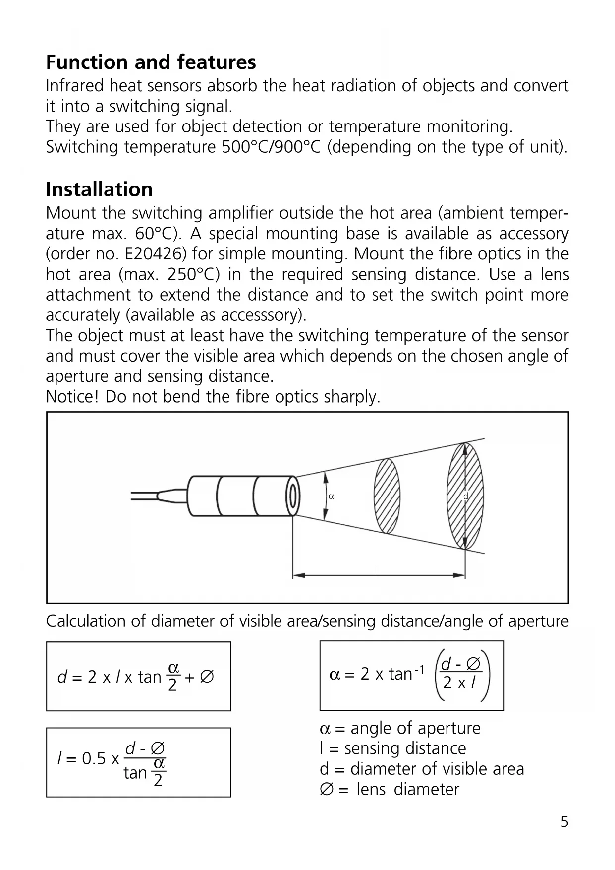
Installation
Mount the switching amplifier outside the hot area (ambient temperature max. 60°C). A special mounting base is available as accessory (order no. E20426) for simple mounting. Mount the fibre optics in the hot area (max. 250°C) in the required sensing distance. Use a lens attachment to extend the distance and to set the switch point more accurately (available as accessory).
The object must at least have the switching temperature of the sensor and must cover the visible area which depends on the chosen angle of aperture and sensing distance.
Notice! Do not bend the fibre optics sharply.
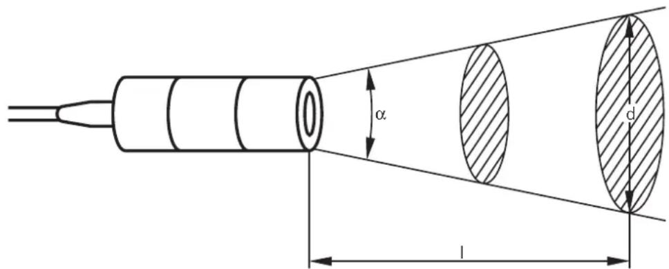
Calculation of diameter of visible area/sensing distance/angle of aperture
$$ d = 2 \times l \times \tan \frac {\alpha}{2} + \varnothing $$
$$ I = 0. 5 \times \frac {d - \varnothing}{\tan \frac {\alpha}{2}} $$
$$ \alpha = 2 \times \tan^ {- 1} \left(\frac {d - \emptyset}{2 \times I}\right) $$
α = angle of aperture
l = sensing distance
d = diameter of visible area
∅ = lens diameter
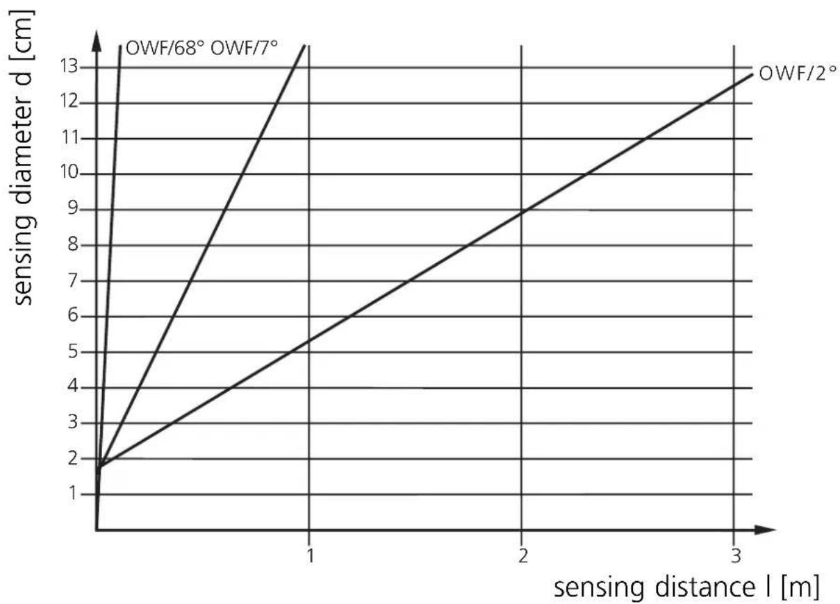
Sensing range diagram:
line
| sensing distance l [m] | OWF/68° OWF/7° | OWF/2° | | ---------------------- | -------------- | ------ | | 0 | 1 | 1 | | 1 | 13 | 5 | | 2 | - | 9 | | 3 | - | 13 |In the event of ranges of >5m radiation losses must be taken into account. The temperature of the object should therefore be much higher than the switching temperature of the sensor.
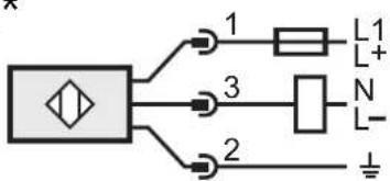
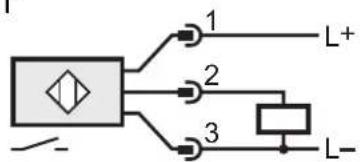
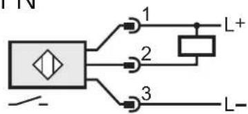
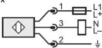
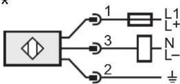
Electrical connection
Disconnect power, then connect the unit according to the wiring diagram
DC PNP
flowchart
graph TD
    A["Input"] --> B["Node 1"]
    A --> C["Node 2"]
    A --> D["Node 3"]
    B --> E["L+"]
    C --> F["L-"]
    D --> G["L-"]
DC NPN
flowchart
graph TD
    A["Symbol"] --> B["1"]
    A --> C["2"]
    A --> D["3"]
    B --> E["L+"]
    C --> F["L-"]
    D --> G["L-"]
AC/DC*
flowchart
graph TD
    A["Diamond Symbol"] --> B["1"]
    A --> C["2"]
    A --> D["3"]
    B --> E["L1 L+"]
    C --> F["N L-"]
    D --> G["⊥"]
Note: insert a miniature fuse according to the technical data sheet, if specified. Recommendation: check the unit for reliable function after a short circuit Core colours of ifm sockets: BN = brown, BU = blue, BK = black, GN/YE = green/yellow.
*Output not short-circuit protected.
Short circuit can lead to immediate destruction of the unit.
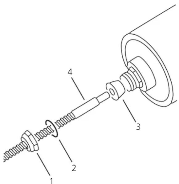
Replacement of fibre optics
Remove the nut 1 and washer 2.
Carefully remove the rubber packing 3 from the connection piece.
Remove the faulty fibre optics 4.
Slide the supplied new nut 1, washer 2, packing 3 onto the replacement fibre optics.
Insert the replacement fibre optics until the end into the hole of the switching amplifier provided for this.
Press the packing 3 into the connection piece.
Secure the replacement fibre optics by tightening the nut 1.
Operation
Check the safe functioning of the sensor.
If in the application wrong switching occurs due to background radiation (e.g. ovens), use units with higher switching temperatures.
AC/DC*
flowchart
graph TD
    A["Component"] -->|1| B["L1"]
    A -->|3| C["N"]
    A -->|2| D["L-"]
    B --> E["Ground"]
    C --> F["Ground"]
Fonctionnement

Brand : IFM
Model : OW5002
Category : Temperature Controller