RU1189 - Digital decoder IFM - Free user manual and instructions
Find the device manual for free RU1189 IFM in PDF.


| Product type | Incremental rotary encoder |
| Brand | IFM |
| Model | RU1189 |
| Power supply | 5 V TTL or 10…30 V HTL depending on version |
| Output signals | A, B (phase-shifted by 90°) and zero index, with inverted signals available |
| Output protection | 5 V version: short-circuit to 0 V; HTL version: short-circuit to 0 V and L+ (max. 1 min) |
| Maximum cable length | 100 m (5 V TTL) / 300 m (10…30 V HTL) |
| Connector type | Male base ifm1000.xx / ifm1001.xx (5-pole), cable 5 or 13 wires |
| Main functions | Measurement of linear and angular displacements, position determination |
| Mounting | On mounting flange; use a flexible coupling to compensate for misalignment |
| Maintenance | Avoid shocks to the shaft; do not use abrasive tools |
| Cleaning | Clean with a dry cloth; do not use aggressive solvents |
| Safety | Disconnect power before any connection; insulate unused wires |
| Spare parts | Connection cables, connectors, mounting flange E60033 |
| Accessories | Mounting flange E60033, flexible couplings, measuring wheel |
| Repairability | Repair by manufacturer or authorized service; no user-serviceable parts |
| General information | Manual available online; datasheet and accessories at www.ifm.com |
Frequently Asked Questions - RU1189 IFM
User questions about RU1189 IFM
0 question about this device. Answer the ones you know or ask your own.
Ask a new question about this device
Download the instructions for your Digital decoder in PDF format for free! Find your manual RU1189 - IFM and take your electronic device back in hand. On this page are published all the documents necessary for the use of your device. RU1189 by IFM.
USER MANUAL RU1189 IFM
Function and features
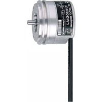
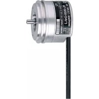
The encoder transforms rotational movement into pulse sequences. These allow the measurement of linear distances and angular movement as well as the determination of positions.
Electrical connection

Disconnect power from the installation before connecting or disconnecting cables or connectors!
Unused wires must be insulated to avoid short circuits and cross faults.
Short-circuit protection
5 V TTL version: outputs short-circuit protected against 0 V 10...30 V HTL version: outputs short-circuit protected against 0 V and L+ for maximum 1 minute
Standard wiring:
| Flange plug ifm1000.xx ifm1001.xx5-pole | |||
| L+ 2 9 12 | |||
| L+ sensor - 5 2 | |||
| 0V 1 12 10 | |||
| 0V sensor - | 10 11 | ||
| A | 3 | 1 | 5 |
| A neg. | - 2 6 | ||
| B | 4 | 3 | 8 |
| B neg. | - 4 1 | ||
| 0 index | 5 6 3 | ||
| 0 index neg. | - 7 4 | ||
| fault neg. | - | - | 7 |
| free | - | - | 9 |
| free | - | - | - |
| screen | housing | 11 | housing |
| ifm1013.xx 5-wire cable 13-wire cable | |||
| L+ 1 brown brown/green | n/green | ||
| L+ sensor - - blue | green | ||
| 0V 6 grey white/green | green | ||
| 0V sensor - - white | green | ||
| A 2 | green | brown | |
| A neg. | - - green | ||
| B | 4 | white | grey |
| B neg. | - - pink | ||
| 0 index | 5 | yellow | red |
| 0 index neg. | - - black | ||
| fault neg. | - - | lilac | |
| free | - - | - | |
| free | - - | yellow | |
| screen | 3 | housing | housing |
Wiring is also indicated on the housing cap. If there is a deviation, the encoder must be connected as indicated on the label on the housing cap.
The wires L + (sensor) and 0V (sensor) are internally connected to the supply voltage. When using external electronics which regulate the supply voltage these wires can be used as test wires. If unused, these wires must be connected to the supply voltage or insulated.
Depending on the version, the electrical connection is made via the cable or via cables to be obtained separately.
When using suitable cables the maximum cable length is 100m for the 5 V TTL version and 300m for the 10...30 V HTL version.
The cables must be laid separately from interfering sources, the minimum distance is 20~cm .
The braided screen in the cable is connected to the encoder housing.
Output signals
output A
output B
0 index
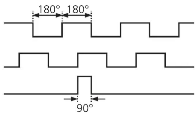
The encoder provides digital pulse sequences at the output stages. The outputs A and B are electrically offset by 90^ . Thus the direction of rotation can be evaluated in the external electronics.
The combined zero index is provided once in a mechanical revolution of the shaft. In case of power failure it can be used as a reference point within a revolution.
The inverted output signals are used for external electronics with differential voltage input to filter interference.
Installation

Do not hit the shaft, do not use a file or similar tool on the shaft: This could destroy the unit!
The encoder can be screwed to the angle bracket. The shaft should be connected using a flexible bellows or spring disc coupling to compensate for shaft displacement and to protect the encoder against damage.
Linear movements can be transformed into a rotational movement using a measuring wheel or rack and pinion. For mounting the maximum permissible shaft loads of the encoder must be taken into account.
Mounting the angle bracket on a resilient base protects the encoder against too high a stress due to roughness of the material.
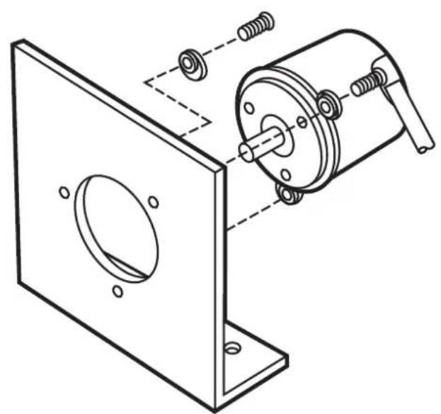
angle bracket E60033
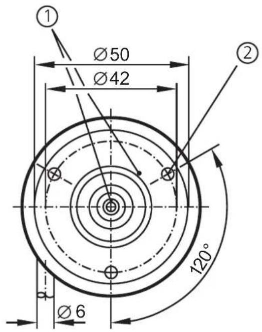
1) reference mark
2) M4 thread / 5mm deep
The data sheet, further documents and suitable accessories are available on our website at www.ifm.com.
Holder of Certificate: ifm electronic gmbh
Friedrichstr. 1
45128 Essen
GERMANY
Production
20196
Facility(ies):
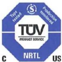
Certification Mark:
Product:
Electronic measuring equipment (encoders)
Model(s):
RAX, ROx, RPx, RBx, RCx, RUX, RVx, RSx, RMs, RNx "x" can be any character (up to 15 digits) and defines configurations, interface, resolution and length.
Parameters:
Rated Voltage: 5-30 Vdc
Rated Current: max. 370 mA
Remark:
When installing, requirements of mentioned Test
Standards and Installation Guide has to be fulfilled.
Supply shall fulfil requirements of limited energy
circuit or Class 2 power.
Tested
UL 61010-1:2004
according to:
CAN/CSA-C22.2 No.61010-1:2004
The product was voluntarily tested according to the relevant safety requirements and mentioned properties. It can be marked with the certification mark shown above. The certification mark must not be altered in any way. This product certification system operated by TÜV SÜD America Inc. most closely resembles that described by ISO/IEC Guide 67, Conformity assessment - Fundamentals of product certification, System 3. See also notes overleaf.
Test report no.:
028-71370093-000
Date, 2010-08-18
Page 1 of 1

TUV SUD AMERICA INC. 10 Centennial Drive Peabody MA 01960 USA www.TUVamerica.com

Brand : IFM
Model : RU1189
Category : Digital decoder