
TN7430 - Temperature Controller IFM - Free user manual and instructions
Find the device manual for free TN7430 IFM in PDF.
| Product type | Electronic temperature controller (temperature sensor) |
| Brand | IFM |
| Model | TN7430 |
| Measuring range | -40 to +125 °C (-40 to +257 °F) |
| Accuracy (switching output) | ± (PT1000 + 0.2 K) |
| Resolution | 0.5 °C / 1 °F (output), 0.5 °C / 0.5 °F (display) |
| Display | Digital 4-digit, switchable °C/°F, 180° orientation |
| Outputs | 2 transistor outputs (N.O./N.C.), hysteresis or window function |
| Max. output current | 250 mA |
| Supply voltage | 18-30 V DC |
| Power consumption | < 50 mA |
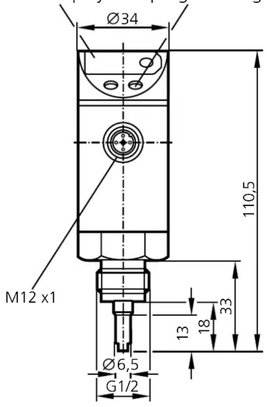
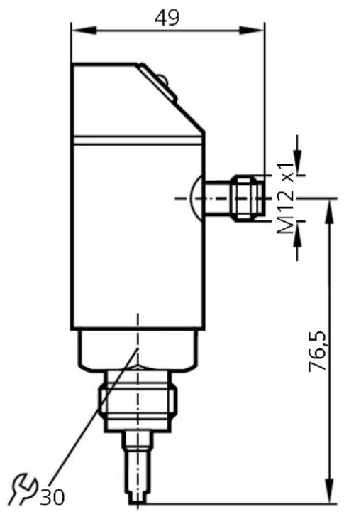
| Dimensions | Length 110.5 mm, diameter 34 mm; thread G1/2, M12 connector |
| Weight | Approx. 150 g |
| Protection rating | IP 67, class III |
| Ambient temperature | -25 to +70 °C |
| Storage temperature | -40 to +100 °C |
| Housing material | Stainless steel 304, PBTP, PC, EPDM/X, FPM (Viton) |
| Main functions | Temperature measurement, display, 2 programmable outputs (hysteresis/window), calibration, min/max memory |
| Maintenance and cleaning | No maintenance required; clean with a dry cloth |
| Safety | Short-circuit, reverse polarity, overload protection; installation by electrician |
| Spare parts and repairability | Device not repairable; must be replaced if defective |
| General information | EMC approvals according to IEC 1000-4; integrated watchdog; start-up delay 1.5 s |
Frequently Asked Questions - TN7430 IFM
User questions about TN7430 IFM
0 question about this device. Answer the ones you know or ask your own.
Ask a new question about this device
Download the instructions for your Temperature Controller in PDF format for free! Find your manual TN7430 - IFM and take your electronic device back in hand. On this page are published all the documents necessary for the use of your device. TN7430 by IFM.
USER MANUAL TN7430 IFM
natural_image
Line drawing of a handheld industrial device with a digital display and central button (no text or symbols)(M) = Mode/Enter
⑤ = Set
line
| t | T | rP | | ---- | ----- | ---- | | 0 | 0 | 0 | | 1 | 1 | 0 | | 2 | 2 | 0 | | 3 | 3 | 0 | | 4 | 4 | 0 | | 5 | 5 | 0 | | 6 | 6 | 0 | | 7 | 7 | 0 | | 8 | 8 | 0 | | 9 | 9 | 0 | | 10 | 10 | 0 | | 11 | 11 | 0 | | 12 | 12 | 0 | | 13 | 13 | 0 | | 14 | 14 | 0 | | 15 | 15 | 0 | | 16 | 16 | 0 | | 17 | 17 | 0 | | 18 | 18 | 0 | | 19 | 19 | 0 | | 20 | 20 | 0 | | 21 | 21 | 0 | | 22 | 22 | 0 | | 23 | 23 | 0 | | 24 | 24 | 0 | | 25 | 25 | 0 | | 26 | 26 | 0 | | 27 | 27 | 0 | | 28 | 28 | 0 | | 29 | 29 | 0 | | 30 | 30 | 0 | | 31 | 31 | 0 | | 32 | 32 | 0 | | 33 | 33 | 0 | | 34 | 34 | 0 | | 35 | 35 | 0 | | 36 | 36 | 0 | | 37 | 37 | 0 | | 38 | 38 | 0 | | 39 | 39 | 0 | | 40 | 40 | 0 | | 41 | 41 | 0 | | 42 | 42 | 0 | | 43 | 43 | 0 | | 44 | 44 | 0 | | 45 | 45 | 0 | | 46 | 46 | 0 | | 47 | 47 | 0 | | 48 | 48 | 0 | | 49 | 49 | 0 | | 50 | 50 | 0 | | 51 | 51 | 0 | | 52 | 52 | 0 | | 53 | 53 | 0 | | 54 | 54 | 0 | | 55 | 55 | 0 | | 56 | 56 | 0 | | 57 | 57 | 0 | | 58 | 58 | 0 | | 59 | 59 | 0 | | 60 | 60 | 0 | | Note: The data is extracted from the code and presented in CSV format as requested. The code does not include the original data points. The values for 'SP' and 'rP' are estimated based on the given code. There is only one data series in this case. The output of 'Fno' and 'Fnc' is not included in the plot area. There is no additional data series present in the image.3 = BU (blau), 4 = BK (schwarz)
OUT1 = Hno, OUT2 = Hnc,
SP1 = SP2 / rP1 = rP2.
6. Programmieren
Controls and visual indication
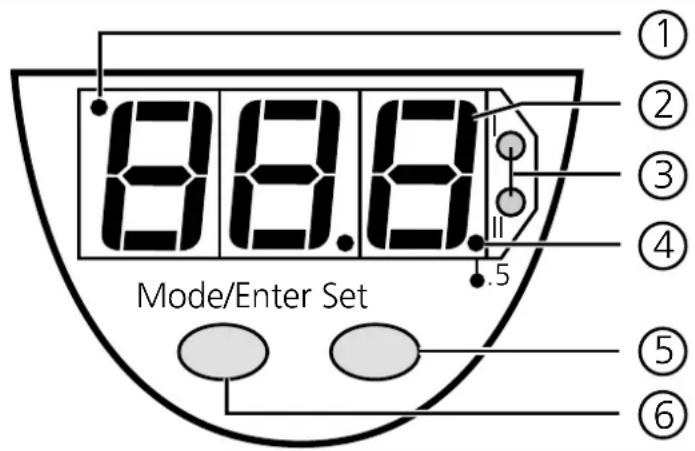
| 1 | Indicator for display unit | OFF = indication in °C;ON = indication in °F |
| 2 | 7-segment display | display of the system temperature,display of parameters and parameter values |
| 3 | 2 x LED red | switching status;lights if output I / II has switched |
| 4 | LED red LED | ON = displayed temperature + 0.5° |
| 5 | Set button | setting of the parameter values (scrolling by holding pressed; incremental by pressing briefly) |
| 6 | Mode / Enter button | selection of the parameters and acknowledgement of the parameter values |
1. Functions and features
- The temperature sensor detects the current system temperature,
• shows the current system temperature on its display (in °C or °F), - and generates 2 output signals according to the set output configuration.
| output 1 output 2 | |
| Switching function (can be selected for each output separately) | hysteresis function / N.O. (Hno) |
| hysteresis function / N.C. (Hnc) | |
| window function / N.O. (Fno) | |
| window function / N.C. (Fnc) |
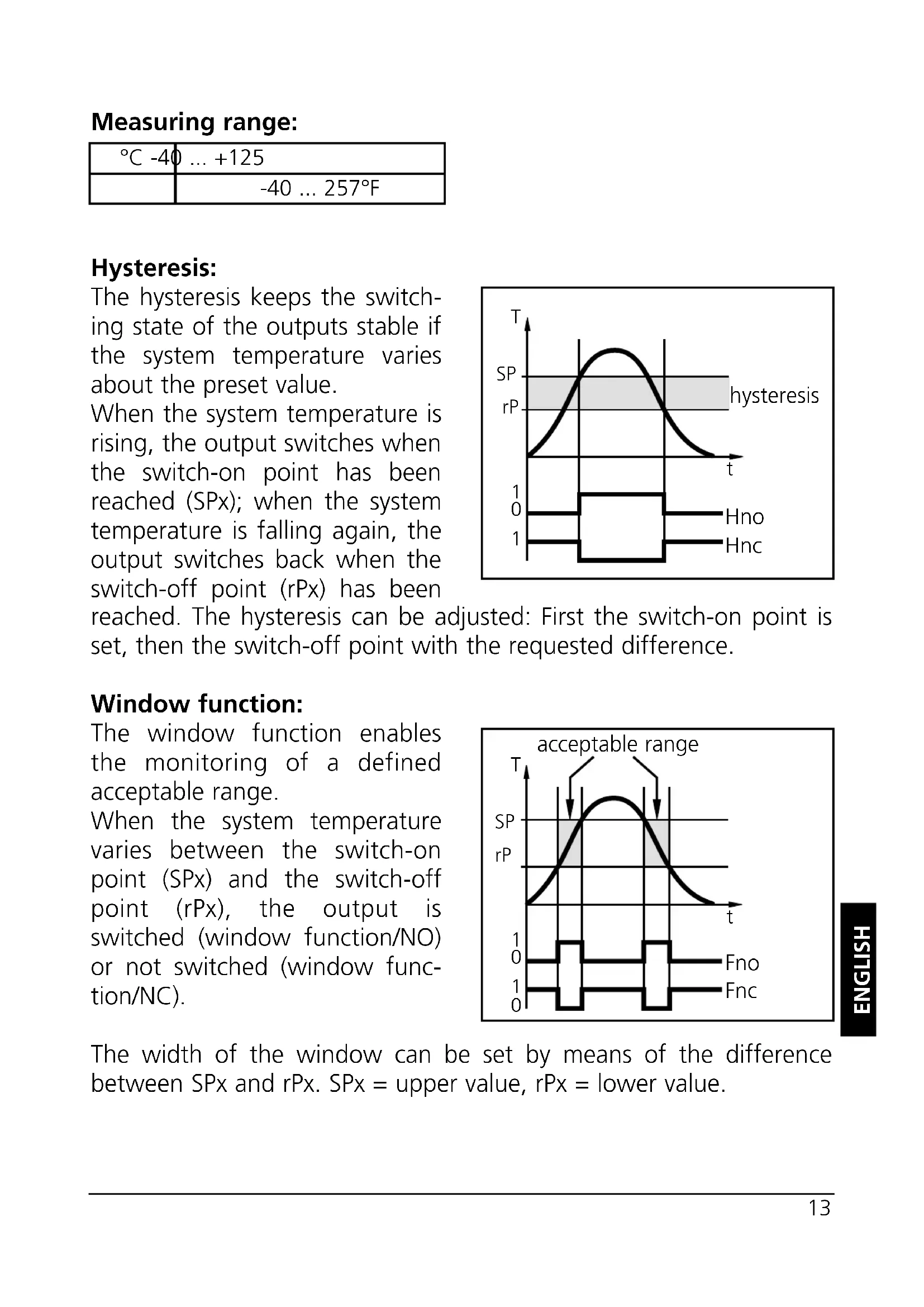
Measuring range:
| °C -40 ... +125 | |
| -40 ... 257°F | |
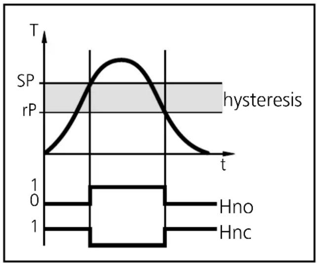
Hysteresis:
The hysteresis keeps the switching state of the outputs stable if the system temperature varies about the preset value.
When the system temperature is rising, the output switches when the switch-on point has been reached (SPx); when the system temperature is falling again, the output switches back when the switch-off point (rPx) has been reached. The hysteresis can be adjusted: First the switch-on point is set, then the switch-off point with the requested difference.
line
| t | T | |-------|-------| | Low | 0 | | Mid | Peak | | High | 0 |Window function:
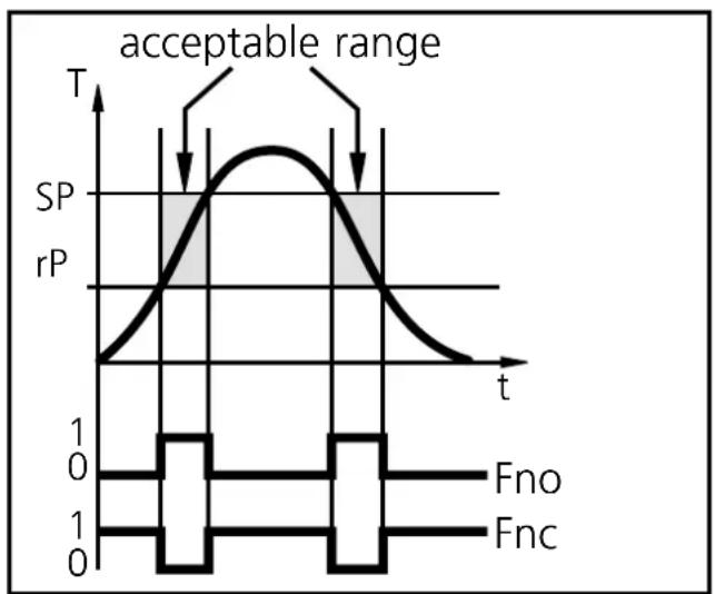
The window function enables the monitoring of a defined acceptable range.
When the system temperature varies between the switch-on point (SPx) and the switch-off point (rPx), the output is switched (window function/NO) or not switched (window function/NC).
line
| t | T | rP | | ---- | ----- | ---- | | 0 | 0 | 0 | | 1 | 1 | 0 | | 2 | 0 | 0 | | 3 | 0 | 0 | | 4 | 0 | 0 | | 5 | 0 | 0 | | 6 | 0 | 0 | | 7 | 0 | 0 | | 8 | 0 | 0 | | 9 | 0 | 0 | | 10 | 0 | 0 |The width of the window can be set by means of the difference between SPx and rPx. SPx = upper value, rPx = lower value.
2. Operating modes
Run mode:
(Normal operating mode)
When the supply voltage has been applied, the unit is in the Run mode. It monitors and switches the transistor outputs according to the set parameters..
The LED display indicates the current system temperature, the red LEDs indicate the switching state of the transistor outputs.
Display mode:
(Indication of parameters and the set parameter values)
When the "Mode/Enter" button is pressed briefly, the unit passes to the Display mode which allows parameter values to be read. The internal sensing, processing and output functions of the unit continue as if in Run mode.
- The parameter names are scrolled with each press of the "Mode/Enter" button.
- When the "Set" button is pressed briefly, the corresponding parameter value is displayed for 5s. After another 5s the unit returns to the Run mode.
Programming mode:
(Setting of the parameter values)
The unit passes to the programming mode when after the selection of a parameter value (Display mode) the "Set" button is pressed until the display of the parameter value is changed. Internally the unit remains in the operating mode. It continues its monitoring function with the existing parameters until the change has been terminated.
You can change the parameter value by pressing the "Set" button and confirm it by pressing the "Mode/Enter" button. The unit returns to the Run mode when no button has been pressed for 5s.
3. Adjustable parameters
(menu structure: see fold out page)
| SP1SP2 | Switch-on point: Upper limit value at which the output changes its switching status. | ||
| setting range in steps of | |||
| °C | -39.5 ... +125 0.5 | ||
| -39 ... +257 1°F | |||
| rP1rP2 | Switch-off point: Lower limit value at which the output changes its switching status. | ||
| setting range in steps of | |||
| °C | -40 ... +124.5 0.5 | ||
| -40 ... +256 1°F | |||
| rPx is always lower than SPx. The unit only accepts values which are lower than SPx.Changing the switch-on point also changes the switch-off point (the hysteresis remains constant).If the hysteresis is higher than the new switch point, it is automatically reduced (rPx is set to the minimum setting value). | |||
| OU1OU2 | Configuration of the switching outputs4 switching functions can be set:Hno = hysteresis / normally openHnc = hysteresis / normally closedFno = window function / normally openFnc = window function / normally closed | ||
| d15 | Setting of the display4 options can be selected:°C = display in °Celsius°F = display in °Fahrenheitr°C = display in °Celsius (inverted)r°F = display in °Fahrenheit (inverted) | ||
| CAL | Calibration offsetThe internal measured value (operating value of the sensor) is offset against the real measured value. | ||
| setting range in steps of | |||
| °C | -9.9 ... +9.9 0.1 | ||
| -17.5 ... +17.5 0.5°F | |||
| HILo | Min-Max memory for system temperatureHi: displays the highest measured temperatureLo: displays the lowest measured temperatureErase the memory:- Press the "Mode/Enter" button until HI or Lo is displayed.- Press the "Set" button and keep it pressed until “- - -” is displayed.- Then press the "Mode/Enter" button briefly.It is recommended to erase the memory as soon as the unit starts working under normal operating conditions. |
4. Installation
Mount the temperature sensor to the G ^1/2 process connection.
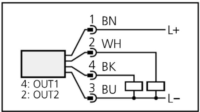
5. Electrical connection

The unit must only be connected by an electrician.
The national and international regulations for the installation of electrical equipment must be observed.
Voltage supply to EN50178, SELV, PELV.
Disconnect power before connecting the unit. Wiring:
flowchart
graph TD
    A["4: OUT1\n2: OUT2"] --> B["1: BN"]
    A --> C["2: WH"]
    A --> D["3: BU"]
    A --> E["4: BK"]
    B --> F["L+"]
    C --> G["BK"]
    D --> H["BU"]
    E --> I["L-"]
Core colours of ifm sockets:
1 = BN (brown), 2 = WH (white)
3 = BU (blue), 4 = BK (black)
Programming of complementary outputs:
output 1: = Hno, output 2: = Hnc,
SP1 = SP2 / rP1 = rP2.
6. Programming
| 1 | 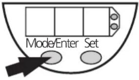 | 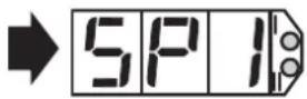 | Press the Mode/Enter button several times until the respective parameter is displayed. |
| 2 | 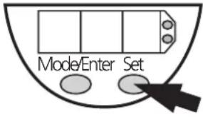 | 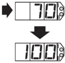 | Press the Set button and keep it pressed. The current parameter value is indicated for 5s, then the value is increased* (incremental by pressing briefly or scrolling by holding pressed). |
| 3 | 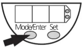 | 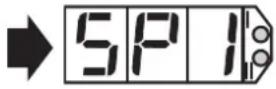 | Press the Mode/Enter button briefly (= acknowledgement). The parameter is displayed again, the set parameter value becomes effective. |
| Wait 5s (the unit passes to the operating mode and the current measured value is indicated again), or start again with step 1 to program other parameters. | |||
*Decrease the value: Let the display of the parameter value move to the maximum setting value. Then the cycle starts again at the minimum setting value.
Locking / unlocking:
The unit can be electronically locked to prevent unwanted adjustment of the set parameters: Press (in Run mode) both pushbuttons for 10s. As soon as the indication goes out the unit is locked or unlocked. Units are delivered from the factory in the unlocked state.
7. Installation and set-up / operation
Check the safe functioning of the unit. The operation is maintenance-free. Failure indication:
| OL | = too high a temperature |
| UL | = too low a temperature |
| SC1 | (flashing) = short-circuit in switching output 1/2; |
| SC2 | the respective output is switched off. |
8. Scale drawing
7-segment display programming button
9. Technical data
| Operating voltage [V]....18 ... 30 DCCurrent rating [mA].....250Short-circuit protection,Reverse polarity protection / overload protection,Integrated WatchdogVoltage drop [V].....< 2Current consumption [mA]....< 50 |
| Measuring element....1 x PT 1000 to DIN EN 60751, class BAccuracySwitching output....± (PT 1000 + 0.2 K)Display....± (PT 1000 + 0.2 K + 1⁄2 digit)ResolutionSwitching output [°C/°F]....0.5 / 1Display [°C/°F]....0.5 / 0.5Temperature drift [% of value of measuring range/10 K]....± 0.1 |
| Measuring / display cycle [ms]....200Power-on delay time [s]....1.5 |
| Housing material....stainless steel (304S15); Pocan; PC (Macrolon);EPDM/X (Santoprene); FPM (Viton)Materials (wetted parts)....stainless steel (303S22)Operating temperature [°C]....-25 ... +70Storage temperature [°C]....-40 ... +100Protection....IP 67, IIIInsulation resistance [MΩ]....>100 (500 V DC)Shock resistance [g]....50 (DIN / IEC 68-2-27, 11ms)Vibration resistance [g]....20 (DIN / IEC 68-2-6, 10 - 2000 Hz)EMCIEC 1000/4/2 ESD:....4 / 8 KVIEC 1000/4/3 HF radiated:....10 V/mIEC 1000/4/4 Burst:....2 KVIEC 1000/4/6 HF conducted:....10 V |
line
| t | T | rP | | ---- | ----- | ---- | | 0 | 0 | 0 | | 1 | 1 | 1 | | 2 | 0 | 0 | | 3 | 0 | 0 | | 4 | 0 | 0 | | 5 | 0 | 0 | | 6 | 0 | 0 | | 7 | 0 | 0 | | 8 | 0 | 0 | | 9 | 0 | 0 | | 10 | 0 | 0 | | 11 | 0 | 0 | | 12 | 0 | 0 | | 13 | 0 | 0 | | 14 | 0 | 0 | | 15 | 0 | 0 | | 16 | 0 | 0 | | 17 | 0 | 0 | | 18 | 0 | 0 | | 19 | 0 | 0 | | 20 | 0 | 0 | | 21 | 0 | 0 | | 22 | 0 | 0 | | 23 | 0 | 0 | | 24 | 0 | 0 | | 25 | 0 | 0 | | 26 | 0 | 0 | | 27 | 0 | 0 | | 28 | 0 | 0 | | 29 | 0 | 0 | | 30 | 0 | 0 | | 31 | 0 | 0 | | 32 | 0 | 0 | | 33 | 0 | 0 | | 34 | 0 | 0 | | 35 | 0 | 0 | | 36 | 0 | 0 | | 37 | 0 | 0 | | 38 | 0 | 0 | | 39 | 0 | 0 | | 40 | 0 | 0 | | 41 | 0 | 0 | | 42 | 0 | 0 | | 43 | 0 | 0 | | 44 | 0 | 0 | | 45 | 0 | 0 | | 46 | 0 | 0 | | 47 | 0 | 0 | | 48 | 0 | 0 | | 49 | 0 | 0 | | 50 | 0 | 0 | | 51 | 0 | 0 | | 52 | 0 | 0 | | 53 | 0 | 0 | | 54 | 0 | 0 | | 55 | 0 | 0 | | 56 | 0 | 0 | | 57 | 0 | 0 | | 58 | 0 | 0 | | 59 | 0 | 0 | | 60 | 0 | 0 | | Note: The actual values for T and rP are not provided in the code. The code does not provide a valid representation of the plot. The labels 'plage acceptable' and 'Fno/Fnc' appear above the plot area.1 = BN (brun), 2 = WH (blanc)
3 = BU (bleu), 4 = BK (noir)

- Programmieren
- Controls and visual indication
- Functions and features
- Measuring range:
- Hysteresis:
- Window function:
- Operating modes
- Run mode:
- Display mode:
- Programming mode:
- Adjustable parameters
- Installation
- Electrical connection
- Programming
- Locking / unlocking:
- Installation and set-up / operation
- Scale drawing
- Technical data
Brand : IFM
Model : TN7430
Category : Temperature Controller