
AC2463 - Electronic module IFM - Free user manual and instructions
Find the device manual for free AC2463 IFM in PDF.

| Product Type | AS-interface electronic module |
| Brand | IFM |
| Model | AC2463 |
| AS-interface version | 2.1 |
| Profile | S-0.1.E |
| Maximum number of modules per master | 31 |
| Address range | 1 to 31 (default address: 0 for slave 1, 31 for slave 2) |
| Addressing | Via AC1144 addressing unit (cable E70123 or E70211) or infrared |
| Power supply | Supply class 2 according to cULus (standard AS-i voltage) |
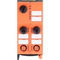
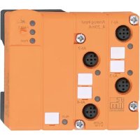
| Input connections | M12 connector, 4 inputs (D0-D3) on connectors I-1/2, I-2, I-3/4, I-4 |
| LED display | LED 1 yellow: input switched; LED 2 green: AS-i power OK; LED 3 red on: communication error; LED 3 red flashing: peripheral fault; LED 4: infrared receiver |
| Protection rating | IP67 (with caps on unused connectors) |
| Mounting | Flat surface, screw bottom part then top part, screws provided |
| Maintenance | No maintenance required; in case of fault, replace both parts of the module |
| Repairability | Not repairable, replace complete module |
| Safety | Disconnect power before mounting; grounding possible via integrated springs |
| Included accessories | Caps for unused connectors |
| Optional accessories | Addressing cable E70123 or E70211, heat shrink tubing E70113 for termination |
| Main functions | AS-interface slave module for connecting sensors with data communication and diagnostics |
Frequently Asked Questions - AC2463 IFM
User questions about AC2463 IFM
0 question about this device. Answer the ones you know or ask your own.
Ask a new question about this device
Download the instructions for your Electronic module in PDF format for free! Find your manual AC2463 - IFM and take your electronic device back in hand. On this page are published all the documents necessary for the use of your device. AC2463 by IFM.
USER MANUAL AC2463 IFM
natural_image
Top-down schematic of a rectangular electronic component with multiple circular ports and mounting holes (no text or symbols)Function and features
• maximum number of modules per master: 31
- AS-interface version 2.1
• AS-interface profil: S-0.1.E
Addressing
Assign a free address between 1 and 31. At the factory the address is set to 0 for slave 1, 31 for slave 2.
Addressing with the addressing unit AC1144
The module can be addressed via the addressing adapters E70123 or E70211.
Infrared addressing
The AS-i module also offers the option of infrared addressing with the addressing unit AC1144.
The AS-i communication (yellow cable) must be switched off during the infrared addressing. To do so, disconnect the master.
Supply the slaves with voltage via the AS-i power supply. Addressing is carried out via the IR addressing cable E70211.
When AS-i power supplies type SL from ifm are used the communication can be deactivated via a plug on the power supply.
If a slave in accordance with the specification V2.0 is replaced on a master manufactured in accordance with the specification V2.1, the slave must be addressed manually. After mounting the slave the AS-i system must be reprojected.
Pin connection of the inputs
inputs
1-1/2
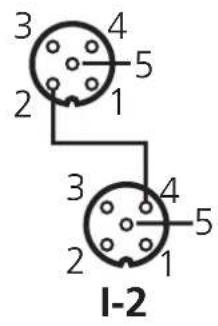
1-3/4
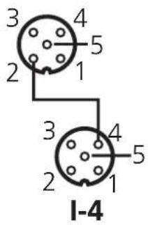
| M12 socket Pin | |
| sensor supply L+ | 1 |
| sensor supply L- 3 | |
| functional earth 5 |
| Data bit D0 | D1 D2 D3 | |||||
| input 1 2 B 4 | ||||||
| socket | I-1/2 | I-1/2 | I-2 | I-3/4 | I-3/4 | I-4 |
| pin | 4 | 2 | 4 | 4 | 2 | 4 |
Electrical connection
cULus-Class 2 source required.
Operation
Check the safe functioning of the unit. Display by LEDs:
• LED 1 yellow: input switched
• LED 2 green: AS-i supply voltage o.k.
- LED 3 red is lit: AS-i communication error, slave does not
participate in the "normal" exchange of data, e.g. slave address 0
• LED 3 red flashes: periphery fault, e.g. sensor supply overloaded or shorted
• LED 4: infrared receiver
Overload and short circuit of the input supply are signalled to the AS-i master (version 2.1) via the "peripheral fault" flag in the status register.
Maintenance
The operation of the module is maintenance-free.
Always exchange the upper part and lower part at the same time.
Installation
Disconnect the installation from power before mounting.
Select a plane mounting surface. The bottom of the module must lie flat on the mounting surface.
- Screw the lower part onto the mounting surface (mounting holes ① mounting screws not supplied).
- Insert the AS-i standard cable (yellow). Ensure correct positioning of the cable in the profiled slot.
- Put the upper part on the lower part and tighten the screws ② (screws supplied).
- Screw the upper part onto the mounting surface (mounting hole ③ mounting screw not supplied).
If the module is used at the end of the cable line, the ends of the two flat cables should be secured by means of shrink wraps (order no. E70113).
Cover the sockets not used with the enclosed protective caps to guarantee the protection rating IP67.
If required, you can ground the module via the earth springs (1*).
Technical data
You can download the data sheet from the Internet address www.ifm-electronic.com if required.
fixture infrared adapter
Brand : IFM
Model : AC2463
Category : Electronic module