VC13A - Multimeter VOLTCRAFT - Free user manual and instructions
Find the device manual for free VC13A VOLTCRAFT in PDF.

User questions about VC13A VOLTCRAFT
0 question about this device. Answer the ones you know or ask your own.
Ask a new question about this device
Download the instructions for your Multimeter in PDF format for free! Find your manual VC13A - VOLTCRAFT and take your electronic device back in hand. On this page are published all the documents necessary for the use of your device. VC13A by VOLTCRAFT.
USER MANUAL VC13A VOLTCRAFT
© Copyright 2016 by Conrad Electronic SE.

OPERATING INSTRUCTIONS
CE
VERSION 01/16
VC-13A ANALOG MULTIMETER
ITEM NO. 1386327
INTENDED USE
• M measuring and displaying electrical values in the range of measurement category CAT III up to max. 300 V against earth potential, pursuant to EN 61010-1
• Alternating and direct voltage measurements up to max. 300 V
• Measurement of direct current up to 250 mA
• Attenuation measurements from -20 dBm to +22 dBm
• Measurement of resistance up to 2 MOhm
• Battery test for 1.5 V and 9 V batteries
The multimeter may be operated only with a Mignon battery (AA, UM3, LR6 or equivalent).
The measuring instrument must not be used when it is open, i.e. with an open battery compartment or when the battery compartment cover is missing. Do not make measurements in potentially explosive areas (Ex) or damp rooms or under unfavourable ambient conditions. Adverse ambient conditions include: Damp or high humidity, dust and flammable gases, fumes or solvents, and thunderstorms or thunderstorm conditions like strong electrostatic fields, etc.
For safety reasons, when measuring only use measuring cables or accessories that are suitable for the specifications of the multimeter.
Measurements in circuits >33 V/AC and >70 V/DC may be carried out only by specialists and trained persons who are familiar with the pertinent regulations and the resulting dangers.
Any use other than that described above can lead to damage to the product and may involve additional risks such as short circuits, fire, electric shock etc. No part of the product may be modified or converted!
The safety instructions are to be observed without fail!
PACKAGE CONTENTS
- Multimeter
- Test leads
- Battery (Type AA)
- Operating instructions

Up-to-date Operating instructions:
1.Openwww.conrad.com/downloads in a browser or scan the displayed QR code.
2. Select document type and language and enter the item number into the search field. After submitting the query you can download displayed records.

DESCRIPTION OF SYMBOLS

An exclamation mark in a triangle indicates important information contained in these operating instructions that must be observed by all means.

The lightning symbol in a triangle warns of electric shock danger or the impairment of the electrical safety of the appliance.

The "arrow" symbol is used where special tips and notes on operation are provided.

This product has been CE tested and complies with the required European guidelines.

Class 2 insulation (double or reinforced insulation).
CAT III
Measurement Category III for measuring circuits of installations in buildings (e.g. electric sockets or sub-distributions). This category also includes all lower categories (e.g. CAT II for measuring on electrical devices and CAT I for measuring signal and control voltages). The measuring operation in CAT III is permitted only with probe tips with a maximum free contact length of 4 mm or with cover caps over the probe tips.

Earth potential
SAFETY INSTRUCTIONS

Please read all the instructions before using this device, they include important information on its correct operation.
es caused by failure to follow these operating instructions will void the warranty/guarantee! We do not assume any liability for any resulting damage!
not assume any liability for personal injuries and material damages caused by the improper use or non-compliance with the safety instructions! In such cases, the warranty will be null and void.

- This device has left our factory premises in a safe and perfect condition.
• We kindly request the user to observe the safety instructions and warnings contained in the enclosed operating instructions so this condition is maintained and to ensure safe operation.

authorised conversion and/or modification of the unit is not permitted for safety and approval reasons (CE).
- Consult a professional if you are unsure how to operate the equipment or how to connect it safely.
- Meters and their accessories are not toys and should be kept out of the reach of children!
• In commercial institutions, the accident prevention regulations of the Employer's Liability Insurance Association for Electrical Systems and Operating Facilities are to be observed. - In schools, training centres, hobby and self-help workshops, use of the measuring device must be supervised by trained personnel in a responsible manner.
- Before measuring voltages, always make sure that the measuring instrument is not set to a measuring range for currents.
- The voltage between any socket of the measuring instrument and earth may not exceed 300 V (DC/AC) in Measurement Category III.
- Be especially cautious when dealing with voltages exceeding >33 V (AC) or >70 V (DC)! Even at these voltages, there is a danger of fatal electric shock if you touch electric conductors.
- To eliminate the risks of electric shock, do not directly or indirectly touch the connections/measuring points during measurements. During measuring, do not grip beyond the tactile grip range markings on the test probes.
- Do not use the multimeter just before, during or just after an electrical storm (electrical shock! / high-power surges!). Make sure that your hands, shoes, clothing, the floor, the measuring device and/or measuring lines, circuits and circuit components are always dry.
- Do not use the tester in rooms or under adverse ambient conditions in which flammable gases, vapours or explosive dust may be or are present.
- Avoid operation near strong magnetic or electromagnetic fields, transmitter aerials or HF generators. These can distort the measurement.
- For safety reasons, use only measuring cables or accessories which are adjusted to the specifications of the multimeter when measuring. Only use double, or strengthened, insulated measuring accessories.
-
If you have reason to assume that safe operation is no longer possible, disconnect the device immediately and secure it against inadvertent operation. Safe operation can no longer be assumed if:
-
the device is visibly damaged,
- the device does not function any more and
- the device was stored under unfavourable conditions for a long period of time or
-
it has been subjected to considerable stress during transportation.
-
Do not switch the measuring instrument on immediately after it has been taken from a cold to a warm environment. The condensation that forms might destroy your device. Allow the device to reach room temperature before switching it on.
- Do not leave packaging material carelessly lying around, as it could become a dangerous plaything for children.
• Also pay attention to the safety instructions in each chapter of these instructions.
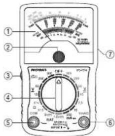
DESIGNATION OF INDIVIDUAL PARTS
text_image
① ② ③ ④ ⑤ ⑥ ⑦ RINJONE OFF VCC-2A 100Ω 100Ω 100Ω 100Ω 100Ω 100Ω 100Ω 100Ω 100Ω 100Ω 100Ω 100Ω 100Ω 100Ω 100Ω 100Ω 100Ω 100Ω 100Ω 100Ω 100μF 100μF 100μF 100μF 100μF 100μF 100μF 100μF 100μF 100μF 100μF 100μF 100μF 100μF 100μF 100μF 100μF 105Ω 105Ω 105Ω 105Ω 105Ω 105Ω 105Ω 105Ω 105Ω 105Ω 105Ω 105Ω 105Ω 105Ω 105Ω1 Analogue scale display
2 Calibration screw for scale pointer
3 0-Ohm calibration control for measuring resistance values
4 Rotary switch for setting the measuring functions and ranges
5 COM socket (reference measuring point, negative pole)
6 V/mA/Ω socket (positive pole)
7 Battery and safety compartment on the reverse side
PRODUCT DESCRIPTION
- The analogue multimeter (hereinafter referred to as multimeter) is equipped with a shock-attenuating pointer instrument.
• The multimeter can be used in any operating position.
• The mA-current range is protected against overload with a micro fuse. - The individual measuring functions and ranges are selected with a rotary switch.
- The multimeter can be used for up to CAT III max. 300 V for hobby or professional applications.
- On delivery, the measuring leads may be covered by protective sleeves. Before use, pull the sleeves off the safety plugs.
• After use, put them back for transport protection. - The scale pointer can be calibrated with the calibration screw. Perform this before each measurement to prevent inaccurate measurements.
EXPLANATION OF SYMBOLS AND SIGNS
| Overload, the resistance measuring range was exceeded | |
| Symbol for the built-in battery data | |
| Symbol for the built-in fuse | |
| OFF Switch position OFF | |
| COM Measurement reference potential, - for DC | |
| VmAΩ Measurement input for measurement potential, + for DC | |
| AC Symbol for alternating current | |
| DC Symbol for direct current | |
| V Volt (unit of electric voltage) | |
| mA Milliampere (unit of electric current, exp.-3) | |
| Ω | Ohm (unit of electrical resistance) |
| x10 | The resistance value read must be multiplied by 10 |
| x1k | The resistance value read must be multiplied by 1000 |
| dB | Decibels, attenuation in the 10 V AC voltage measurement circuit(0 dB = 1 mW/600 Ohm = 0.775 V) |
| BAT Battery test | |
| 9 V/1.5 V | Measurement range for batteries with 9 V or 1.5 V nominal voltage |
| REPLACE | The tested battery must be replaced |
| ? | The tested battery should be replaced as soon as possible |
| GOOD | The tested battery can be used |
START-UP
Before you can work with the measuring device in the resistance measurement range, you must first insert the enclosed battery. Insert the battery as described in the chapter "Cleaning and Maintenance".
Rotary switch (4)
- The individual measuring functions and ranges can be set using the rotary switch.
- If the rotary switch is set to "OFF", the measuring device is switched off.
• Always turn the meter off when it is not in use. - An automatic cut-off does not occur in the resistance range.
WEIGHING

Do not exceed the maximum permitted input values under any circumstances. Never touch circuits or parts of circuits when they may contain voltages greater than 33 V/ACrms or 70 V/DC! Risk of fatal injury! Before every measurement, check the meter and the connected measuring leads for damage such as cuts, cracks or pinches. Remove defective measuring leads immediately and replace them with new measuring cables. Defective measuring leads must no longer be used. ! Risk of fatal injury!
Before changing the measuring range, the test probes have to be removed from the measured object.
Always start each measurement with the largest measuring range. Then gradually change to a smaller one to achieve an exact measured result. The best precision occurs in the mid-scale range (scale range ca. 70^ to 110^ ).
The measuring results at the rotary switch correspond to the scale end value. For reading, always select the corresponding value (e.g. scale 10 for the measuring range 10).
a) Zero adjustment
Before each measurement, adjust the zero position with the calibration screw (2) (scale value 0 V). There must be no measuring signal on the measuring lines.
b) Measuring AC and DC voltages

Do not exceed the maximum permitted input values under any circumstances.
Proceed as follows to measure direct current (DC) voltages:
- Select the measuring function V with the rotary switch.
- Connect the black measuring line to the COM socket (5) and the red measuring line to the V socket (6).
- Pay attention to the correct polarity (red = + / black = -) and connect the two measuring tips in parallel to the object to be measured (battery, circuit, etc.).
- In the case of a pole reversal, the needle deflects in the negative direction. This could damage the meter mechanism. Stop the measurement at once and repeat the measurement with the correct polarity.
- Read off the measured value on the scale "V".
| DC V range | V scale for reading Multiplier | |
| 2.5 | 0 - 250 | 0.01 |
| 10 | 0 - 10 | 1 |
| 50 | 0 - 50 | 1 |
| 250 | 0 - 250 | 1 |
| 300 | 0 - 300 | 1 |
- After completing the measurement, remove the measuring tips from the measuring circuit and switch the multimeter off (rotary switch position: "OFF").
Proceed as follows to measure AC voltages:
- Select the measuring function V with the rotary switch ∼.
- Connect the black measuring line to the COM socket (5) and the red measuring line to the V socket (6).
- Now connect the two measuring probes in parallel to the object to be measured (generator, switch etc.).
- Read off the measured value on the scale "V".
- After completing the measurement, remove the measuring tips from the measuring circuit and switch the multimeter off (rotary switch position: "OFF").
c) Resistance measurement

Make sure that all the circuit parts, switches and components and other objects to be measured are disconnected from the voltage and discharged at all times.
Proceed as follows to measure resistances:
- Select the measuring function "Ω" with the rotary switch.
- Connect the black measuring line to the COM socket (5) and the red measuring line to the socket "Ω" (6).
- Touch the two measuring tips to each other and wait until the pointer has stabilised. A value of approx. 0 Ohm must be displayed. In case of a deviation, adjust the pointer with the 0 Ohm calibration control (3) to 0 Ohm. Always check this when changing the measuring range.
- Read off the measuring value on the scale "Ω".
- In the "x1k" measurement range, multiply the displayed value by a factor of 1000 to get the measured value e. g. 5 (display) × 1000 = 5× 1000 = 5k (measured value).
- In the “x10” measurement range, multiply the displayed value by a factor of 10 to get the measured value e. g. 50 Ω (display) x 10 = 50 x 10 = 500 Ω (measured value).
- After completing the measurement, remove the measuring tips from the measuring circuit and switch the multimeter off (rotary switch position: "OFF").
d) Direct current measurement

Never exceed the max. permitted input values in the respective measuring ranges. At measuring operations are permissible only in circuits up to max. 300 V.
Proceed as follows to measure direct currents up to 250 mA/DC voltages:
- Select the measuring function "mA" with the rotary switch.
- Connect the black measuring line to the COM socket (5) and the red measuring line to the socket "mA" (6).
- Disconnect the object to be measured from the mains.
- Pay attention to the correct polarity (red = + / black = -) and connect the two measuring tips in series with the measuring object (battery, circuit, etc.).
- In the case of a pole reversal, the needle deflects in the negative direction. This could damage the meter mechanism. Stop the measurement at once and repeat the measurement with the correct polarity.
- Read off the measuring value on the scale "mA".
- Disconnect the measured object from the mains and remove the measuring tips from the measuring circuit after the measurement is completed. Switch off the multimeter (rotary switch position "OFF").
e) Attenuation measurement in dBm
The multimeter enables absolute "dB" measuring in circuits with an impedance of 600 Ohm. Measurements are made in the "10 V\~" range. 0 dB = 1 mW (0.775 V).
Proceed as follows for the measurement:
- With the rotary switch, select the measuring range "10 V\~".
- Connect the black measuring line to the COM socket (5) and the red measuring line to the socket "V" (6).
- Now connect the two measuring probes in parallel to the object to be measured (generator, switch, etc.).
- Read off the measured value on the scale "dB". Read the voltage on the scale "AC10V".
- If signals with a direct voltage ratio are to be measured, a capacitor of >0.1nF must be connected in series to the measuring lines (decoupling).
- After completing the measurement, remove the measuring tips from the measuring circuit and switch the multimeter off (rotary switch position: "OFF").
f) Battery test
The multimeter tests 1.5 V or 9 V batteries with a low load. This prevents faulty measurements during open-circuit operation and gives significant clues to the battery condition.
| "REPLACE" indicates that the battery must be replaced. |
| "?" indicates that the battery can still be used only for low power consumer loads. |
| "GOOD" indicates that the battery is OK. |
To test the batteries, proceed as follows:
- With the rotary switch select the measuring function "BAT" and the measuring range 1.5 V or 9 V.
- Connect the black measuring line to the COM socket (5) and the red measuring line to the socket "V" (6).
- Pay attention to the correct polarity (red = + / black = -) and connect the two measuring tips to the battery.
- In the case of a pole reversal, the needle deflects in the negative direction. This could damage the meter mechanism. Stop the measurement at once and repeat the measurement with the correct polarity.
- Read off the measured value on the scale "BAT".
- After completing the measurement, remove the measuring tips from the measuring circuit and switch the multimeter off (rotary switch position: "OFF").
CLEANING AND MAINTENANCE
General information
To ensure the accuracy of the multimeter over an extended period of time, it should be calibrated once a year.
Information on changing the battery and fuse appears below.

Regularly check the technical safety of the device and the measuring cables, e.g. for damage to the housing or crimping, etc.
Never operate the meter when it is open. ! RISK OF FATAL INJURY!
Cleaning
Always observe the following safety instructions before cleaning the device:

Live components may be exposed if the covers are opened or parts are removed, unless this can be done manually without tools.
Before cleaning or repairing of the device, all the cables have to be detached and the device must be turned off.
Do not use any scouring cleansers, petrol, alcohol or the like to clean the product. These could corrode the surface of the measuring instrument. Furthermore, the fumes are explosive and hazardous to your health. Moreover, you should not use sharp-edged tools, screwdrivers, metal brushes or similar implements for cleaning.
To clean the device, the display or the measurement lines, use a clean, dry, lint-free anti-static cleaning cloth.
Inserting/changing the batteries
To use the measuring instrument in the resistance range, a Mignon (AA) type battery, included in the package, is required.
Insert a new battery:
- when using for the first time,
- when a 0-Ohm adjustment in the resistance measuring range can no longer be performed.
To insert/replace the battery, proceed as follows:
- Remove all the measuring leads from the device and turn the multimeter off.
- Loosen the screw on the rear of the battery compartment and carefully remove the cover (7) of the battery compartment by pulling it backwards.
- Now place a new battery into the battery compartment, observing the correct polarity. Look for the polarity signs in the battery tray.
- Now, close the cover carefully again.

Never operate the meter when it is open. ! RISK OF FATAL INJURY!
leave flat batteries in the device. Even batteries that are leak-proof can corrode and thus release chemicals that could be detrimental to your health or damage the device.
Leaking or damaged batteries might cause severe burns if they come into contact with the skin. Therefore, use suitable protective gloves.
Remove the battery if the device is not to be used for a long time, to prevent leaking.
Do not leave batteries lying around carelessly. They could be swallowed by children or pets. If swallowed, consult a doctor immediately.
Make sure that the batteries are not short-circuited. Do not throw batteries into a fire.
Batteries may not be recharged. There is risk of explosion.

You can order suitable alkaline batteries by stating the following order no.:
Order no. 652501 (please order 1x).
CHANGING THE FUSE

Always adhere carefully to the safety instructions when replacing the fuse!
are that only fuses of the type stated and of the rated current specified are used as a replacement. The use of incorrect or repaired fuses or a bypassing of the fuse holder is not permitted and can lead to a fire or to an arc explosion.
The measuring input is protected against overload. If you can no longer carry out measurements, you have to replace the internal high-performance fuse.
Proceed as follows to change the fuse:
- Remove all measuring leads and turn the multimeter off.
- Loosen the screw on the rear of the housing and carefully remove the cover (7) of the battery compartment by pulling it backwards.
- Replace the high-performance fuse with a new fuse of the same type and current strength.
• Ceramic F500mA H 500 V fast blowing 6.3 x 32 mm.
• Now, close the cover carefully again.
DISPOSAL


Electronic products are recyclable material and do not belong in the household waste. Dispose of an unserviceable product in accordance with the relevant statutory regulations.
the inserted battery and dispose of them separately from the product.
DISPOSAL OF USED BATTERIES/RECHARGEABLE BATTERIES!
As the end user, you are required by law (Battery Regulation) to return used batteries. Do not dispose of used batteries in the household waste!

Batteries/rechargeable batteries containing harmful substances are marked with the following symbols, they point out that they are not allowed to be disposed of in the household waste. The symbols of the relevant heavy metals are: Cd = cadmium, Hg = mercury, Pb = lead (the marking can be seen on the battery, e.g. underneath the refuse bin symbol shown on the left). You can return your used batteries/rechargeable batteries free of charge at the official collection points of your community, in our stores, or at places where batteries or rechargeable batteries are sold!
You thereby fulfil your statutory obligations and contribute to the protection of the environment!
TROUBLESHOOTING

In purchasing the multimeter, you have acquired a product which has been designed to the state of the art and is operationally reliable.
Nevertheless, problems or faults may occur. Therefore, we would like to describe here how you can solve any problems. Always observe the safety instructions!
| Error Possible cause | |
| No resistance measurement possible. | Is the battery dead?Check the state of the battery and, if necessary, the fuse. |
| No measurement possible. | Is the fuse defective?Check the fuse (fuse replacement). |
| No change in measured value. | Is the right measuring range and measuring mode selected (AC/DC)? |
| Incorrect measurement values are displayed. | Did you zero the display or carry out a 0-Ohm calibration for resistance measurement before beginning the measurement? |

Repairs other than described above are to be carried out exclusively by an authorised specialist.
If you have questions concerning the use of the meter, please contact our technical support team.
TECHNICAL DATA
| Max. measuring voltage 300 V | |
| Input resistance for V range | DC: approx.10 kΩ/VAc: approx. 4.5 kΩ/V |
| Power supply 1 Mignon battery 1.5 V (AA, UM3, LR6, etc.) | |
| Operating conditions 0 °C to +40 °C, <75% relative humidity, not condensing | |
| Storage temperature -10 °C to +50 °C, <80% relative humidity, not condensing | |
| Measurement category CAT III 300 V | |
| Pollution degree 2 | |
| Operating altitude max. 2000 m above sea level | |
| Protection class 2 | |
| Weight approx. 120 g | |
| Dimensions (L x W x H) 116 x 68 x 34 mm | |
| Length of the measuring cable approx. 650 mm | |
Measurement tolerances
Specification of the precision in ± (% of the scale value). The precision is valid for one year at a temperature of +23 °C ± 2 °C, and at a relative humidity of less than 60%, non-condensing.
Direct voltage range
| Range | Precision | Note |
| 2,5 V / 10 V / 50 V / 250 V / 300 V | ±4% | Internal resistance 10 kΩ / V |
Alternating voltage range (50/60 Hz)
| Range | Precision | Note |
| 10 V / 50 V / 250 V / 300 V | ±5% | Internal resistance 4.5 kΩ / V |
Direct current range
| Range | Precision | Note |
| 10 mA / 250 mA | ±4% | F500mA H 500V fast-blowing6.3 x 32 mm, ceramic |
Resistance range
| Range | Precision | Note |
| X10 / x1k | ±4% | Measurement voltage: -1.5 VMeasurement current (x10): approx. 15 mAMeasurement current (x1k): approx. 0.15 mA |
Battery test
| Range | Accuracy | Note |
| 1.5 V / 9 V | not specified |
Attenuation measurement dBm
| Range | Accuracy | Note |
| -20 dBm to +22 dBm | not specified | 10 V/AC measurement range0 dB = 1 mW / 600 Ω (0.775 V) |

Do not exceed the maximum permitted input values under any circumstances. Never touch circuits or parts of circuits when they may contain voltages greater than 33 V/ACrms or 70 V/DC! Risk of fatal injury!
GB Legal notice
This is a publication by Conrad Electronic SE, Klaus-Conrad-Str. 1, D-92240 Hirschau (www.conrad.com).
All rights including translation reserved. Reproduction by any method, e.g. photocopy, microfilming, or the capture in electronic data processing systems require the prior written approval by the editor. Reprinting, also in part, is prohibited. This publication represents the technical status at the time of printing.
© Copyright 2016 by Conrad Electronic SE.

MODE D'EMPLOI
CE
VERSION 01/16
MULTIMÈTRE ANALOGIQUE VC-13A
text_image
① ② ③ ④ ⑤ ⑥ VOUT VOUT VOUT VOUT VOUT VOUT VOUT VOUT VOUT VOUT VOUT VOUT VOUT VOUT VOUT VOUT VOUT VOUT VOUT VOUT VOUT© Copyright 2016 by Conrad Electronic SE.

GEBRUIKSAANWIJZING
CE
VERSIE 01/16
VC-13A ANALOGE MULTIMETER
BESTELNR. 1386327
BEOOGD GEBRUIK
PICTOGRAMBESCHRIJVING

© Copyright 2016 by Conrad Electronic SE. V1_0116_02/VTP