
460793 - Router table SILVERLINE - Free user manual and instructions
Find the device manual for free 460793 SILVERLINE in PDF.

| Product type | Router table with mitre gauge |
| Brand | Silverline |
| Model | 460793 |
| Dimensions (L x W x H) | 865 x 375 x 390 mm |
| Weight | 7 kg |
| Power supply | 220-250 V~ 50 Hz, 10 A |
| Recommended router power | 900 - 1800 W (4 - 8 A) |
| Max supported router weight | 3.5 kg |
| Max router base diameter | 155 mm |
| Max cutter diameter | 32 mm |
| Height under table to base | 270 mm |
| Table dimensions (W x D) | 450 x 335 mm |
| Dimensions with extensions (W x D) | 850 x 335 mm |
| Max workpiece dimensions (L x W x H) | 2000 x 100 x 55 mm |
| Main functions | Rebates, grooves, mouldings, planing, joinery, mortises |
| Safety | Hearing, eye, respiratory protection, cut-resistant gloves; emergency stop via control box |
| Maintenance and cleaning | Clean with soft cloth and mild detergent; light lubrication if necessary |
| Spare parts and repairability | Parts available from Silverline retailer or at toolsparesonline.com; repair by approved centre |
| Warranty | 3 years after registration on silverlinetools.com |
| Included accessories | Adjustable guide, mitre gauge, featherboards, table inserts, control box, guards |
Frequently Asked Questions - 460793 SILVERLINE
User questions about 460793 SILVERLINE
0 question about this device. Answer the ones you know or ask your own.
Ask a new question about this device
Download the instructions for your Router table in PDF format for free! Find your manual 460793 - SILVERLINE and take your electronic device back in hand. On this page are published all the documents necessary for the use of your device. 460793 by SILVERLINE.
USER MANUAL 460793 SILVERLINE
SILVERLINEC® Table With Protractor 025mm
Router Table With Power 850 x 335mm

natural_image
Black metal workbench with mechanical components and a 'YEAR GUARD REGN' badge (no visible text or symbols on the equipment itself)
text_image
YEAR GUARANTEE 3 REGISTER ONLINE*natural_image
3D rendering of a mechanical component with ribbed surface and central hole (no text or symbols)2
natural_image
Black plastic mechanical component with a central cylindrical feature and mounting holes (no text or symbols visible)3
natural_image
Black metal enclosure with mounting brackets and vertical supports (no text or symbols visible)4

natural_image
Black metal bracket with V-shaped cutouts and mounting holes (no text or symbols)5678

natural_image
Close-up of a black mechanical component with a circular button and attached cable (no visible text or symbols)
natural_image
Abstract geometric pattern of overlapping gray rings and a central square (no text or symbols)
natural_image
Circular black washer or wash plate with a central hole (no text or symbols visible)
natural_image
Circular black washer or wash plate with a central hole (no text or markings visible)15
natural_image
Metal V-shaped anchor bolt (no text or symbols visible)9 10

natural_image
Close-up of a black threaded screw with a flat head (no text or symbols visible)
natural_image
Close-up of a black hexagonal nut with a circular hole (no text or symbols visible)11
natural_image
Two black plastic mechanical components with circular holes, shown from different angles (no text or symbols visible)12
13
natural_image
Two metallic bolts with threaded ends, one plain and one with a black cap (no text or symbols visible)14

natural_image
3D rendered object resembling a stylized helmet or bracket (no text or symbols)16

natural_image
White circular washer or washer with a central hole, shown against a plain background (no text or markings visible)17 18 21

natural_image
Black four-pointed star-shaped object with a circular hole, resembling a knob or knob (no text or symbols visible)19 20
natural_image
Two black threaded rods hanging from a vertical line, no text or symbols visible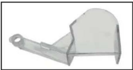
natural_image
3D rendered mechanical component with a curved handle and circular end (no text or symbols)22

text_image
b23
natural_image
Close-up of a metallic screw with threaded head and flange (no text or symbols visible)24 25
natural_image
Black metal T-shaped bracket with a hole, isolated on white background (no text or symbols)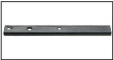
natural_image
Black metal rod with two circular holes, isolated on white background (no text or symbols)26

natural_image
Black semi-circular object with a white curved cutout, resembling a mechanical or architectural component (no text or symbols visible)27 28 30 31

natural_image
Close-up of a black mechanical component with a threaded shaft (no visible text or symbols)29
natural_image
Simple line drawing of a mechanical component with a handle and key (no text or symbols)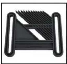
natural_image
Abstract geometric shape with black and white diagonal stripes, no text or symbols present
text_image
Exploded view diagram of a device with numbered parts for identification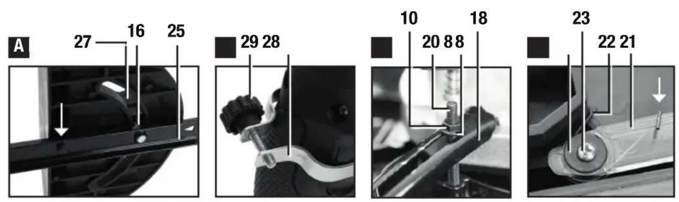
text_image
A 27 16 25 29 28 10 18 20 88 23 22 21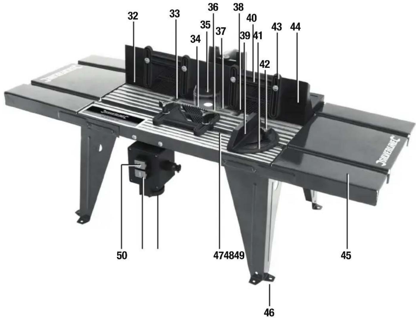
text_image
32 33 34 35 36 37 38 39 40 41 42 43 44 50 474849 46 45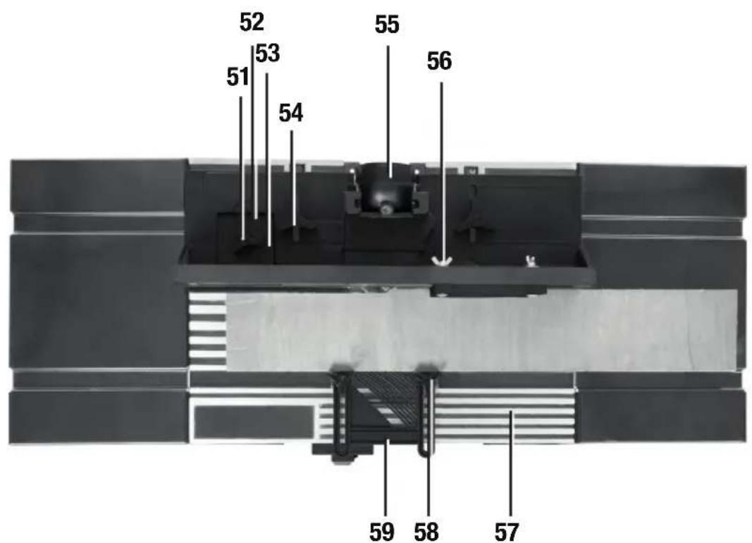
text_image
52 53 54 55 56 51 59 58 57SILVERLINEC® Table With Protractor
Router Table With Protection 850 x 335mm
English 6
Français ...... 14
Deutsch 22
Español 30
Italiano 38
Nederlands......46
Introduction
Thank you for purchasing this Silverline tool. This manual contains information necessary for safe and effective operation of this product. This product has unique features and, even if you are familiar with similar products, it is necessary to read this manual carefully to ensure you fully understand the instructions. Ensure all users of the tool read and fully understand this manual.
Description of Symbols
The rating plate on your tool may show symbols. These represent important information about the product or instructions on its use.

Wear hearing protection.
Wear eye protection.
Wear breathing protection.
Wear head protection.

Wear hand protection.

Read instruction manual.

Caution!

Conforms to relevant legislation and safety standards.

Environmental Protection
Waste electrical products should not be disposed of with household waste. Please recycle where facilities exist. Check with your local authority or retailer for recycling advice.
Technical Abbreviations Key
| V Volts | |
| ~, AC Alternating current | |
| A, mA Ampere, milli-Amp | |
| ∅ Diameter | |
| ° Degrees | |
| Hz Hertz | |
| W, kW Watt, kilowatt |
Specification
Voltage range: 220-250V\~50Hz
Max current: 10A
Max router weight: 3.5kg
Recommended router wattage: 900 - 1800W (4 - 8A)
Max workpiece dimensions (L x W x H): .....2000 x 100 x 55mm
Max router base diameter: 155mm (6")
Max router cutter diameter: 032mm
Under table height to base: 270mm
Table size (W x D): 450 x 335mm
Extensions (W x D): 200 x 335mm (x2)
Table size with extensions (W x D):....850 x 335mm
Bench Mounting size (W x D): 450 x 360mm
Protection class:
Dimensions (L x W x H): 865 x 375 x 390mm
Weight: 7kg
As part of our ongoing product development, specifications of Silverline products may alter without notice.
General Safety
WARNING: Read all safety warnings and all instructions. Failure to follow the warnings and instructions may result in electric shock, fire and/or serious injury.
WARNING: This appliance is not intended for use by persons (including children) with reduced, physical or mental capabilities or lack of experience or knowledge unless they have been given supervision or instruction concerning use of the appliance by a person responsible for their safety. Children must be supervised to ensure that they do not play with the appliance.
WARNING: When using electric tools basic safety precautions should always be followed to reduce the risk of fire, electric shock and personal injury including the following.
Read all these instructions before attempting to operate this product and save these instructions
Save all warnings and instructions for future reference.
The term "power tool" in the warnings refers to your mains-operated (corded) power tool or battery-operated (cordless) power tool.
1 - Keep work area clear - Cluttered areas and benches invite injuries
2 - Consider work area environment
- Do not expose tools to rain
- Do not use tools in damp or wet locations
- Keep work area well lit
- Do not use tools in the presence of flammable liquids or gases
3 - Guard against electric shock - Avoid body contact with earthed or grounded surfaces (e.g. pipes, radiators, ranges, refrigerators)
4 - Keep other persons away - Do not let persons, especially children, not involved in the work touch the tool or the extension cord and keep them away from the work area
5 - Store idle tools - When not in use, tools should be stored in a dry locked-up place, out of reach of children
6 - Do not force the tool - It will perform the job better and safer at the rate for which it was intended
7 - Use the right tool - Do not force small tools to do the job of a heavy duty tool
Do not use tools for purposes for which they are not intended; for example do not use circular saws to cut tree limbs or logs
8 - Dress appropriately
- Do not wear loose clothing or jewellery, which can be caught in moving parts
- Suitable safety footwear is recommended when working outdoors.
- Wear protective covering to contain long hair
9 - Use protective equipment
- Use safety glasses
- Use face or dust mask if working operations create dust
WARNING: Not using protective equipment or appropriate clothing can cause personal injury or increase the severity of an injury.
10 - Connect dust extraction equipment - If the tool is provided for the connection of dust extraction and collecting equipment, ensure these are connected and properly used
11 - Do not abuse the power cable - Never pull the power cable to disconnect it from the socket. Keep the power cable away from heat, oil and sharp edges. Damaged or entangled power cables increase the risk of electric shock
12 - Secure work - Where possible use clamps or a vice to hold the work. It is safer than using your hands
13 - Do not overreach - Keep proper footing and balance at all times
14 - Maintain tools with care
- Keeping cutting tools sharp and clean makes the tool easier to control and less likely to bind or lock in the workpiece
- Follow instructions for lubricating and changing accessories
- Inspect tool power cables periodically and have them repaired by an authorised service facility if damaged
- Inspect extension cables periodically and replace if damaged
- Keep handles dry, clean and free from oil and grease
WARNING: Many accidents are caused by poorly maintained power tools.
15 - Disconnect tools - Disconnect tools from the power supply when not in use, before servicing and when changing accessories such as blades, bits and cutters
WARNING: The use of accessories or attachments not recommended by the manufacturer may result in a risk of injury to persons.
16 - Remove adjusting keys and wrenches - Form the habit of checking to see that keys and adjusting wrenches are removed from the tool before switching it on
17 - Avoid unintentional starting - Ensure switch is in "off" position when connecting to a mains socket, inserting a battery pack, or when picking up or carrying the tool
WARNING: Unintended starting of a tool can cause major injuries.
18 - Use outdoor extension leads - When the tool is used outdoors, use only extension cords intended for outdoor use and so marked. Use of an extension cable suitable for outdoor use reduces the risk of electric shock
19 - Stay alert
- Watch what you are doing, use common sense and do not operate the tool when you are tired
- Do not use a power tool while you are under the influence of drugs, alcohol or medication
WARNING: A moment of inattention while operating power tools may result in serious personal injury.
20 - Check damaged parts
- Before further use of tool, it should be carefully checked to determine that it will operate properly and perform its intended function
- Check for alignment of moving parts, binding of moving parts, breakage of parts, mounting and any other conditions that may affect its operation
- A guard or other part that is damaged should be properly repaired or replaced by an authorised service centre unless otherwise indicated in this instruction manual
- Have defective switches replaced by an authorised service centre
WARNING: Do not use the tool if the on/off switch does not switch the tool on and off. The switch must be repaired before the tool is used.
21 - Have your tool repaired by a qualified person - This electric tool complies with the relevant safety rules. Repairs should only be carried out by qualified persons, otherwise this may result in considerable danger to the user
WARNING: When servicing use only identical replacement parts.
WARNING: If the power cable is damaged it must be replaced by the manufacturer or an authorised service centre.
22 - Power tool mains plugs must match the mains socket - Never modify the plug in any way. Do not use any adapter plugs with earthed (grounded) power tools. Unmodified plugs and matching sockets will reduce risk of electric shock
23 - If operating a power tool outside use a residual current device (RCD) - Use of an RCD reduces the risk of electric shock
NOTE: The term "residual current device (RCD)" may be replaced by the term "ground fault circuit interrupter (GFCI)" or "earth leakage circuit breaker (ELCB)".
WARNING: When used in Australia or New Zealand, it is recommended that this tool is ALWAYS supplied via Residual Current Device (RCD) with a rated residual current of 30mA or less.
WARNING: Before connecting a tool to a power source (mains switch power point receptacle, outlet, etc.) be sure that the voltage supply is the same as that specified on the nameplate of the tool. A power source with a voltage greater than that specified for the tool can result in serious injury to the user, and damage to the tool. If in doubt, do not plug in the tool. Using a power source with a voltage less than the nameplate rating is harmful to the motor.
Polarized Plugs (for North America only) To reduce the risk of electric shock, this equipment has a polarized plug (one blade is wider than the other). This plug will fit in a polarized outlet only one way. If the plug does not fit fully in the outlet, reverse the plug. If it still does not fit, contact a qualified electrician to install the proper outlet. Do not change the plug in any way.
Router Table Safety
⚠ WARNING: ALWAYS wear personal protective equipment;
• Hearing protection to reduce the risk of induced hearing loss
- Respiratory protection to reduce the risk of inhalation of harmful dust
- Cut-proof no-fray gloves to avoid possible injuries when handling router cutters and rough material due to sharp edges. Any gloves where fabric material can work loose with the possibility of fabric strands MUST not be used when operating the router table
- Safety glasses to avoid eye injury caused by flying particles
- Ensure all people in the vicinity of the work area use adequate protection. Keep bystanders a safe distance away.
WARNING: ALWAYS connect the dust extraction port on the router cutter guard to a suitable vacuum dust extraction system. Certain types of wood are toxic or may cause allergic reactions in people and animals, especially when exposed to very fine dust. ALWAYS wear appropriate respiratory protection in addition to vacuum dust extraction.
a) ONLY fit plunge routers that are listed as compatible in 'Specification' to the Router Table. Only fit router bits that are suitable for the installed plunge router, with shanks compatible with the collet installed.
b) NEVER reach to the underside of the router table when the router is connected to the power supply.
c) ALWAYS remove the router plunge spring and plastic base plate, before fitting the tool to the router table. This enables easy router bit change and height winder adjustment from above the table.
d) Keep your hands away from the cutting area. NEVER pass your hands directly over, or in front of, the revolving cutter. As one hand approaches the router bit, move it AWAY from the cutter, in an arc motion over the top of the router bit, to the out-feed side beyond the cutter. NEVER trail your fingers behind the workpiece and DO NOT use awkward hand positions. Use push sticks and blocks where necessary.
e) Do not attempt to perform tasks on workpieces shorter than 300mm (12") in length without using special fixtures or jigs. It is recommended to make work pieces oversize then cut to finished length.
f) ASSESS risks, benefits and alternatives BEFORE using push sticks, push blocks or other jigs and safety devices. In many applications the use of such contraptions is useful and safe, however, in others it can be dangerous. Push sticks can fly out of the operator's hand, when they come into contact with the revolving router bit, potentially causing serious injuries.
g) ALWAYS support large workpieces on the in-feed and out-feed sides of the router table, and where necessary, also to the sides. Use an additional stand wherever possible.
h) ALWAYS use guards, fences, horizontal and vertical featherboards etc., to guide the workpiece, counteract and avoid kickback, especially when routing small or narrow workpieces. Vertical featherboards attached to the fence also help prevent uncontrolled lift-up of the workpiece.
i) ALWAYS remove ALL loose objects from the table before operating. Vibrations may cause loose objects to move and come into contact with the cutter.
j) NEVER attempt to remove wood fragments or dust from the cutter with your hands, whilst the router bit is spinning. ALWAYS switch the router off, disconnect the machine from the power supply, and wait until the cutter has come to a standstill. ALWAYS use cut-proof gloves when touching the cutter, to avoid injury.
k) ALWAYS inspect the workpiece for nails, staples and other metal objects and foreign bodies. If the router cutter hits a concealed nail, the bit may be destroyed, high-velocity projectiles may be produced, kickback can occur, all of which can lead to serious injury.
I) WHEREVER possible, use blind cutting techniques, where the router bit does not protrude from underneath the workpiece. Keeping the cutter on the underside of the workpiece provides additional operator protection.
m) ONLY expose the smallest possible part of the cutter above the table surface. Keep any unused portion of the cutter below the table surface.
n) ALWAYS test any new setup by rotating the spindle by hand, with the machine disconnected from the power supply. Ensure proper cutter clearance to the throat place, fence and guard, before starting the machine.
o) ALWAYS use suitable throat plates, providing optimum clearance around the router bit.
p) ALWAYS use the router cutter guard, and adjust the guard to cover as much of the router bit as possible, as close to the workpiece as possible. This not only protects the user from accessing the revolving router cutter, it also provides effective dust extraction
q) LIMIT the depth of cut; NEVER remove too much material in one pass. Several passes with at smaller cutting depth are safer, and produce a better surface finish.
r) ENSURE to adjust the router cutter speed, according to router cutter diameter and material being cut. Use the speed selection dial on the plunge router.
s) ALWAYS feed AGAINST the rotation of the cutter. Both feed direction and rotation are indicated by arrows on the router table surface.
t) ALWAYS use the fence if using a cutter without bearing or pilot. ALWAYS support the workpiece firmly against the fence. NEVER remove the retractable guards on the fence. ALWAYS use a cutter with bearing or pilot for freehand work.
Additional safety information
- ONLY use router cutters in perfect working condition compatible with the specification of the router table and which are suitable for hand feeding operation (marked 'MAN' for manual operation according to EN 847-1)
- The bit must not enter the workpiece in the same direction as the feed direction, which is likely to cause the workpiece to climb (climb cutting) and may lead to loss of control during operation with the workpiece pulled away from the operator in a hazardous way
- Do not attempt to re-sharpen router cutters unless you specifically follow the manufacturer's instructions and have the equipment to do so. The majority of router cutters have blades that cannot be re-sharpened and must be replaced immediately if dull
- Do not create fence traps caused by improper fence location. Fence traps happen when the fence is positioned so far back that the front side of the workpiece would be behind the router cutter. These are dangerous due to the risk of climb cutting and the difficulty of keeping the workpiece against the fence
- Ensure the correct table insert (table ring) is fitted that is the correct size for the size of the router cutter fitted
- Never use a router table until fully assembled and always re-check fasteners after re-assembly after storage
- Make certain the router is not plugged into the power outlet when installing into the table or when making adjustments or changing accessories
- DO NOT plug the router into a standard mains wall socket. It must be plugged into the router table switch box so can be switched off in emergency situations
-
The router table must be installed on a solid level surface and secured so the table will not tip. Use of auxiliary in-feed and out-feed supports is necessary for long or wide workpieces. Long workpieces without adequate support could cause the table to tip towards the operator causing injury
-
Routers create a lot of vibration and can work loose from their mountings. Check the mountings frequently and re-tighten if necessary
- Never start the tool with the router cutter already engaged in the workpiece. This can lead to a lack of control and possible injury
- The router table is designed to cut flat, straight and squared material only. Do not cut material that is warped, uneven, weak or made from inconsistent material. If necessary make sure material is correctly prepared before use. Incorrect material can lead to a lack of control and possible injury
WARNING: Unmaintained tools can cause uncontrolled situations. ONLY use router cutters that are correctly sharpened, maintained and adjusted in accordance with the manufacturer's instructions.
Note: Seek professional training and assistance before attempting work that require procedures you are not familiar with. STOP using the router table, if, at any point during operation, you encounter difficulties or are uncertain how to proceed safely.
Product Familiarisation
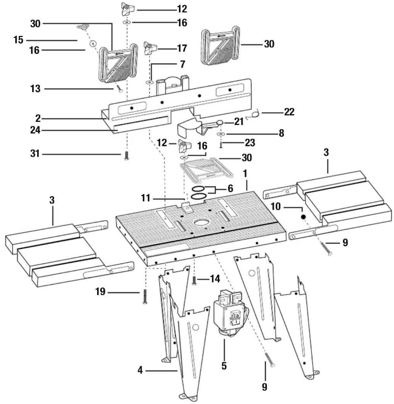
Parts List
| 1 Table (x 1) |
| 2 Fence & Guard Assembly (x 1) |
| 3 Table Extension (x 2) |
| 4 Leg (x 4) |
| 5 Switchbox (x 1) |
| 6 Table Inserts (5 sizes) |
| 7 Large Washer (x 3) |
| 8 Small Washer (x 5) |
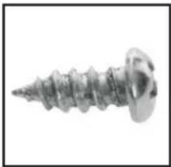
| 9 Phillips Head Bolt (x 20) |
| 10 Nut (x 24) |
| 11 Featherboard Pad (x 2) |
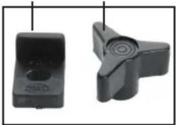
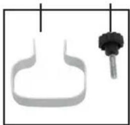
| 12 Knob (x 3) |
| 13 Featherboard Coach Bolt (x 4) |
| 14 Fence Bolt (x 2) |
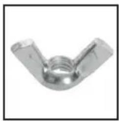
| 15 Featherboard Wing Nut (x 4) |
| 16 Large Washer (x 7) |
| 17 Fence Knobs (x 2) |
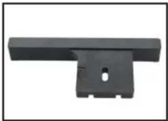
| 18 Router Securing Bar (x 4) |
| 19 Bolt (x 2) |
| 20 Router Securing Bolts (x 4) |
| 21 Guard (x 1) |
| 22 Guard Spring (x 1) |
| 23 Guard Screw (x 1) |
| 24 Adjustable Fence (x 1) |
| 25 Protractor Guide Bar (x 1) |
| 26 Protractor Body (x 1) |
| 27 Protractor Knob (x 1) |
| 28 Router Trigger Clamp (x 1) |
| 29 Router Trigger Clamp Knob (x 1) |
| 30 Featherboard (x 3) |
| 31 Short Bolt (x 1) |
Assembled
| 32 | Adjustable Fence |
| 33 | Table Scale |
| 34 | Direction Indicator |
| 35 | Guard |
| 36 | Table Insert Mounting |
| 37 | Guard Moving Point |
| 38 | Feathers |
| 39 | Protractor |
| 40 | Featherboard Direction Indicator |
| 41 | Protractor Angle Scale |
| 42 | Protractor Knob |
| 43 | Vertical Featherboard |
| 44 | Main Fence |
| 45 | Protractor Channel |
| 46 | Bench Mounting Holes |
| 47 | Horizontal Featherboard Mounting |
| 48 | Mains Socket |
| 49 | On Button |
| 50 | Off Button |
| 51 | Adjustable Fence Knob |
| 52 | Adjustable Fence Scale |
| 53 | Adjustable Fence Indicator |
| 54 | Main Fence Knob |
| 55 | Dust Extraction Port |
| 56 | Vertical Featherboard Wingnut |
| 57 | Main Table |
| 58 | Horizontal Featherboard Knob |
| 59 | Horizontal Featherboard |
Intended Use
Router table for temporary or permanent bench mounting or alternatively fitting to a dedicated tool stand. Capable of edge rebating, trenching, cross trenching, planing, edge moulding (fence and freehand), end grain work, jointing, using a template guide, and morticing. For use with the routers from 900W to 1800W power with a circular or semi-circular base with a diameter 155mm or less.
Unpacking Your Tool
- Carefully unpack and inspect your tool. Fully familiarise yourself with all its features and functions
- Ensure that all parts of the tool are present and in good condition. If any parts are missing or damaged, have such parts replaced before attempting to use this tool
Before Use
WARNING: Ensure the tool is disconnected from the power supply before attaching or changing any accessories, or making any adjustments.
Assembling the router table
See the exploded diagram at the beginning of the manual for a general quick view of how the table fits together then follow the instructions below.
Table
- Place the Table (1) upside down on a flat surface that will not scratch or damage the parts or allow the parts to move
- Line up the Table Extensions (3) ready for attachment on both ends of the Table
- Fit one Leg (4) into the recess of the Table and insert a Phillips Head Bolt (9) through the Table Extension, through the Table and finally through a mounting hole of the Leg. Fit a Nut (10) onto the thread of the bolt and tighten loosely
Note: The Legs fit inside the underneath of the Table whereas the Table Extensions are mounted on the external sides of the Table.
- Repeat until the Leg is secured for that corner and then repeat for all Legs until the main Table, Table Extensions and Legs are all fitted. Tighten so the Legs and Table Extensions can still be moved by hand but hold the position they are left in. This allows for adjustment before final tightening
- Check the flat surface you are using is level with a spirit level for both axes. Turn the router table over and check all the bench-mounting feet are level and flat on the surface. Use a spirit level to check the Table and Table Extensions are level on both axes and adjust the position of the Legs and Table Extensions if necessary
-
Once level carefully tighten the Nuts to lock that position. Do not over-tighten. Make sure the router table remains level after tightening and does not rock
-
Attach the Switchbox (5) to the underside front of the Table using two Phillips Head Bolts (9) and two Nuts (10)
-
Fit the Horizontal Featherboard using one of the Featherboards (30), both Featherboard Pads (11), two Knobs (12) and both Fence Bolts (14). The pads should be placed into the channel of the Table with the raised edges of the pads placed to the left and right side of the Featherboard
IMPORTANT: Note the direction of the Featherboard feathers in the main image of the Router Table. It is important that both vertical and the horizontal Featherboards are facing the correct way to work with the feed direction as shown.
Mounting the router
IMPORTANT: If the router is earthed the Switchbox (5) and any mains extensions used must be earthed and connected to an earthed power point.
- Please refer to the specification and check the router you intend to use is compatible
- Have your original router manual to hand and read before mounting. Make sure mounting won't restrict changing bits. Check that you still have easy access to the spindle lock button, adjusting router height and the collet securing nut
- Ensure the base of the router is completely clean so it will be level with the mounting plate when fitted
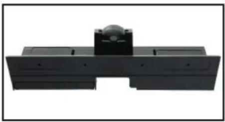
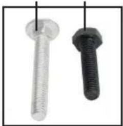
- If the Router doesn't feature a trigger lock-on feature, use the Router Trigger Clamp (28) and Router Trigger Clamp Knob (29) to lock the trigger in the on mode (Image B) or lock the trigger on
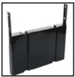
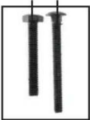
- Insert the four Router Securing Bolts (20) through the Table (1) surface and on the underside fit a Router Securing Bar (18), Small Washer (8) and Nut (10) to each bolt. Only loosely fit together at this stage
- Turn the Table (1) upside down making sure each Router Securing Bolt is still locked in the recess of the Table to prevent turning and move the Router Securing Bars so they face away from the centre to allow fitting of the router
- Carefully lower the router into the central recess of the Table ensuring the router is centred so the bit is dead centre in the Table opening. This is critical so take time to get this right
- Use the Router Securing Bars to secure the base of the router to the underside of the Table (Image C) then tighten all Nuts. Router bases vary in design and you will need to adapt to the shape of the base. Check the base is securely gripped and the Router Securing Bar are not blocking any feature of the base, for example the router's own dust extraction fittings
Note: Once you start using the router table, remember to recheck these fittings after a short amount of use to make sure they have not loosened. Then make it a regular check in the future. If the router drops from its mountings it may be damaged or destroyed.
- Recheck the router is correctly centralised and that you are happy with its position for access to all its features
- Finally connect the power cable of the router to the Mains Socket (48) but make sure at this point the Switchbox is not connected to a mains supply
Fence & Guard
- Attach the Adjustable Fence (24) to the Fence & Guard Assembly (2) using a Knob (12), Large Washer (16) and Short Bolt (31)
- Attach the Guard (21) to the Fence & Guard Assembly using Guard Screw (23), Small Washer (8) and the Guard Spring (22). See image D for how the spring attaches. Take time to make sure the Guard moves smoothly as it is an important safety feature
- Attach 2 of the Featherboards (30) to the Fence & Guard Assembly to be used as vertical Featherboards using Featherboard Coach Bolts (13), Large Washers (16) and Featherboard Wing Nuts (15)
- Attach the assembled Fence & Guard Assembly to the Table using two Bolts (19), Large Washers (7) and Fence Knobs (17). Use the two Table Scales (33) to mount in a level position
Bench mounting
It is important the Router Table is securely mounted especially when working with long workpieces. The Router Table can be secured to a workbench or a dedicated work stand. Alternatively the table can be attached to a piece of wood which can then be clamped to another work surface when needed which allows for easy removal. It is not designed to be used without being attached to another surface.
- Use screws or bolts (not supplied) through the Bench Mounting Holes (46) to secure the Table (1)
Assembling the Protractor
- Assemble the Protractor using the Protractor Body (26), Protractor Guide Bar (25), Protractor Knob (27) and a Large Washer (16). The guide bar fits over the pin (arrowed in Image A) and the Protractor Knob secures the assembly
Connecting dust extraction
IMPORTANT: Dust from certain materials and surface coatings can be toxic. Use a dust extraction system or vacuum whenever possible.
- If possible create a dual extraction system using both the Dust Extraction Port (55) of the Table for extraction above the Table and use the dust extraction port of your router which will operate below the Table. This is the ideal solution however using just the Dust Extraction Port (55) of the router table will be sufficient. When using just the table's own dust extraction port the correct size of Table Insert becomes more important which will keep more dust and chippings on top for easy extraction
- In the absence of dust extraction work for short periods only and clean the table frequently. This is not recommended
Configuring the router
For setting up your router refer to your router manual. Once setup fit the correct size Table Insert (6) to match the size of router bit fitted. Place over the router bit and turn to lock in position. Ensure there is a small gap around the edge of the router bit blade so the blade and Table Insert can never touch either in use or when changing bits
Operation
WARNING: ALWAYS wear eye protection, adequate respiratory and hearing protection, as well as suitable non-fabric gloves, when working with this tool.
Switchbox operation
IMPORTANT: The switchbox requires a live mains connection to switch ON. It will reset to OFF as soon as power is disconnected and require resetting to ON when power is restored to continue operation.
Switching on and off
The Switchbox (5) controls power to the router bypassing the normal router on/off button which is set permanently on.
- Connect the Switchbox lead to a wall socket and switch on
- Switch the router on by pressing the On Button (49) 'I'
- Switch off the router by pressing the Off Button (50) 'O'
User position and feed direction
- The main user position is defined by the location of the Switchbox (5)
- ALWAYS remain positioned in close proximity to the switch, so the machine can be instantly switched off in the case of emergency
- Feed workpieces from this position in the direction indicated by the arrows on the table which is feed from the right side of the table (input) to the left side (output)
Using the router table
As with most woodworking accurate measurement and pre-cut setup is critical to getting the right results. This manual is only a basic guide to operation. For best results seek further training or reading material. It is recommended to use scrap material while getting used to operating this table.
- Wear eye protection
- Check router fittings and collet nut is tight before use
- Feed workpiece against rotation of cutter. Feed direction is shown by on the fence and featherboards
- With your hands not awkwardly positioned hold the workpiece securely
- Keep fingers away from the revolving cutter. Use the featherboards when possible
-
Both the Vertical Featherboards (43) and Horizontal Featherboard (59) are used to apply light pressure to the workpiece to hold it more securely as it is cut. To adjust the height of the Vertical Featherboards loosen the Vertical Featherboard Wingnuts (56) and reposition the height then retighten. For the Horizontal Featherboard loosen the Horizontal Featherboard Knob (58) adjust and re-tighten
-
Use the Protractor (39) fitted to the Protractor Channel (45) to present angled workpieces to the cutting point. To adjust the Protractor angle loosen the Protractor Knob (42) and use the Protractor Angle Scale (41). Remove the Horizontal Featherboard if necessary
- For some cuts the Adjustable Fence (32) is used. This allows workpieces which have been cut into a shorter width to be supported after the cut. This is an often used function especially for making joints. To alter the Adjustable Fence position, loosen the Adjustable Fence Knob (51) and adjust the position using the Adjustable Fence Scale (52) and Adjustable Fence Indicator (53). Typical use would be to make a small first cut with scrap material and then align the Adjustable Fence with the scrap wood before then making the required cut on another workpiece
- To alter the Main Fence (44) position loosen the two Main Fence Knobs (54) and adjust its position using the Table Scales (33) then retighten the Main Fence Knobs
- Other adjustments are made using your router including cutter height. Refer to your router manual
Accessories
- A wide range of accessories for this tool, including a Machine Tool Stand (126657), Roller Stands (675120), Push Stick (675346), PPE equipment and router bits, is available from your Silverline stockist. Replacement parts are available from your Silverline stockist or www.toolsparesonline.com
Maintenance
⚠ WARNING: ALWAYS disconnect from the power supply before carrying out any inspection, maintenance or cleaning.
General inspection
• Regularly check that all the fixing screws are tight
- Inspect the supply cord of the tool, prior to each use, for damage or wear. Repairs should be carried out by an authorised Silverline service centre. This advice also applies to extension cords used with this tool
Cleaning
- Keep your tool clean at all times.
- Clean the tool casing with a soft damp cloth using a mild detergent. Do not use alcohol, petrol or strong cleaning agents
- Never use caustic agents to clean plastic parts
Other maintenance
- If cleaning does not return correct operation use dry or thin lubricants to keep the tool in good operation. Ensure the guard is always working correctly, lubricate if necessary
- Where paint has been worn off, repaint those small areas to prevent corrosion
Storage
- Store this tool carefully in a secure, dry place out of the reach of children
Disposal
Always adhere to national regulations when disposing of power tools that are no longer functional and are not viable for repair.
- Do not dispose of power tools, or other waste electrical and electronic equipment (WEEE), with household waste
- Contact your local waste disposal authority for information on the correct way to dispose of power tools
Troubleshooting
| Problem Possible cause Solution | ||
| Router will not operate | No power Check the Switchbox (5) is connected to a live mains connection | |
| Router mains plug not connected to Switchbox socket Connect router mains plug to Switchbox | ||
| Router on/off switch not on or Router Trigger Clamp not fitted | Ensure router on/off switch is locked or clamped in on position | |
| Router incorrectly setup Follow information in router manual | ||
| Router faulty Get router repaired or replace | ||
| Switchbox will not stay on Wattage of router too high. See Specification | ||
| Router runs or cuts slowly | Router incorrectly set up See router manual | |
| Wattage of router is too low for use with router table See Specification | ||
| Excessive vibration | Router incorrectly mounted Secure router to table correctly | |
| Router table not bench mounted or not secured to surface with clamps | Secure router table correctly. See ‘Bench Mounting’ | |
| Router too powerful for table See Specification and fit a compatible router to table | ||
Silverline Tools Guarantee
This Silverline product comes with a 3 year guarantee
Register this product at www.silverlinetools.com within 30 days of purchase in order to qualify for the 3 year guarantee. Guarantee period begins according to the date of purchase on your sales receipt.
Registering your purchase
Registration is made at silverlinetools.com by selecting the Guarantee Registration button. You will need to enter:-
- Your personal details
• Details of the product and purchase information
Once this information is entered your guarantee certificate will be created in PDF format for you to print out and keep with your purchase.
Terms & Conditions
Guarantee period becomes effective from the date of retail purchase as detailed on your sales receipt.
PLEASE KEEP YOUR SALES RECEIPT
If this product develops a fault within 30 days of purchase, return it to the stockist where it was purchased, with your receipt, stating details of the fault. You will receive a replacement or refund.
If this product develops a fault after the 30 day period, return it to:
Silverline Tools Service Centre PO Box 2988
Yeovil BA21 1WU, UK
The guarantee claim must be submitted during the guarantee period.
You must provide the original sales receipt indicating the purchase date, your name, address and place of purchase before any work can be carried out.
You must provide precise details of the fault requiring correction.
Claims made within the guarantee period will be verified by Silverline Tools to establish if the deficiencies are related to material or manufacturing of the product. Carriage will not be refunded. Items for return must be in a suitably clean and safe state for repair, and should be packaged carefully to prevent damage or injury during transportation. We may reject unsuitable or unsafe deliveries.
All work will be carried out by Silverline Tools or its authorized repair agents.
The repair or replacement of the product will not extend the period of guarantee
Defects recognised by us as being covered by the guarantee shall be corrected by means of repair of the tool, free of charge (excluding carriage charges) or by replacement with a tool in perfect working order.
Retained tools, or parts, for which a replacement has been issued, will become the property of Silverline Tools.
The repair or replacement of your product under guarantee provides benefits which are additional to and do not affect your statutory rights as a consumer.
What is covered:
The repair of the product, if it can be verified to the satisfaction of Silverline Tools that the deficiencies were due to faulty materials or workmanship within the guarantee period.
If any part is no longer available or out of manufacture, Silverline Tools will replace it with a functional replacement part.
Use of this product in the EU.
What is not covered:
Silverline Tools does not guarantee repairs required as a result of:
Normal wear and tear caused by use in accordance with the operating instructions eg blades, brushes, belts, bulbs, batteries etc.
The replacement of any provided accessories drill bits, blades, sanding sheets, cutting discs and other related items.
Accidental damage, faults caused by negligent use or care, misuse, neglect, careless operation or handling of the product.
Use of the product for anything other than normal domestic purposes.
Change or modification of the product in any way.
Use of parts and accessories which are not genuine Silverline Tools components. Faulty installation (except installed by Silverline Tools).
Repairs or alterations carried out by parties other than Silverline Tools or its authorized repair agents.
Claims other than the right to correction of faults on the tool named in these guarantee conditions are not covered by the guarantee.
Battery Guarantee
Silverline batteries are guaranteed for 30 days. If a defect occurs on a registered battery during the term of the Battery Guarantee, due to material or manufacturing fault, then Silverline will replace it free of charge. This guarantee does not apply to commercial use nor does it extend to normal wear and tear or damage as a result of accident, abuse or misuse.
Introduction
Fräser: max. ∅ 32 mm
Silverline Tools Service Centre
PO Box 2988
Yeovil
Silverline Tools Service Centre
PO Box 2988
Yeovil
BA21 1WU, GB
Silverline Tools Service Centre
PO Box 2988
Yeovil
BA21 1WU, GB
natural_image
Black metal workbench with mechanical components and a mounted device (no visible text or symbols)
3 Year Guarantee
*Register online within 30 days. Terms & Conditions apply
