
T2 Pro XT AddOn - Bike rack THULE - Free user manual and instructions
Find the device manual for free T2 Pro XT AddOn THULE in PDF.
| Type | Towbar bike rack, add-on module |
| Brand | Thule |
| Model | T2 Pro XT AddOn |
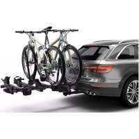
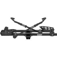
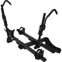
| Use | Add-on to an existing Thule T2 Pro XT bike rack, to carry up to 2 additional bikes |
| Attachment | On ball-type towbar |
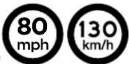
| Maximum permitted speed | 130 km/h (80 mph) |
| Speed over speed bumps | 10 km/h (6 mph) maximum |
| Rear capacity reduction | 60% of total load on motor vehicles with overhang > 230 cm |
| Bike compatibility | Standard frames (max diameter according to assembly instructions), tandems and recumbent bikes not compatible |
| Maximum weight per bike | Consult the assembly instructions (respect the vehicle's limit) |
| Materials | Steel frame, alloy arms, rubber/polymer straps |
| Maintenance | Clean with hot water or car shampoo, remove before automatic car wash, check strap wear |
| Safety | Check tightness after 50 km and regularly, do not use bungee cords, remove keys during transport |
| Spare parts | Only genuine Thule parts, order with serial number |
| Warranty | See Thule conditions - off-road use not covered |
| Regulations | May require rear lights and license plate according to local legislation |
Frequently Asked Questions - T2 Pro XT AddOn THULE
User questions about T2 Pro XT AddOn THULE
0 question about this device. Answer the ones you know or ask your own.
Ask a new question about this device
Download the instructions for your Bike rack in PDF format for free! Find your manual T2 Pro XT AddOn - THULE and take your electronic device back in hand. On this page are published all the documents necessary for the use of your device. T2 Pro XT AddOn by THULE.
USER MANUAL T2 Pro XT AddOn THULE
natural_image
Black and white illustration of a fleet with triceps and bow tie, no text or symbols present
EN HITCH MOUNTED BIKE RACKS
FR PORTE-VÉLOS SUR ATTELAGE
ES PORTABICICLETAS PARA ENGANCHE
PT SUPORTE PARA BICICLETA DE ENGATE AMERICANO


natural_image
Line drawing of a boat hull with rectangular compartments (no text or symbols)x2
x2
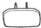
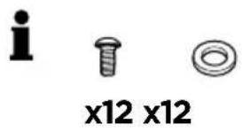
x2 x2

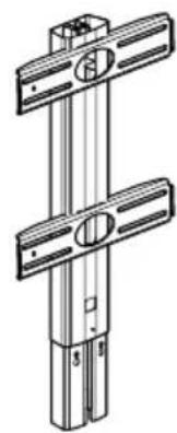
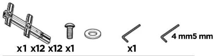
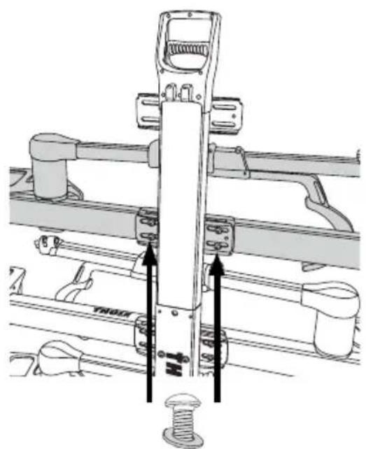
natural_image
Technical line drawing of a mechanical assembly with two vertical rods and a central circular feature (no text or symbols)x1

x12 x1

x12
x1

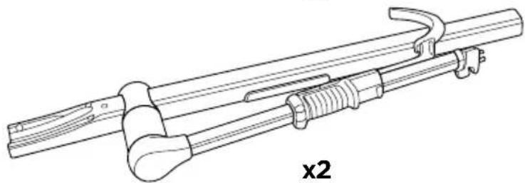
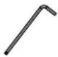
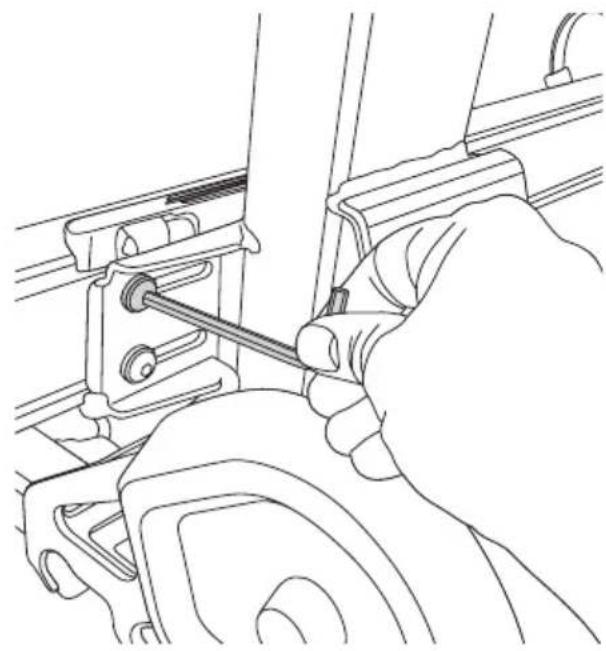
natural_image
Technical line drawing of a mechanical tool or bracket assembly (no text or symbols)
x2
x2
x1
i
natural_image
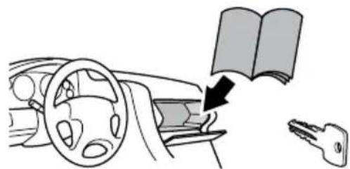
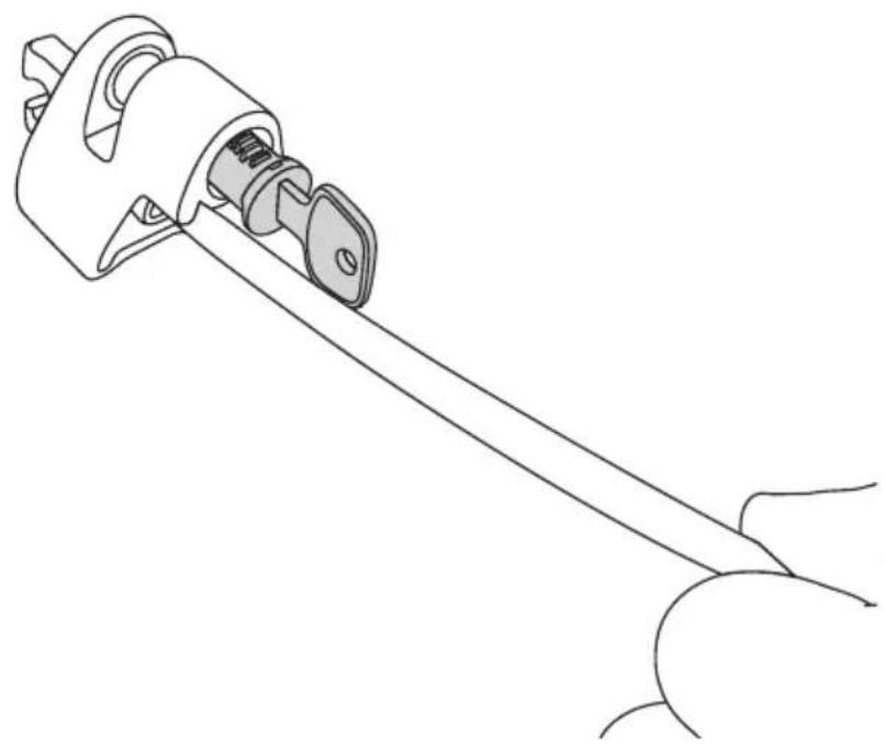
Diagram showing a car interior with steering wheel, dashboard, and key inserted into the window (no text or symbols)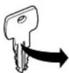
Your Key-Number

IMPORTANT - READ THE INSTRUCTIONS CAREFULLY BEFORE USE AND KEEP FOR FUTURE REFERENCE.
Symbols

WARNING indicates a hazardous situation which, if not avoided, could result in death or serious injury.

CAUTION indicates a hazardous situation which, if not avoided, could result in minor or moderate injury.

Note indicates additional information that is useful for trouble-free and optimal use of the product.
Motorized RV* travel at 60% load capacity (i.e., 40% total load reduction) when mounted on van conversions or motorized RV vehicles with an overhang exceeding 230 cm (7.5 ft), measured from the center of the rear wheel to the most distant rear point of the vehicle.
WARNING! This carrier is not compatible with travel trailers/caravans, 5th wheels or any bumper mounted hitch receiver.
* Refer to definition 49 CFR 571.3 (c) "Motor home", National Highway Traffic Safety Administration, Department of Transportation.
FR
natural_image
Black-and-white illustration of military equipment including tanks and missiles (no text or symbols)
Max 40 lbs. (23 kg)


Max 160 lbs. (72.5 kg)
natural_image
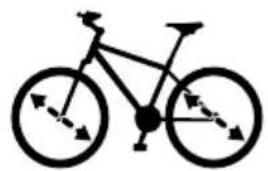
Simple line drawing of a bicycle with no text or symbols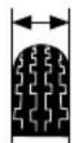
Max 5"
natural_image
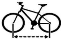
Diagram of a bicycle with two wheels and a dashed measurement line (no text or labels)Max 50.5"Min 20" Max 29"

natural_image
Simple line drawing of a bicycle (no text or symbols)


natural_image
Silhouette of a bicycle with front wheel and side panels (no text or symbols)


natural_image
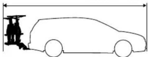
Side profile illustration of a car with two people standing beside it, no text or symbols present
200 miles / 333 km
natural_image
Illustration of a person using a pulley system to lift a weight (no text or symbols present)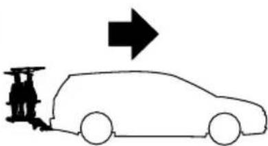
natural_image
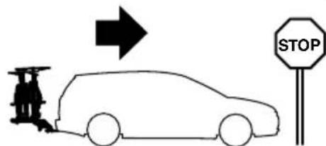
Silhouette of a person standing beside a car with an arrow pointing upward (no text or symbols)1 i
natural_image
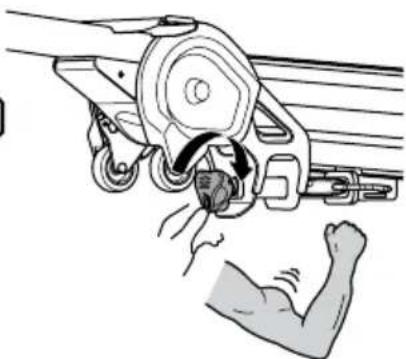
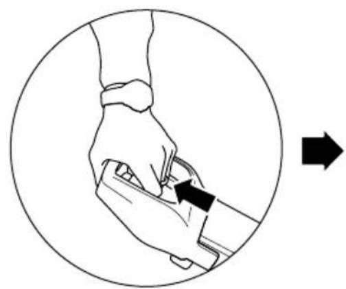
Illustration of a hand holding a wrist with a finger, enclosed in a circle and with an arrow indicating motion (no text or symbols)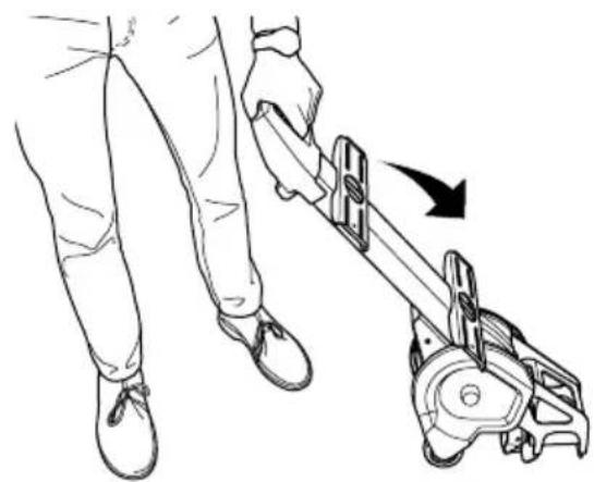
natural_image
Line drawing of a person using a mechanical tool to lift a cart, showing motion direction (no text or symbols)A
C
natural_image
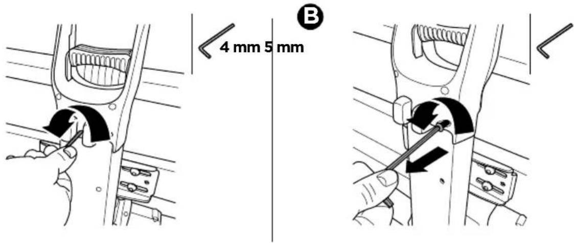
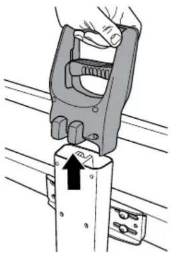
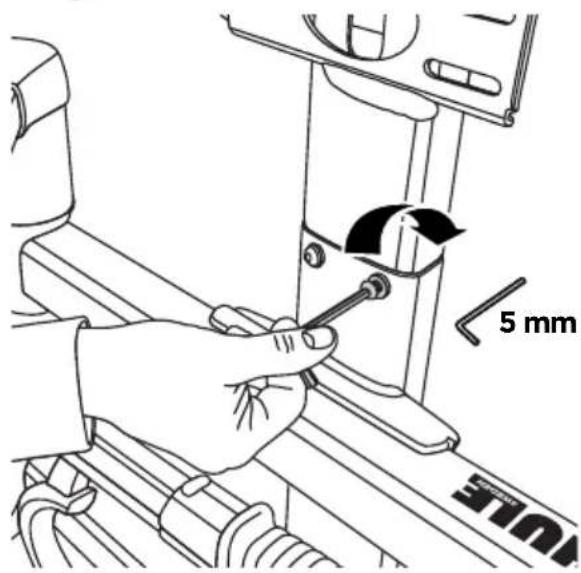
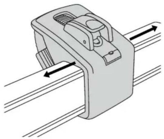
Illustration of a hand using a clamp to lift a vertical pole, with an arrow indicating force direction (no text or symbols present)2
3
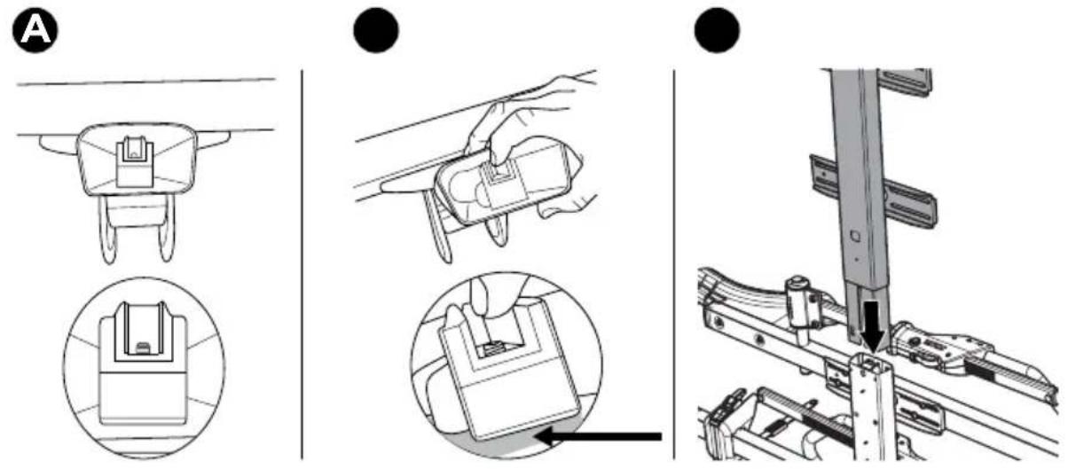
A

4 mm
B

5 mm
natural_image
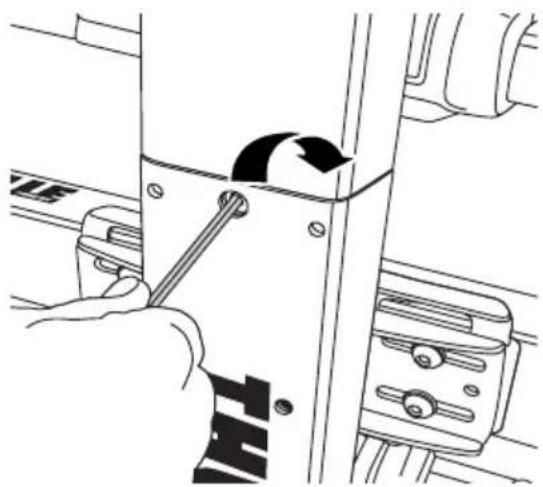
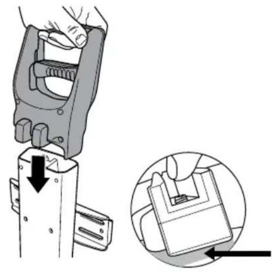
Illustration of a hand using a tool to adjust or install a mechanical component, with no visible text or symbols.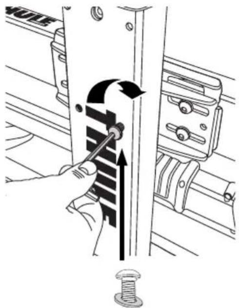
natural_image
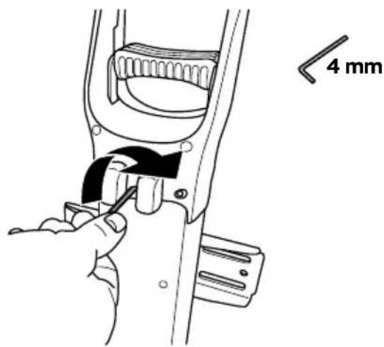
Illustration of a hand using a tool to adjust a mechanical component, showing no text or symbols.C
4
A
natural_image
Illustration of a hand using a clamp tool to adjust a component, with an inset showing the close-up of the component (no text or symbols present)B
C
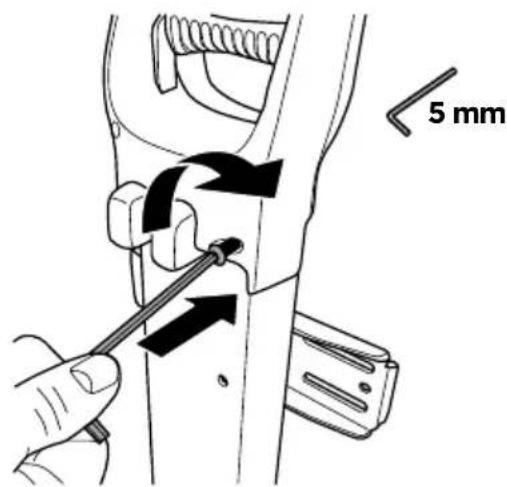
5
A
natural_image
Technical diagram of a mechanical assembly with springs and bolts, no visible text or symbolsB
natural_image
Line drawing of a hand using a tool to adjust or install a mechanical component (no text or symbols visible)6
A
B
natural_image
Diagram of a mechanical clamp or bracket with directional arrows indicating movement (no text or symbols)C
natural_image
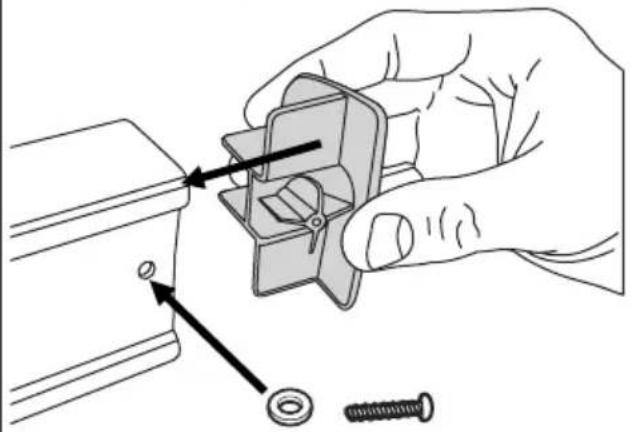
Illustration of a hand fastening a mechanical component with a screw (no text or symbols)7

natural_image
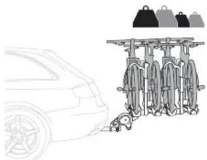
Line drawing of a car parked next to a row of bicycles with bags on top (no text or symbols)A
B
natural_image
Line drawing of a person using a bicycle tire to adjust the wheel (no text or symbols)√
natural_image
Technical line drawing of a mechanical assembly with no visible text or symbols
8

natural_image
Technical line drawing of a mechanical component with no visible text or symbols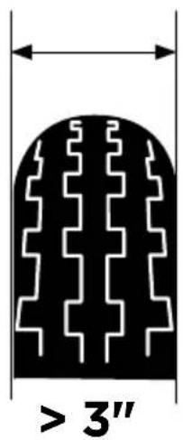
A
natural_image
Illustration of a hand using a screwdriver to adjust a component (no text or symbols present)B
natural_image
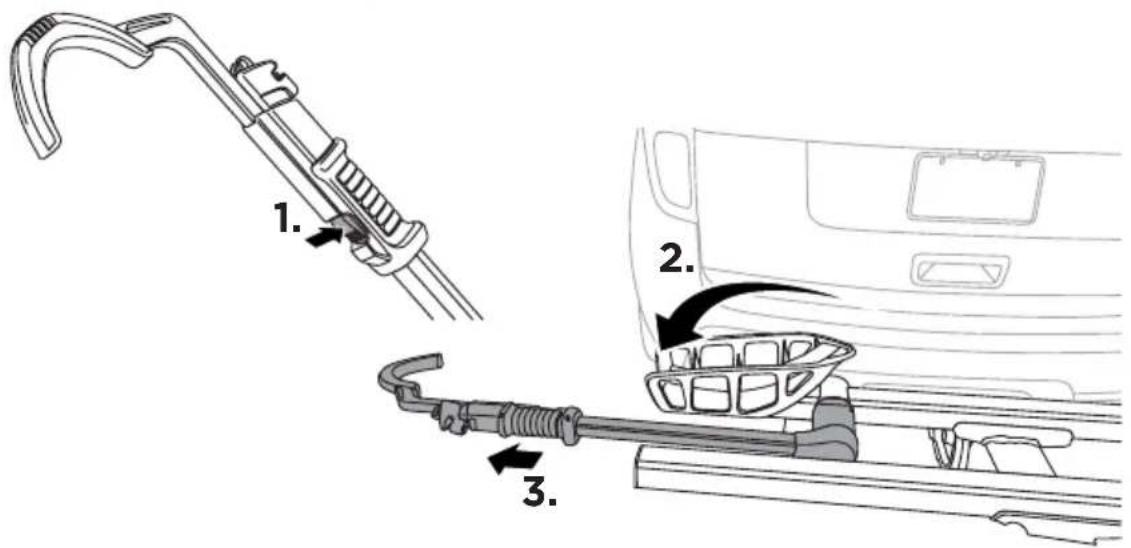
Technical line drawing of a mechanical device with a gear and handle, showing motion direction (no text or symbols)9
A
natural_image
Mechanical component diagram showing a clamp or bracket with directional arrows indicating movement (no text or symbols)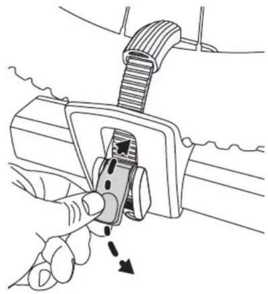
natural_image
Illustration of a hand using a tool to adjust or install a component, showing no text or symbols present.B
natural_image
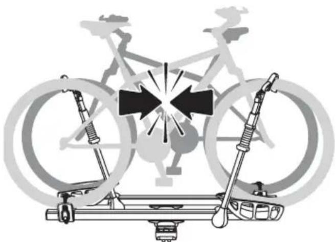
Diagram of a bicycle climbing platform with motion arrows indicating speed or movement (no text or symbols)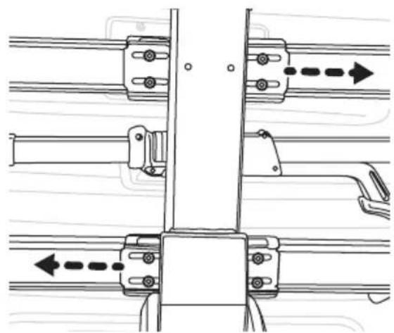
natural_image
Technical diagram of mechanical assembly with no visible text or symbols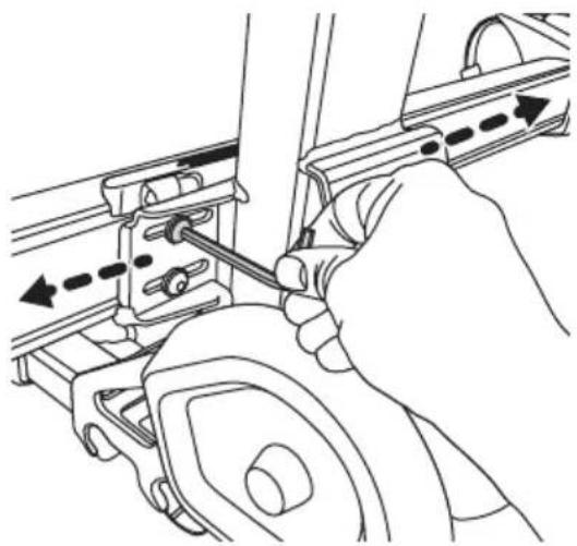
natural_image
Line drawing of a hand using a tool to adjust or install a mechanical component (no text or symbols visible)10
A
natural_image
Line drawing of a mechanical tool or device with a lever and handle (no text or symbols)B

natural_image
Illustration of a bicycle climbing rope with a key inserted, no text or symbols present
WARNING
IMPORTANT - READ CAREFULLY AND KEEP FOR FUTURE REFERENCE.
A.0 General
A.1 Thule assumes no liability for injury to persons, damage to movable or immovable property, loss of profit, or any other loss or damage caused by the improper mounting or use of the carrier, including but not limited to mounting or use in conflict with the assembly instructions, mounting instructions or any other instructions given, in writing or verbally, by Thule or a Thule dealer.
A.2 The carrier and its parts must not be modified in any way.
A.3 Consult your Thule dealer if you have any questions about the operation, use and limits of the carrier. Read all of the instructions and warranty information carefully before mounting and using the carrier.
B.O Fitting
B.1 Check the assembly instructions to make sure that all the necessary parts of the carrier are present.
B.2 Read and follow the assembly instructions and the recommendation list carefully, if the list is included. Then fit the unit in the correct sequence by following points 1, 2, 3 and so on.
B.3 Do not attempt to fit the carrier in any other way than the way shown in the mounting instructions.
C.0 Loading
C.1 The maximum load for the carrier, as specified in the assembly instructions, must not be exceeded. In addition, the maximum load recommended for the vehicle itself always takes priority over the load specified in the assembly instructions. It is always the lower recommended maximum load that applies and that must not be exceeded.
C.2 The maximum load for the carrier, as specified in the assembly instructions, applies to vehicles in motion as well as parked vehicles.
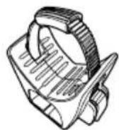
C.3 The load must be carefully secured. Elastic bungees must not be used.
C.4 Check and do not exceed the maximum weight per bike specified in the mounting instructions.
C.5 When loading bikes on the carrier, always position the largest and heaviest bikes closest to the car, followed by the smaller and lighter bikes.
C.6 The carrier is constructed to carry only standard bike frames. The carrier must not be used for tandem bikes or recumbents. Always check and do not exceed the maximum bike frame size (diameter) specified in the mounting instructions.
C.7 In the case of bikes with carbon frames or forks, always consult the bike manufacturer or dealer to check if you are allowed to use the carrier.
C.8 Thule assumes no liability for any damage to carbon frames or forks incurred during mounting and/or use of the carrier.
C.9 All easily removable parts of the bikes must be removed before transportation, including but not limited to bike covers, child seats, baskets, locks (if not permanently mounted) and air pumps. These parts can become detached during transportation because of increased air resistance and vibration and can constitute a danger to other road users.
C.10 If the vehicle is equipped with an automatic boot or tailgate opening function, this function must be disabled and the luggage compartment must be opened manually when the rear-mounted carrier is fitted, to avoid damage to the vehicle and/or the carrier.
C.11 If necessary, the load must be fitted with the appropriate lights and warning signs in accordance with local laws.
C.12 Keep the mounting and safety instructions and (if applicable) the EC-type approval in the vehicle where the carrier is mounted.
C.13 Do not install on a trailer or other towed vehicle.
D.0 Driving characteristics and regulations
D.1 This product is intended for use on public and private roads, including off-roads such as gravel roads, forest service roads, and access roads. Other off-road driving and use are made on the user's responsibility and is not covered by the warranty. Adapt your speed to the prevailing road conditions and the load being carried. Check the load fastenings regularly.
D.2 The vehicle driver is solely responsible for ensuring that the carrier is in perfect condition and that the carrier and load are securely fastened (even if fitted by a third person).
D.3 Every time the carrier is used, check that the carrier is securely fitted after driving a short distance (30 mi / 50km) and then at regular intervals. If you notice any unusual noise, movement of the load and/or carrier, different behaviour of the vehicle or other unusual conditions, stop and check that the carrier and load are secured correctly, and in accordance with the mounting instructions.
D.4 The vehicle's total length and/or height may increase when a carrier is mounted. The bikes themselves may increase the vehicle's total width and height. Take special care when reversing and/or entering garages or ferries etc.
D.5 Replace any damaged or worn parts of the carrier immediately. During transportation, all levers, bolts and/or nuts must be tightened in accordance with the mounting instructions.
D.6 Carriers fitted with a lock must always be in the locked position. The keys must be removed and kept inside the vehicle during transport.
D.7 Be aware that the vehicle's driving characteristics and braking behaviour (including in curves) might change and that the vehicle might become vulnerable to side winds when the carrier is fitted.
D.8 Depending on the carrier model, the car's tail lights can be obstructed. If that is the case and if the carrier does not already have integrated rear lights, an external light board must be fitted.
D.9 An additional number plate might be required. This should be attached to the appropriate part of the carrier in accordance with local laws.
D.10 The vehicle's speed must always be adjusted to the load being carried and the current driving conditions, such as the road type, road quality, wind conditions, traffic intensity and applicable speed limits, but must under no circumstances exceed 80 mph / 130 km/h. Applicable speed limits and other traffic regulations must always be observed.
D.11 Drive slowly over speed bumps, maximum speed 6 mph / 10 km/h.
D.12 Be aware that wind noise may be generated during transport and may vary depending on the vehicle and load.
D.13 For reasons of fuel economy and environmental impact as well as the safety of other road users, the carrier must be removed from the vehicle when not in use.
E.0 Maintenance
E.1 Clean the carrier regularly using warm water or car shampoo, especially when using or after using the carrier in coastal areas (the effect of salt water) or during periods when salt is applied to the roads (winter time).
E.2 Remove the carrier before using an automatic car wash.
E.3 Check all straps (i.e rubber-, polymer-, textile straps) for wear and replace if worn.
E.4 When the carrier is removed from the vehicle, it must be stored in a dry storage area. All the components of the carrier must be stored safely. Remember to clean and maintain the carrier in accordance with the instructions.
E.5 If you lose part(s) of the carrier or part(s) of the carrier wear out, only use genuine Thule spare parts as replacements. Spare parts can
be purchased from your dealer or manufacturer.
E.6 To ensure that you receive the spare parts quickly and to avoid time-consuming queries, please provide the relevant product details and the serial number when placing an order or making an inquiry.
E.7 In order to ensure that you are able to replace lost or defective keys as quickly as possible, note down the lock and key number which can be found on your key.
FR

AVERTISSEMENT
IMPORTANT - LISEZ ATTENTIVE- MENT CES INSTRUCTIONS ET CONSERVEZ-LES POUR RÉFÉRENCE FUTURE.
Thule Inc. 42 Silvermine Road, Seymour, CT 06483
Thule Canada Inc. 710 Bernard, Granby QC J2J 0H6
North American Consumer Service:
Toll Free 800-238-2388, Fax 450-777-3615
www.thule.com
PART OF THULE GROUP
Thule Sweden AB
Borggatan 5, 33573 Hillerstorp, SWE info@thule.com
© Thule Group. All rights reserved. 506-7248-04 | 2024-10-24 #05

Brand : THULE
Model : T2 Pro XT AddOn
Category : Bike rack