DOM392 - Air Conditioning LIVOO - Free user manual and instructions
Find the device manual for free DOM392 LIVOO in PDF.

| Product Type | Mobile air conditioner (monobloc) |
| Brand | Livoo |
| Model | DOM392 |
| Dimensions (packaged) | 480 x 360 x 850 mm |
| Weight (packaged) | 25.7 kg |
| Power supply | 220-240 V ~ 50 Hz |
| Protection class | Class I |
| Refrigerant gas | R290 (flammable) |
| Refrigerant gas quantity | 185 g |
| Cooling capacity | 9000 BTU/h (2640 W) |
| Rated power consumption (cooling) | 950 W |
| Energy class | A |
| Dehumidification capacity | 1.15 L/h |
| Airflow | 350 m³/h |
| Minimum room area | 8.9 m² (for R290) |
| Noise level (sound pressure) | 65 dB(A) |
| Noise level (sound power) | 54 dB(A) |
| Operating modes | Auto, Cooling, Dehumidification, Fan |
| Fan speed | 2 speeds (low/high) |
| Timer | Programmable on/off up to 24 h |
| Remote control | Yes (included) |
| Air filter | Washable, clean every 2 weeks/100 h |
| Filter maintenance | Vacuum or mild detergent, dry before reinstallation |
| Water tank drainage | Via bottom drain plug (error code E4) |
| Safety | Automatic shut-off when full, overcurrent protection (PCB fuse) |
| Included accessories | Exhaust hose, adapters, sliding window kit |
| Repairability | Maintenance by qualified technician (R290 gas) |
Frequently Asked Questions - DOM392 LIVOO
User questions about DOM392 LIVOO
0 question about this device. Answer the ones you know or ask your own.
Ask a new question about this device
Download the instructions for your Air Conditioning in PDF format for free! Find your manual DOM392 - LIVOO and take your electronic device back in hand. On this page are published all the documents necessary for the use of your device. DOM392 by LIVOO.
USER MANUAL DOM392 LIVOO
Climatiseur local DOM392

natural_image
Technical line drawing of a mechanical device with a 50 cm dimension label (no text or symbols on the diagram itself)Remarque
natural_image
Line drawing of a portable air conditioner unit with mesh panel and coiled tube (no text or symbols)natural_image
Illustration of a coiled tube with a circular connector (no text or symbols)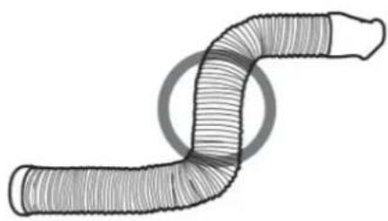
natural_image
Diagram of a worm-like structure with no text or symbolsFONCTIONNEMENT
Panneau de commande
natural_image
Line drawing of a portable air conditioner unit with ventilation grilles and control panel (no text or symbols)
Congratulations on the purchase of your new local air conditioner LIVOO. You have selected a high-quality product.
The operating instructions are a constituent part of this product. They contain important information about safety, use and disposal.
Familiarize yourself with all the operating and safety instructions before using the product.
Use the product only as described and for the stated spheres of application.
If you pass the product on to a third party, always pass on all the documentation as well.
We wish you a lot of fun with you new lacal room air conditioner LIVOO.
Intended purpose
The local air conditioner LIVOO has been designed to offer cooling, dehumidifying and fan functions.
This appliance is intended for private use and is not suitable for commercial purposes.
This appliance is designed for indoor use only.
Complies with the WEE regulation.
This product contains fluorinated greenhouse gases covered by the Kyoto protocol.
The fluorinated greenhouse gases are contained in hermetically sealed equipment.
Contents
Safety precautions 24
Meanings of the symbols 24
Safety precautions 24
Warning (if you use R290 refrigerant) 26
WEEE Warning and F-Gas instruction 30
Parts description 30
Local air conditioner 30
Remote control 31
Installation 32
Select the best location 32
Recommended installation 32
Accessories 33
Installation 33
Operation 35
Control panel 35
Operation 36
Maintenance 37
Troubleshooting 39
Specifications 40
Meanings of the symbols
Following symbols are used in the various section of this manual and on the product. Please read the user instructions carefully and respect them.

Important information or useful hints about usage.

Warning for hazardous situations with regard to life and property.

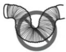
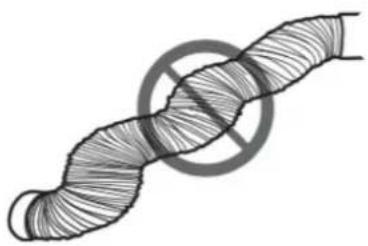
Warning to actions that must never perform.

Warning for electric shock.

This symbol shows that this appliance uses a flammable refrigerant. If the refrigerant is leaked and exposed to an external ignition source, there is a risk of fire.

Warning for hot surfaces.

Do not cover it.

This symbol shows that the operation manual should be read carefully.

This symbol shows that a service personnel should be handling this equipment with reference to the installation manual.
Safety precautions
To avoid any risk of death or personal injury to the user or any other person, or any damage to property, follow the instructions below. Improper operation due to failure to follow instructions may result in death, damage or accidents.
This appliance can be used by children aged from 8 years and above if they have been given supervision or instruction concerning use of the appliance in a safe way and understand the hazards involved. Cleaning user maintenance shall not be made by children unless they are aged from 8 years and above and supervised. Keep the
appliance and its cord out of reach of children aged less than 8 years.
This appliance is not intended for use by persons (including children) with reduced physical, sensory or mental capabilities, or lack of experience and knowledge, unless they have been given supervision or instruction concerning use of the appliance by a person
responsible for their safety. Children should be supervised to ensure that they do not play with the appliance. (except for the AC with CE-Marking)
- Incorrect installation or operation by not following these instructions may cause harm or damage to people, properties, etc.
The appliance shall be installed in accordance with national wiring regulations.
The air conditioner must be grounded. Incomplete grounding may result in electric shocks. Do not connect the earth wire to the gas pipeline, water pipeline, lightning rod, or telephone earth wire.
After installment, earth leakage examination must be carried on through electrifying.
An earth leakage breaker with rated capacity must be installed to avoid possible electric shocks.
. Don't install air conditioner in a place where there is flammable gas or liquid. It may cause fire or explosion.
. If the power supply cord is damaged, it must be replaced by the manufacture or its service agent or a similar qualified person.
The specification of the fuse are printed on the circuit bord, such as: AC 250V/5A.
. Don't put hands or any objects into the air inlets or outlets. This may cause personal injury or damage to the unit.
. Don't touch the swinging wind vanes. It may damp your finger and damage the driving parts of the wind vanes.
In lighting storm weather, please cut off the primary power supply switch in order to prevent the machine from damage.
. Don't attempt to repair the air conditioner by yourself. You may be hurt or cause further malfunctions.
Don't use liquid or corrosive detergent to clean the appliance and don't splash water or other liquid onto it, otherwise, it may damage the plastic components, even cause electric shock.
. Don't operate the unit in a wet room such as the bath room or laundry rooms.
Don't touch the unit with wet or damp hands or when barefoot.
. Don't pull the unit by the cord.
. Don't remove any part of the unit unless instructed by an authorized technician.
. Don't move the unit, unless the power has been cut off and the power cord is tied to the bending and winding column.
. Don't operate the unit with a damaged plug or a loose socket.
. Ducts connected to an appliance shall not contain an ignition source.
. Unplug before cleaning or maintenance operations.
Do not use manuals to accelerate the defrosting process or to clean, other than those recommended by the manufacturer. The appliance shall be stored in a room without continuously operation ignition sources (for example: open flames, an operation gas appliance or an operating electric heater.) Do not pierce or burn. Be aware that refrigerants may not contain an odour.
The appliance shall state the insulation of a residual current device (RCD) having rated residual operating current not exceeding 30mA.
This appliance is intended to be used in household and similar applications such as
- Staff kitchen areas in shops, offices and other working environments;
- Farmhouses;
- By clients in hotels, motels and other residential type environments;
- Bed and breakfast type environments.

WARNING
Any person who is involved with working on or breaking into a refrigerant circuit should hold a current valid certificate from an industry-accredited assessment authority, which authorises their competence to handle refrigerants safely in accordance with an industry recognised assessment specification.
Servicing shall only be performed as recommended by the equipment manufacturer. Maintenance and repair requiring the assistance of other skilled personnel shall be carried out under the supervision of the person competent in the use of flammable refrigerants.
Warning
1. Servicing
1) Checks to the area
Prior to beginning work on systems containing flammable refrigerants, safety checks are necessary to ensure that the risk of ignition is minimised. For repair to the refrigerating system, the following precautions shall be complied with prior to conducting work on the system.
2) Work procedure
Work shall be undertaken under a controlled procedure so as to minimise the risk of a flammable gas or vapour being present while the work is being performed.
3) General work area
All maintenance staff and others working in the local area shall be instructed on the nature of work being carried out. Work in confined spaces shall be avoided. The area around the workspace shall be sectioned off. Ensure that the conditions within the area have been made safe by control of flammable material.
4) Checking for presence of refrigerant
The area shall be checked with an appropriate refrigerant detector prior to and during work, to ensure the technician is aware of potentially flammable atmospheres. Ensure that the leak detection equipment being used is suitable for use with flammable refrigerants, i.e. non-sparking, adequately sealed or intrinsically safe.
5) Presence of fire extinguisher
If any hot work is to be conducted on the refrigeration equipment or any associated parts, appropriate fire extinguishing equipment shall be available to hand. Have a dry powder or CO2 fire extinguisher adjacent to the charging area.
6) No ignition sources
No person carrying out work in relation to a refrigeration system which involves exposing any pipe work that contains or has contained flammable refrigerant shall use any sources of ignition in such a manner that it may lead to the risk of fire or explosion. All possible ignition sources, including cigarette smoking, should be kept sufficiently far away from the site of installation, repairing, removing and disposal, during which flammable refrigerant can possibly be released to the surrounding space. Prior to work taking place, the area around the equipment is to be surveyed to make sure that there are no flammable hazards or ignition risks. “No Smoking” signs shall be displayed.
7) Ventilated area
Ensure that the area is in the open or that it is adequately ventilated before breaking into the system or conducting any hot work. A degree of ventilation shall continue during the period that the work is carried out. The ventilation should safely disperse any released refrigerant and preferably expel it externally into the atmosphere.
8) Checks to the refrigeration equipment
Where electrical components are being changed, they shall be fit for the purpose and to the correct specification. At all times the manufacturer's maintenance and service guidelines shall be followed. If in doubt consult the manufacturer's technical department for assistance.
The following checks shall be applied to
installations using flammable refrigerants:
- The charge size is in accordance with the room size within which the refrigerant containing parts are installed;
- The ventilation machinery and outlets are operating adequately and are not obstructed;
- If an indirect refrigerating circuit is being used, the secondary circuit shall be checked for the presence of refrigerant;
- Marking to the equipment continues to be visible and legible. Markings and signs that are illegible shall be corrected;
- Refrigeration pipe or components are installed in a position where they are unlikely to be exposed to any substance which may corrode refrigerant containing components, unless the components are constructed of materials which are inherently resistant to being corroded or are suitably protected against being so corroded.
9) Checks to electrical devices
Repair and maintenance to electrical components shall include initial safety checks and component inspection procedures. If a fault exists that could compromise safety, then no electrical supply shall be connected to the circuit until it is satisfactorily dealt with. If the fault cannot be corrected immediately but it is necessary to continue operation, an adequate temporary solution shall be used. This shall be reported to the owner of the equipment so all parties are advised. Initial safety checks shall include:
- That capacitors are discharged: this shall be done in a safe manner to avoid possibility of sparking;
- That there no live electrical components and wiring are exposed while charging, recovering or purging the system;
- That there is continuity of earth bonding.
2. Repairs to sealed components
1) During repairs to sealed components, all electrical supplies shall be disconnected from the equipment being worked upon prior to any removal of sealed covers, etc. If it
isabsolutely necessary to have an electrical supply to equipment during servicing, then a permanently operating form of leak detection shall be located at the most critical point to warn of a potentially hazardous situation.
2) Particular attention shall be paid to the following to ensure that by working on electrical components, the casing is not altered in such a way that the level of protection is affected. This shall include damage to cables, excessive number of connections, terminals not made to original specification, damage to seals, incorrect fitting of glands, etc.
Ensure that apparatus is mounted securely. Ensure that seals or sealing materials have not degraded such that they no longer serve the purpose of preventing the ingress of flammable atmospheres. Replacement parts shall be in accordance with the manufacturer's specifications.
Note
The use of silicon sealant may inhibit the effectiveness of some types of leak detection equipment. Intrinsically safe components do not have to be isolated prior to working on them.
3. Repair to intrinsically safe components
Do not apply any permanent inductive or capacitance loads to the circuit without ensuring that this will not exceed the permissible voltage and current permitted for the equipment in use. Intrinsically safe components are the only types that can be worked on while live in the presence of a flammable atmosphere. The test apparatus shall be at the correct rating. Replace components only with parts specified by the manufacturer. Other parts may result in the ignition of refrigerant in the atmosphere from a leak.
4. Cabling
Check that cabling will not be subject to wear, corrosion, excessive pressure, vibration, sharp edges or any other adverse environmental effects. The check shall also take into ccount the effects of aging or continual vibration from sources such as compressors or fans.
5. Detection of flammable refrigerants
Under no circumstances shall potential sources of ignition be used in the searching for or detection of refrigerant leaks. A halide torch (or any other detector using a naked flame) shall not be used.
6. Leak detection methods
The following leak detection methods are deemed acceptable for systems containing flammable refrigerants. Electronic leak detectors shall be used to detect flammable refrigerants, but the sensitivity may not be adequate, or may need re-calibration. (Detection equipment shall be calibrated in a refrigerant-free area.) Ensure that the detector is not a potential source of ignition and is suitable for the refrigerant used. Leak detection equipment shall be set at a percentage of the LFL of the refrigerant and shall be calibrated to the refrigerant employed and the appropriate percentage of gas (25 % maximum) is confirmed. Leak detection fluids are suitable for use with most refrigerants but the use of detergents containing chlorine shall be avoided as the chlorine may react with the refrigerant and corrode the copper pipe-work. If a leak is suspected, all naked flames shall be removed/extinguished. If a leakage of refrigerant is found which requires brazing, all of the refrigerant shall be recovered from the system, or isolated (by means of shut off valves) in a part of the system remote from the leak. Oxygen free nitrogen (OFN) shall then be purged through the system both before and during the brazing process.
7. Removal and evacuation
When breaking into the refrigerant circuit to make repairs – or for any other purpose – conventional procedures shall be used. However, it is important that best practice is followed since flammability is a consideration. The following procedure shall be adhered to:
- Remove refrigerant;
- Purge the circuit with inert gas;
- Evacuate;
- Purge again with inert gas;
- Open the circuit by cutting or brazing.
The refrigerant charge shall be recovered into the correct recovery cylinders. The system shall be “flushed” with OFN to render the unit safe. This process may need to be repeated several times. Compressed air or oxygen shall not be used for this task. Flushing shall be achieved by breaking the vacuum in the system with OFN and continuing to fill until the working pressure is achieved, then venting to atmosphere, and finally pulling down to a vacuum. This process shall be repeated until no refrigerant is within the system. When the final OFN charge is used, the system shall be vented down to atmospheric pressure to enable work to take place. This operation is absolutely vital if brazing operations on the pipework are to take place. Ensure that the outlet for the vacuum pump is not close to any ignition sources and there is ventilation available.
8. Charging procedures
In addition to conventional charging procedures, the following requirements shall be followed.
- Ensure that contamination of different refrigerants does not occur when using charging equipment. Hoses or lines shall be as short as possible to minimise the amount of refrigerant contained in them.
- Cylinders shall be kept upright.
- Ensure that the refrigeration system is earthed prior to charging the system with refrigerant.
- Label the system when charging is complete (if not already).
- Extreme care shall be taken not to overfill the refrigeration system.
Prior to recharging the system it shall be pressure tested with OFN. The system shall be leak tested on completion of charging but prior to commissioning. A follow up leak test shall be carried out prior to leaving the site.
9. Decommissioning
Before carrying out this procedure, it is essential that the technician is completely familiar with the equipment and all its detail. It is recommended good practice that all refrigerants are recovered safely. Prior to the task being carried out, an oil and refrigerant sample shall be taken in case analysis is required prior to re-use of reclaimed refrigerant. It is essential that electrical power is available before the task is commenced.
a. Become familiar with the equipment and its
Warning
operation.
b. Isolate system electrically.
c. Before attempting the procedure ensure that:
1) Mechanical handling equipment is available, if required for handling refrigerant cylinders; 2) All personal protective equipment is available and being used correctly; 3) The recovery process is supervised at all times by a competent person;
Recovery equipment and cylinders conform to the appropriate standards.
d. Pump down refrigerant system, if possible.
e. If a vacuum is not possible, make a manifold so that refrigerant can be removed from various parts of the system.
f. Make sure that cylinder is situated on the scales before recovery takes place.
g. Start the recovery machine and operate in accordance with manufacturer's instructions.
h. Do not overfill cylinders. (No more than 80 % volume liquid charge).
i. Do not exceed the maximum working pressure of the cylinder, even temporarily.
j. When the cylinders have been filled correctly and the process completed, make sure that the cylinders and the equipment are removed from site promptly and all isolation valves on the equipment are closed off.
k. Recovered refrigerant shall not be charged into another refrigeration system unless it has been cleaned and checked.
Note
The identification should be made after the appliance is scrapped and refrigerants are evacuated. The identification should contain the date and endorsement. Make sure the identification on the appliance can reflect the flammable refrigerants contained in this appliance.
10. Labelling
Equipment shall be labelled stating that it has been de-commissioned and emptied of refrigerant. The label shall be dated and signed. Ensure that there are labels on the equipment stating the equipment contains flammable
refrigerant.
11. Recovery
When removing refrigerant from a system, either for servicing or decommissioning, it is recommended good practice that all refrigerants are removed safely. When transferring refrigerant into cylinders, ensure that only appropriate refrigerant recovery cylinders are employed. Ensure that the correct number of cylinders for holding the total system charge is available. All cylinders to be used are designated for the recovered refrigerant and labelled for that refrigerant (i.e. special cylinders for the recovery of refrigerant). Cylinders shall be complete with pressure relief valve and associated shut-off valves in good working order. Empty recovery cylinders are evacuated and, if possible, cooled before recovery occurs. The recovery equipment shall be in good working order with a set of instructions concerning the equipment that is at hand and shall be suitable for the recovery of flammable refrigerants. In addition, a set of calibrated weighing scales shall be available and in good working order. Hoses shall be complete with leak-free disconnect couplings and in good condition. Before using the recovery machine, check that it is in satisfactory working order, has been properly maintained and that any associated electrical components are sealed to prevent ignition in the event of a refrigerant release. Consult manufacturer if in doubt. The recovered refrigerant shall be returned to the refrigerant supplier in the correct recovery cylinder, and the relevant Waste Transfer Note arranged. Do not mix refrigerants in recovery units and especially not in cylinders. If compressors or compressor oils are to be removed, ensure that they have been evacuated to an acceptable level to make certain that flammable refrigerant does not remain within the lubricant. The evacuation process shall be carried out prior to returning the compressor to the suppliers. Only electric heating to the compressor body shall be employed to accelerate this process. When oil is drained from a system, it shall be carried out safely.
WEEE Warning and F-Gas instruction
Meaning of crossed out wheeled dustbin: Do not dispose of electrical appliances as unsorted municipal waste, use separate collection facilities.
Contact you local government for information regarding the collection systems available. If electrical appliances are disposed of in landfills or dumps, hazardous substances can leak into the groundwater and get into the food chain, damaging your health and well-being. When replacing old appliances with new ones, the retailer is legally obligated to take back your old appliance for disposals at least
free of charge.
This product contains fluorinated greenhouse gases covered by the Kyoto protocol. The fluorinated greenhouse gases are contained in hermetically sealed equipment.
Installs, services, maintains, repairs, checks for leaks or decommissions equipment and product recycling should be carried out by natural persons that hold relevant certificates.
If the system has a leakage detection system installed, leakage checks should be performed at least every 12 months, make sure system operate properly.
If product must be performed leakage checks, it should specify Inspection cycle, establish and save records of leakage checks.
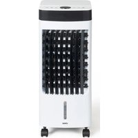
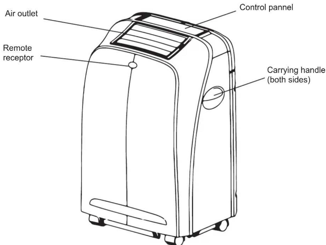
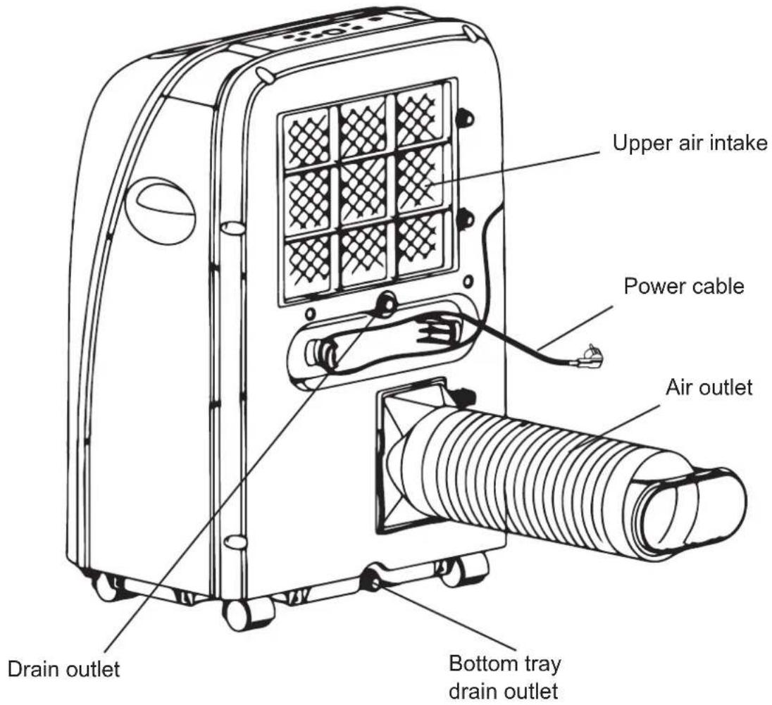
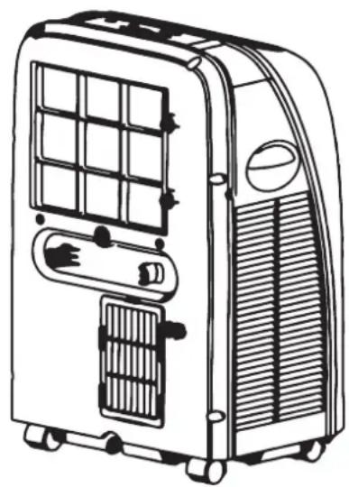
PARTS DESCRIPTION
Local air conditioner
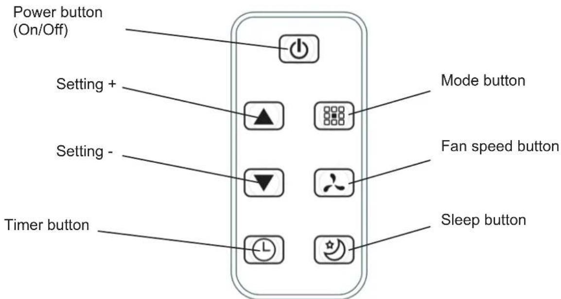
Remote control
Before using your new air conditioner, familiarize yourself in advance with its remote control. The following is a brief introduction to the remote control. For instructions on operating your air conditioner, refer to the Operation section of this manual, page 35.
INSTALLATION
Select the best location
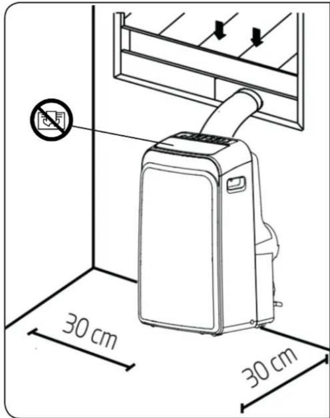
The location of your installation must meet the following requirements:
• Install the Local air conditioner in a flat and spacious location where the air outlets will not be obstructed.
- A minimum clearance of 30cm from walls or other obstacles should be kept.
- Uneven ground may cause additional noise or vibration, or lead to damage to the unit.
Recommended installation
natural_image
Technical line drawing of a mechanical device with a 50 cm dimension label (no text or symbols on the diagram itself)Note
All pictures in this manual are given only as an example. Your device may be slightly different.
The device may be controlled by the control panel on the device or with the remote control. For details, please refer to the remote control instructions supplied with this device.
Accessories
| Parts Description Quantity | ||
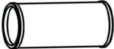 | Exhaust duct 1 pc | |
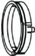 | Adaptator A (device side) 1 pc | |
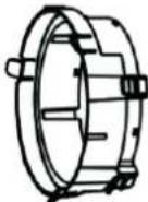 | Adaptator B (outdoor side) 1 pc | |
 | Window slider kit 1 pc |
Installation
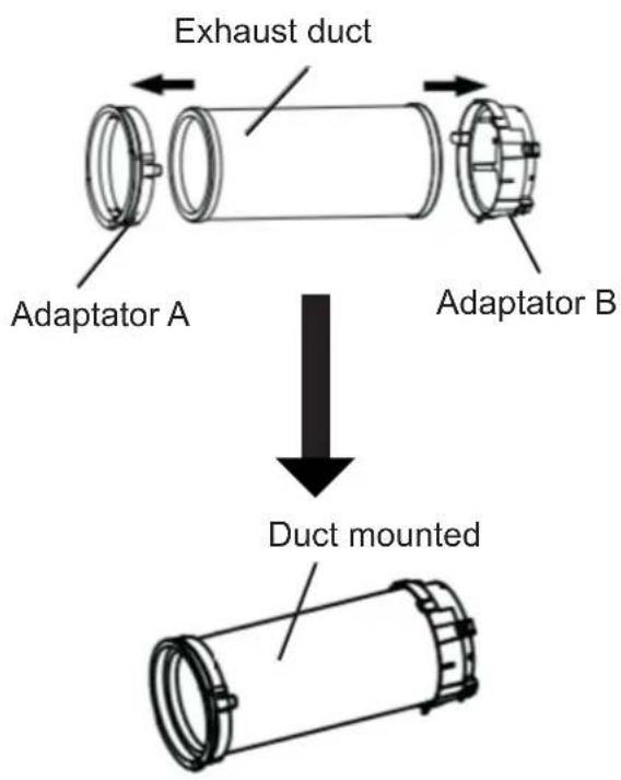 | Duct preparationConnect the duct exhaust into the adaptor of the window slider kit and secure it with the elastic loops adapters. |
natural_image
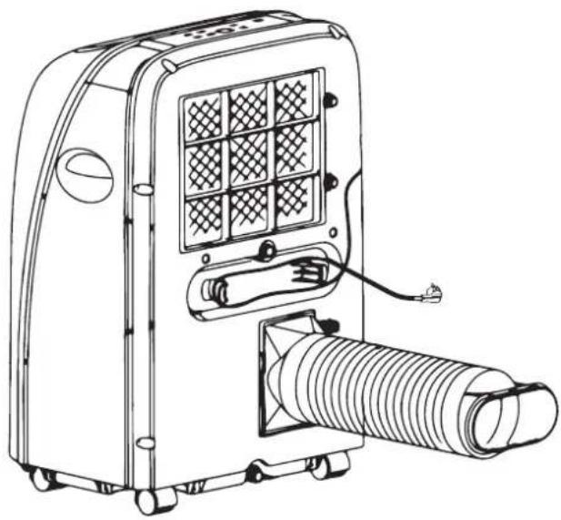
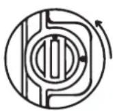
Line drawing of a portable air conditioner unit with mesh panel and coiled tube (no text or symbols)Install exhaust duct
Connect the exhaust duct to the Air outlet connector on back of the unit. Slide-in the adaptor A downwards until it is locked in place.
flowchart
graph LR
    A["A"] --> B["B"]
    B --> C[" "]
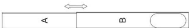
Window slider kit preparation
Adjust the length of the Window slider kit.
When the exhaust duct and window slider kit are ready, select one of these installation method to connect them.
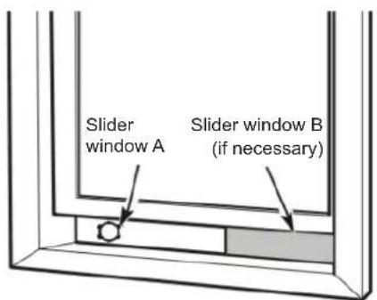
Install the window slider kit
Remove the unit with the packed exhaust duct next to the window, and then connect the adaptor of the exhaust duct with the window.
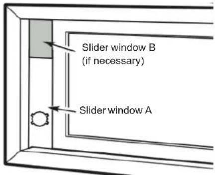
Note: Cover the hole using the adaptor cap when not in use.
Installation
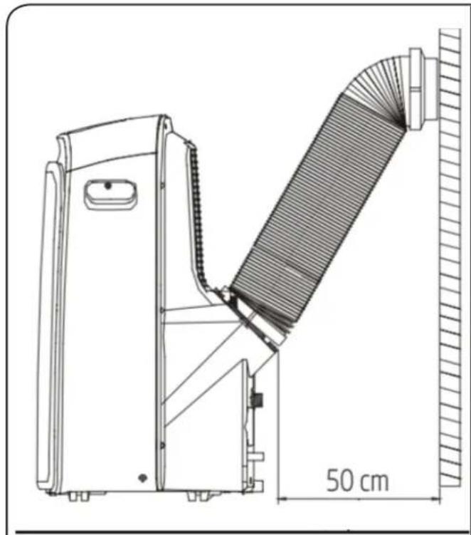
Note
To ensure proper operation, do not overtighten or bend the hose. You do not encounter any obstacles placed near the exit of the drain pipe (less than 50 cm) to ensure the optimal operation of the exhaust system.
All illustrations in this manual are for illustrative purposes only. Your air conditioner may be slightly different.
natural_image
Abstract line drawing of a coiled, elongated structure with no text or symbols
natural_image
Schematic illustration of a worm-like structure with no text or symbolsOPERATION
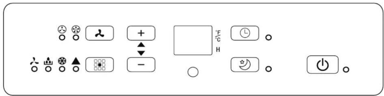
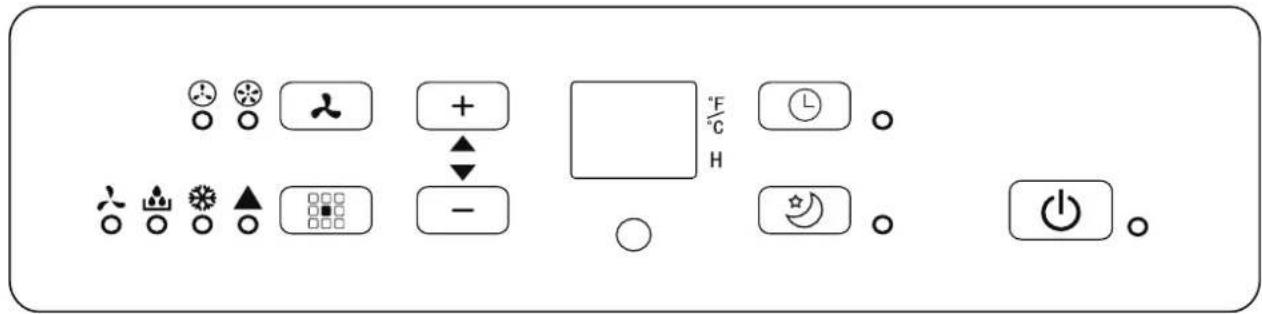
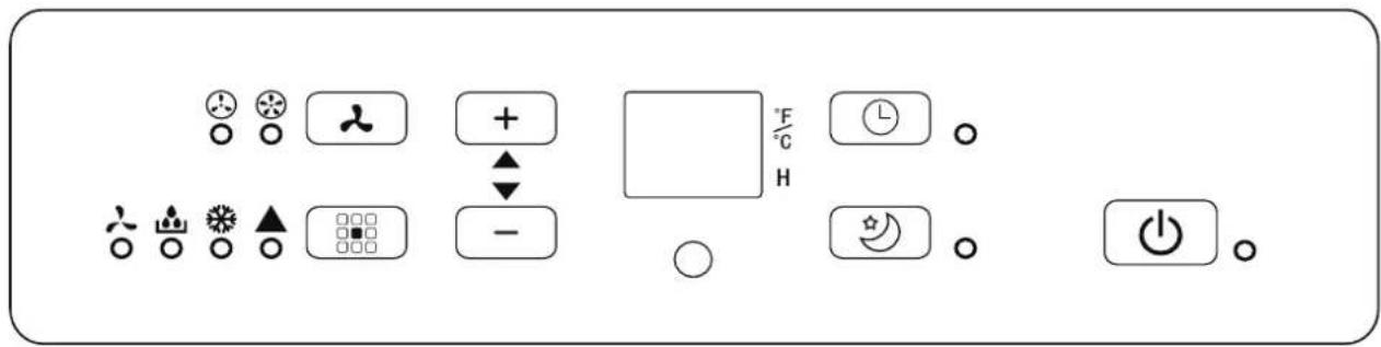
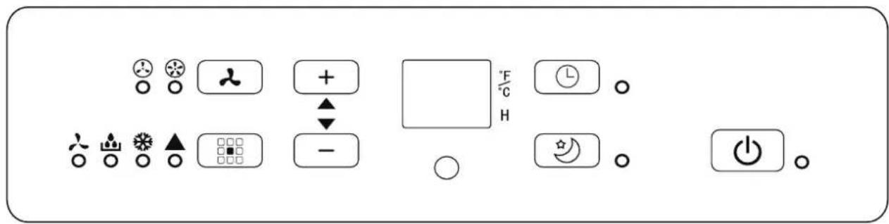
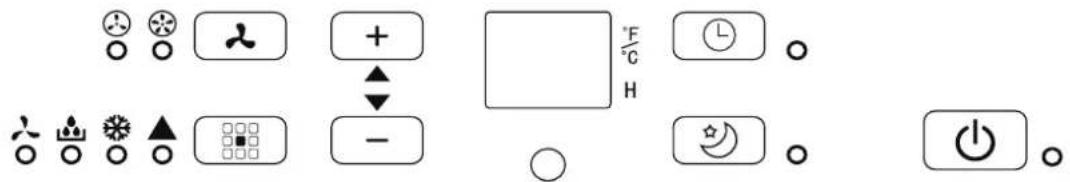
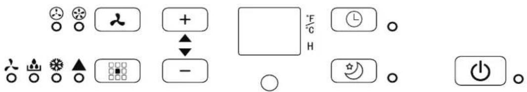
Control panel
 | On/Off Fan | Set +  |  | ||
 | Timer Mode Se |  |  | ||
 | Sleep Fan |  indicator indicator |    |
Power (ON/OFF)
Press this button to make the unit run or stop.
Timer function
Press the Timer button, the timer indicator light illuminates. Press (+) or (-) button to select the desired time. The time can be adjusted within a range of 1 hour to hour.
MODE function
Press the MODE button to select desired the running mode. Each time you press the Mode button,
Control panel
the running mode indicator light illuminates to indicate which one is selected: Auto, Cool, Dry and Fan.
Settings button (+) and (-)
Each time the + or - button is pressed, the setting temperature will increase or decrease by 1^ C. The setting temperature ranges from 15^ C - 31^ C.
Fan function
This button controls the fan speed. Press several times to select the desired fan speed, two options are available: slow and fast. The indicator for the selected fan speed lights up.
Sleep function
Press this button to enter sleep mode.
LED display
It displays the temperature set in degrees «°C» as well as the automatic timer settings. When the unit is in Dry or Fan operation mode, the display shows the room temperature.
Operation
Cooling operation mode
- Press the MODE button in a sequence until the cool indicator is lighted.
- Set the desired temperature with buttons (+) » or (-).
- Press FAN button to select the fan speed.
Drying operation mode
- Press the MODE button in a sequence until the Drying indicator is lighted.
- The setting temperature and fan speed can not be adjusted. The setting temperature and the fan speed is low.
- Close windows and doors for the best dehumidifying effect.
- Do not install the exhaust duct to the window.
Auto operation mode
- Once the "Auto" Operation is selected, The indoor temperature sensor operates automatically to select the desired operation mode with "Cooling" and "Fan"
- When the room temperature ≥ 24^ , the unit will automatically select "cooling" mode.
- When the room temperature < 24^ C , the unit will automatically select Fan mode.
Fan operation mode
- Press MODE button in a sequence until the fan indicator is lighted.
- Press the FAN button to select the fan speed.
- The setting temperature can not be adjusted.
- Do not install the exhaust duct to the window.
Timer opearation mode
- When the air conditioner is Off, press Timer button to activate the unit and set Off timer, the Off indicator light illuminates.
- Press buttons (+) and (-) to set Off timer or On time
- With the unit on, press this button to set off timer.
- With the unit off, press this button to set on timer.
Operation
Mode Sleep
- Press this button to enter sleep mode, which the unit will exit after 6 hours of continuous operation and restore to the previous status.
- The temperature will increase from 1^ after 60 minutes and 2^ after 120 minutes.
Drain water
- During dehumidifying mode, remove the upper drain plug from the back of the unit. Attach the drain hose to the hole. Place the other end of the hose in the drainage way or other drain areas.
- If the unit you bought has the pump drain outlet, as shown below, please drain in this way: Remove the pump drain plug from the back of the unit, attach the drain hose to the hole. Place the other end of the hose in the drainage way or other drain areas.
- When the water level of the bottom tray reaches predetermined level, the digital display rea shows "E4" and the WATER FULL indicator light illuminates. Carefully move the unit to a drain location, remove the bottom drain plug and let the water drain away. Reinstall the bottom drain plug and restart the machine until the E4 symbol disappears. If the error repeats, call for service.
MAINTENANCE

WARNING
- Before the cleaning of the air conditioner, it must be shut down and the electricity must be cut off for more than 5 minutes, otherwise there might be the risk of electric shocks.
- Do not use gasoline, benzene, thinner or any other chemicals, or any liquid insecticide on the air conditioner, as these substances may cause flaking off of the paint, cracking or deformation of plastic parts.
- Never attempt to clean the unit by pouring water directly over any of the surface areas, as this will cause deterioration of electrical components and wirting insulation.
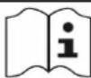
Clean the air filter
natural_image
Line drawing of a portable air conditioner unit with ventilation grilles and control panel (no text or symbols)
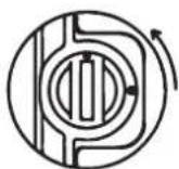
Locked / Unlocked
- Make sure the air condionner is unplugged.
- Remove the air filter. Use a vacuum cleaner or water to rinse filter, and if the filter is very dirty (for example, with greasy dirt), clean it with warm water (below 40°C) with mild detergent dissolved in, and then put the filter in the shade to dry in the air.
- Clean the air filter every 2 weeks or each 100 hours.
- Reinstall the dried filter in reverse order of removal. Put the filter cover back to its place.
Clean the unit and storage
Clean the unit
- When the unit is contaminated, clean it gently with a wrung towel using tepid water below 40°C.
Storage
- Empty the water collection tray following the instructions in the previous section.
- Run the unit in Fan mode during 12 hours in a warm room to dry and prevent mold growth.
- Turn off the device and unplug it.
- Clean the air filter according to the instructions in the previous section. Reinstall the dried and clean filter before storing the unit.
- Remove the batteries from the remote control
- Make sure to store the unit in a dark, cool place. Direct exposure to the sun or extreme heat can shorten its life.
Note
The dust on the front control panel can be removed with an oil-free cloth or washed with a cloth moistened with a solution of warm water and mild dishwashing liquid. Rinse thoroughly and wipe. Never use strong cleaners, wax or luster on the front of the unit. Make sure to wring out the cloth before wiping the control panel. Excess water in or around the control panel can damage the unit.
TROUBLESHOOTING
To save the cost of a service call, please try the suggestions below to see if you can solve your problem without outside help.
| Problem Causes solutions | ||
| Unit doesn’t start when pressing ON/OFF button | Error code «E4». | Turn off the unit and drain the condesate water. |
| Power supply is not working Check the power cable. | ||
| Unit turn off immediately. | In cooling mode: the room temperature is lower than setting temperature. | Set new temperature. |
| The exhaust duct is blocked or not install properly. | Turn off the unit and install properly the exhaust duct or clean it. | |
| The wind blowing out, but the cooling effect is bad. | The air filter is blocked by dust. | Clean the air filter. |
| Cooling capacity is insufficient. | Reconfirm the required cooling capacity with your dealer. | |
| Turn the air conditioner on in very hot room. | Allow additional time to remove stored heat from walls ,ceiling, floor and furniture. | |
| The air inlet or outlet of machine is blocked. | Remove the obstruction. | |
| The room is too big. | Reconfirm the required cooling capacity with your dealer. | |
| The doors or windows are open. | Close the doors and windows. | |
| Unit makes too much noise or vibration | The ground is not level or not flat enough. | Place the unit on a flat, level ground if possible. |
| The air filter is blocked by dust. | Clean the air filter. | |
| Water leak The bottom tray is full. | Turn off the unit and drain the condesate water. | |
Note regarding the product design
The design and specifications are subject to change without notice to improve the product. Contact the distributor or manufacturer for more information. Any update of the user manual will be uploaded to the service website. Please consult it to access the latest version.
Energy efficiency
The energy classification for this unit is based on an installation using a non-expanded exhaust duct without a sliding bay window adapter (as described in the Installation section of this manual).
Specification
| Model name DOM392 | |
| Electric class Class 1 | |
| Voltage/frequency (V/Hz) 220-240V~50Hz | |
| Refrigerant R290 | |
| Total refrigerant amount (g) 185 | |
| Cooling capacity (Btu/h) 9000 | |
| Cooling capacity (W) 2600 | |
| Cooling power input (W) 950 | |
| Rated Energy Efficiency Ratio (EERrated) 2,6 | |
| Electric consumption on Standby mode (W) 0,413 | |
| Deshumidification capacity (l/h) 1,15 | |
| Air flow volume (m3/h) 350 | |
| Sound pressure level dB(A) | LWA 65 |
| LPA 54 | |
| Energy efficiency | A |
| Unit weight - packed (kg) | 25,7 |
| Packed unit (LxHxP) mm | 480x360x850 |
| Min. applying space (m2) | 8,9 |
| Global warming potential (kgCO2eq) | 3 |
Imported by:
DELTA
BP61071
67452 Mundolsheim
France
MANUAL DEL USUARIO
¡Gracias!
natural_image
Technical line drawing of a mechanical device with a 50 cm dimension label (no text or symbols on the diagram itself)Nota
natural_image
Line drawing of a portable air conditioner unit with coiled tube and grid panel (no text or symbols)flowchart
graph LR
    A["A"] --> B["B"]
    B --> C["O"]
natural_image
Abstract line drawing of a coiled, elongated object with a circular gap and diagonal lines (no text or symbols)
natural_image
Schematic illustration of a worm-like structure with no text or symbolsOPERACIÓN
Panel de control
natural_image
Line drawing of an air conditioner unit with side and top views (no text or symbols)natural_image
Technical line drawing of a mechanical device with a 50 cm dimension label (no text or symbols on the diagram itself)Hinweis
natural_image
Line drawing of a portable air conditioner unit with mesh panel and coiled tube (no text or symbols)flowchart
graph LR
    A["A"] --> B["B"]
    B --> C["O"]
natural_image
Illustration of a coiled tube with a circular gap and a crossed-out ring (no text or symbols)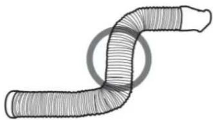
natural_image
Diagram of a coiled tube or filament with no text or symbolsBETRIEB
Bedienfeld
This button controls the fan speed. Press several times to select the desired fan speed, two options are available: slow and fast. The indicator for the selected fan speed lights up.
Funktion Ruhemodus
natural_image
Line drawing of a portable air conditioner unit with ventilation grilles and control panel (no text or symbols)
Gesperrt/Entsperrt
infiammabili Under no circumstances shall potential sources of ignition be used in the searching for or detection of refrigerant leaks. A halide torch (or any other detector using a naked flame) shall not be used.
natural_image
Technical line drawing of a mechanical device with a 50 cm dimension label (no text or symbols on the diagram itself)Nota
natural_image
Line drawing of a portable air conditioner unit with mesh panel and coiled tube (no text or symbols)flowchart
graph LR
    A["A"] --> B["B"]
    B --> C["O"]
natural_image
Abstract line drawing of a coiled, elongated object with a circular gap and crossed lines (no text or symbols)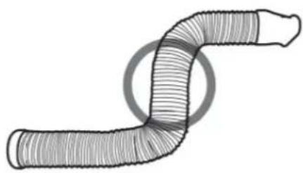
natural_image
Diagram of a worm-like structure with no text or symbolsOPERAZIONE
natural_image
Line drawing of a portable air conditioner unit with ventilation grilles and control panel (no text or symbols)
Bloccato/sbloccato
• Install the mobile air conditioner in a flat and spacious location where the air outlets will not be obstructed.
- A minimum clearance of 30cm from walls or other obstacles should be kept.
- Chão irregular pode causar ruído ou vibração adicional, ou levar a danos na unidade.
natural_image
Technical line drawing of a mechanical device with a 50 cm dimension label (no text or symbols on the diagram itself)Observação
natural_image
Line drawing of a portable air conditioner unit with coiled tube and grid panel (no text or symbols)flowchart
graph LR
    A["A"] --> B["B"]
    B --> C["O"]
natural_image
Abstract line drawing of a coiled, elongated structure with no text or symbols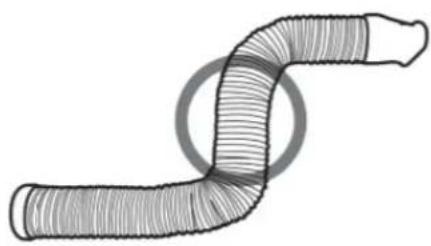
natural_image
Diagram of a coiled tube or filament with no text or symbolsOPERAÇÃO
Painel de controle
natural_image
Line drawing of an air conditioner unit with side and top views showing internal components (no text or symbols)natural_image
Technical line drawing of a mechanical device with a 50 cm dimension label (no text or symbols on the diagram itself)Opmerking
natural_image
Line drawing of a portable air conditioner unit with mesh panel and coiled tube (no text or symbols)flowchart
graph LR
    A["A"] --> B["B"]
    B --> C["O"]
natural_image
Abstract line drawing of a coiled, elongated structure with no text or symbols
natural_image
Diagram of a worm-like structure with no text or symbolsBEDIENING
Bedieningspaneel
 | Aan/Uit Ventilator  ellen - ellen - | [75TS] | ||
 | Timer Modus In  n - n - |  | ||
 | Slapen |   | Ventilatorsnelheid |    LED indicator LED indicator |
Stroom (AAN/UIT)
natural_image
Line drawing of an industrial air conditioner unit with ventilation grilles and control panel (no text or symbols)
Vergrendelt /Ontgrendeld