
CADS FLEXEO 210 - Air conditioner Soler & Palau - Free user manual and instructions
Find the device manual for free CADS FLEXEO 210 Soler & Palau in PDF.
| Product type | Double-flow heat recovery unit (MVHR) |
| Brand | Soler & Palau |
| Model | CADS FLEXEO 210 |
| Weight | 11 kg |
| Recovery efficiency | Up to 96% |
| Main function | Extraction of stale air and supply of filtered fresh air |
| Filtration | Filters on fresh air and extracted air |
| Filter maintenance | Check and clean every 6 months, replace if necessary |
| Heat exchanger maintenance | Clean every 5 years with a vacuum cleaner |
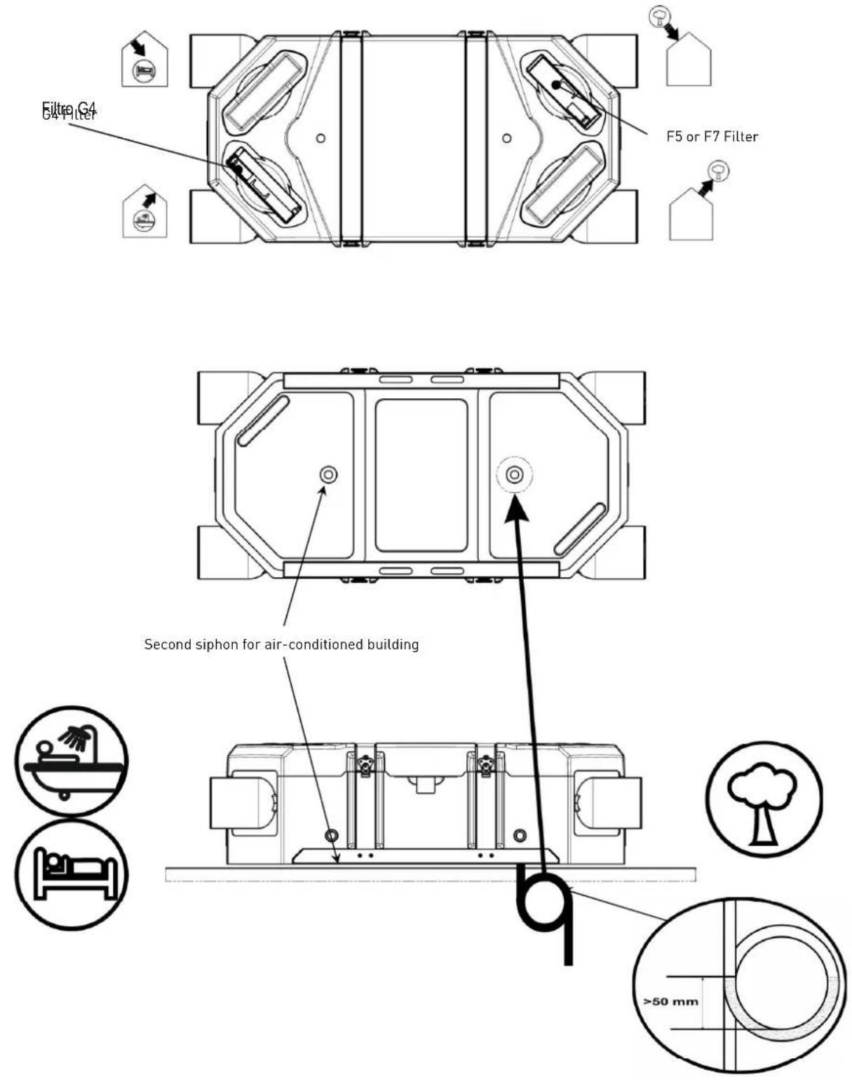
| Condensate drainage | Condensate tray to be connected to the wastewater network |
| Warranty | 3 years (free spare parts) |
| Recommended installation | In the heated space, insulated and airtight ducts |
| Compliance | EC safety directives |
| Intended use | Ventilation and air renewal of dwellings |
| Mounting type | Floor-mounted, wall-mounted, with right or left air intake |
Frequently Asked Questions - CADS FLEXEO 210 Soler & Palau
User questions about CADS FLEXEO 210 Soler & Palau
0 question about this device. Answer the ones you know or ask your own.
Ask a new question about this device
Download the instructions for your Air conditioner in PDF format for free! Find your manual CADS FLEXEO 210 - Soler & Palau and take your electronic device back in hand. On this page are published all the documents necessary for the use of your device. CADS FLEXEO 210 by Soler & Palau.
USER MANUAL CADS FLEXEO 210 Soler & Palau
natural_image
Exterior view of a black plastic mechanical device with white cylindrical ports and metallic clamps (no text or symbols visible)ESPAÑOL
natural_image
Three technical diagrams showing structural support mechanisms with cross-hatching and dimension lines (no text or symbols)natural_image
Pure technical diagram showing a cross-section of a structural component with hatched walls and a dashed line indicating a dimension (no text or symbols)Conducto aislado
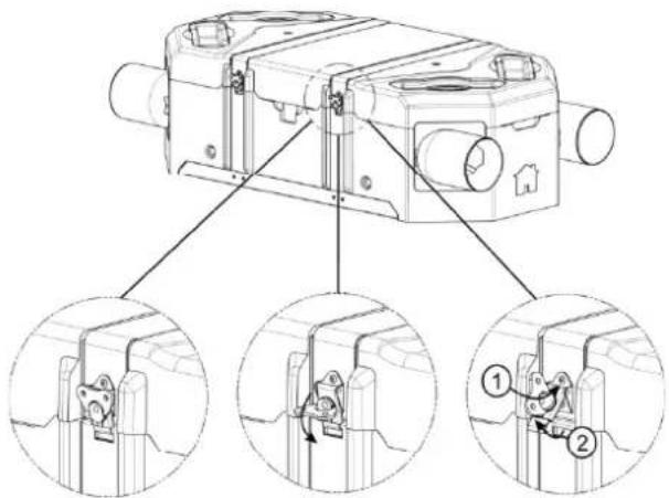
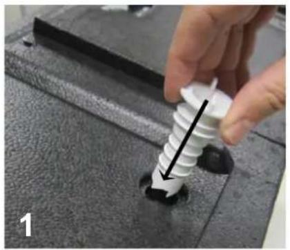
3.2. FIJACIÓN
-1-
natural_image
Technical line drawing of a mechanical housing assembly with multiple cylindrical components and mounting holes (no text or symbols)-2-
-3-
natural_image
Close-up of a hand using a white spiral screw to apply black hole onto a dark textured surface (no text or symbols visible)
natural_image
Close-up of a hand holding a white plastic screw with a black circular outline, partially inserted into a dark surface (no text or symbols visible)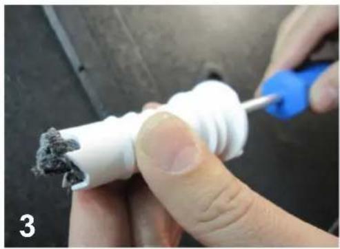
natural_image
Close-up of hands using a tool to apply material to a white plastic pipe with dark debris (no text or symbols visible)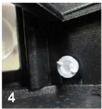
natural_image
Close-up of a mechanical component with a white cylindrical part attached, labeled '4' in the corner (no other text or symbols visible)
natural_image
Close-up of a black textured surface with a white plastic object on top, no visible text or symbols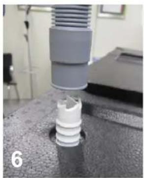
natural_image
Close-up of a mechanical component with a cylindrical base and threaded shaft, no visible text or symbols
natural_image
Close-up of a white corrugated pipe with a dark liquid at its base, placed on a textured surface (no text or symbols visible)3.4. EN EL TECHO

3.5. EN EL SUELO

natural_image
Technical line drawing of a mechanical device with two protruding ports and internal components (no text or symbols)-1-
natural_image
Technical line drawing of a mechanical device with no visible text or symbols-2-
4.2. LIMPIEZA / DESMONTAJE INTERCAMBIADOR
-1-
natural_image
Technical line drawing of a mechanical housing assembly with multiple cylindrical components and mounting holes (no text or symbols)-2-

natural_image
Technical line drawing of a mechanical assembly with no visible text or symbols-3-

natural_image
Illustration of a vacuum cleaner next to a box, no text or symbols present-4-
The CADS FLEXEO heat recovery unit is guaranteed for three years from the date of purchase. This guarantee includes free supply of spare parts.
This guarantee does not cover:
- Assembly and disassembly expenses
- Any breakdowns which according to Soler & Palau are due to poor installation, manipulation, negligence or accident.
- Any breakdowns occurring after manipulation or repair by third parties without the authorisation of Soler & Palau.
- To return a faulty part, the user should first contact the installer.
Civil Liability
The CADS FLEXEO has been designed for ventilation systems that enable the renewal of air in private homes. Soler & Palau will not be held liable for damage produced by:
- Misuse.
- Normal wear and tear of components.
- Non-observance of the instructions contained in this manual regarding safety, use and start-up.
- The use of components not supplied by Soler & Palau.
1.2. SAFETY
General safety rules
After installation, there should be no safety, health or environmental hazards, in compliance with EC regulations. This is also valid for the rest of the products used in the installation.
The following general instructions are important:
- Follow the safety instructions to avoid any damage to the fans or harm to people.
- The technical characteristics of this manual must not be modified.
• Always use the right tools. - Only use the device for the purpose it was designed for.
2. TECHNICAL INFORMATION
2.1. GENERAL DEFINITION
The CADS FLEXEO provides optimum ventilation for a room with a minimum loss of energy. It extracts air from spaces such as (Bathroom/s, WC, kitchen and washroom/s or shower room/s, and supplies fresh air into the main rooms (Living rooms, bedroom/s, office, ...). In case of offices application, the extract air and the supply fresh air could be introduced in the room.
The fresh and extracted airflows are separated and filtered. Only the energy from the extracted air is transferred to the new fresh air introduced. Due to the high efficiency exchanger of the CADS FLEXEO the performance can reach 96%.
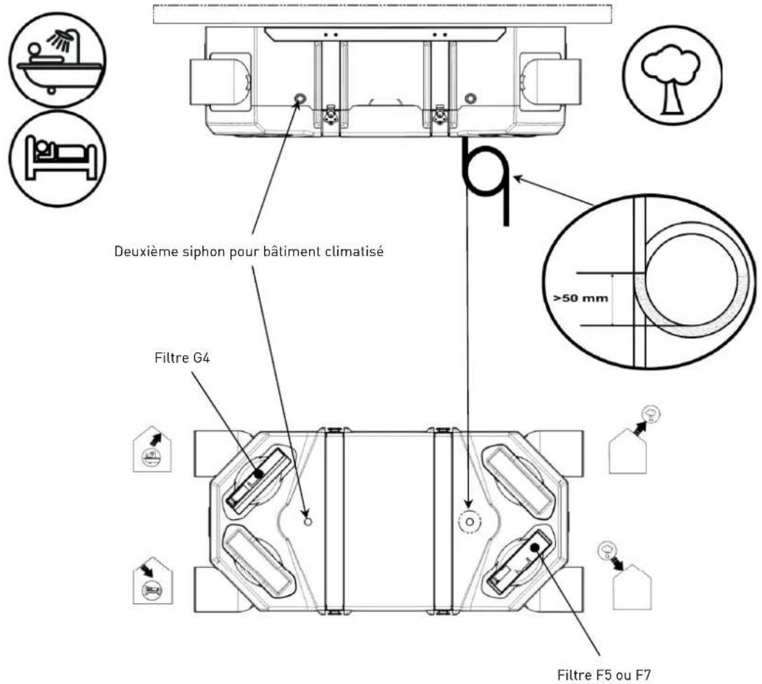
The condensation that appears at the time of exchange with the introduction of new air is collected in the condensation container, which must be connected to the drain.
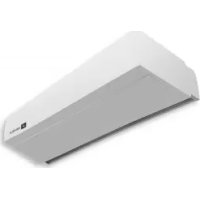
2.2. DESCRIPTION OF THE CADS FLEXEO
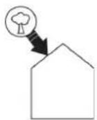
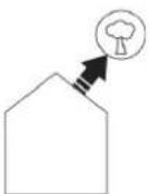
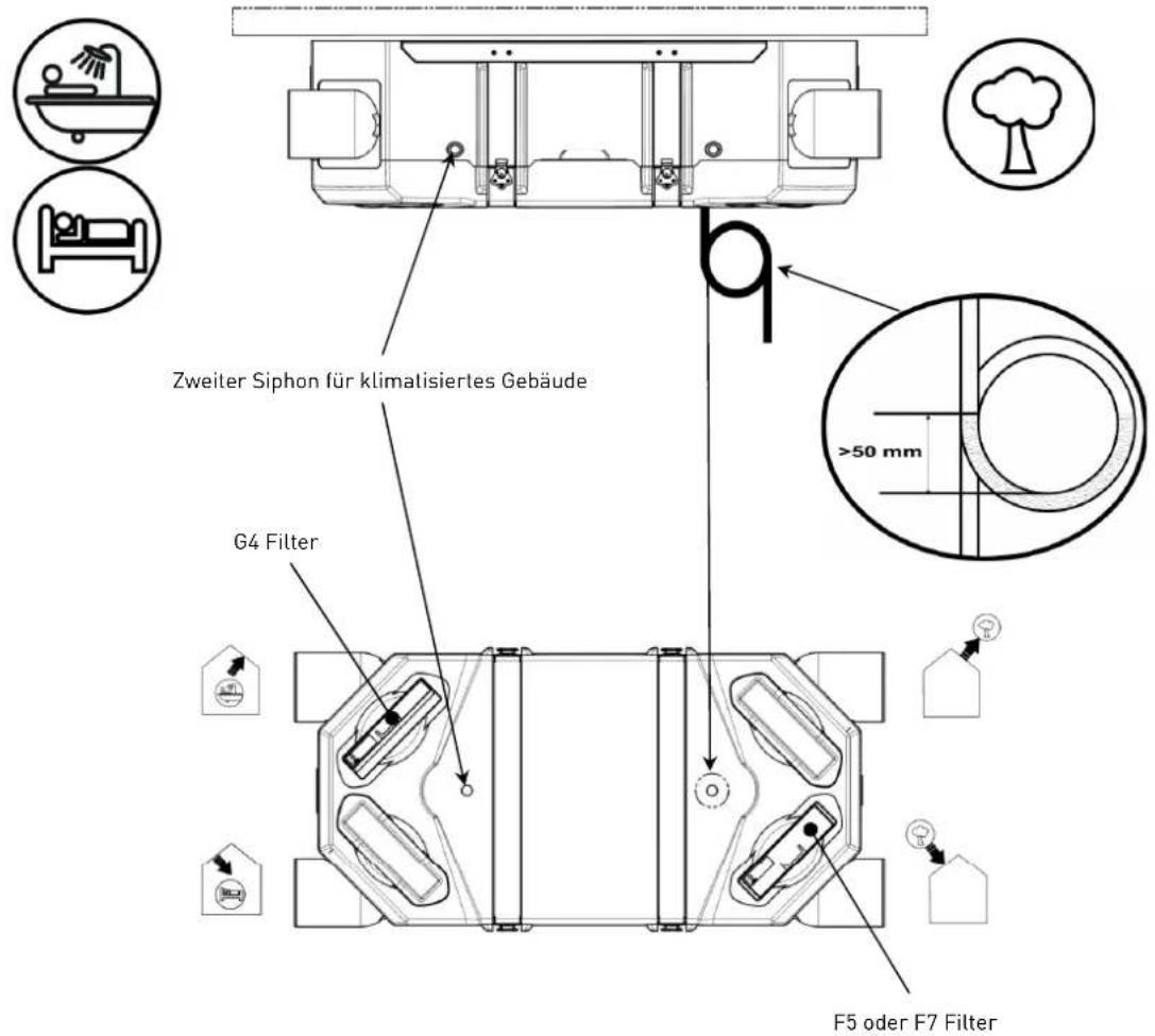
New fresh air inlet:
On this spigot is connected the outside air inlet. Be sure to position the fresh air intake (wall or roof) at a sufficient distance from any area with high pollution (Tree, rejection combustor, road, ...).
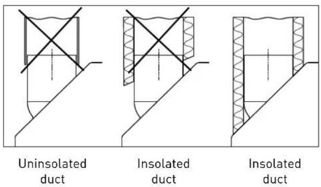
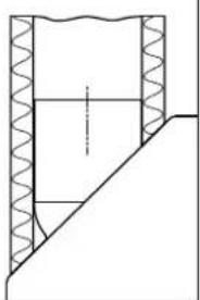
This duct should be thermally insulated and sealed to prevent condensation on the outside and inside the duct.
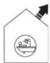
Supply fresh air into the building:
On this spigot is connected the air intake duct to the property. To avoid thermal losses, it is recommended to use insulated ducts and fitting them into the warmed volume.
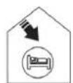
Extract air from the building:
On this spigot is connected the extract duct from the property. To avoid thermal losses and optimize the performance of the installation, it is recommended to use insulated ducts and fitting them into the warmed volume.
Discharge of extract air:
On this spigot is connected the discharge duct to the outside.
This duct should be thermally insulated and sealed to prevent condensation on the outside and inside the duct.
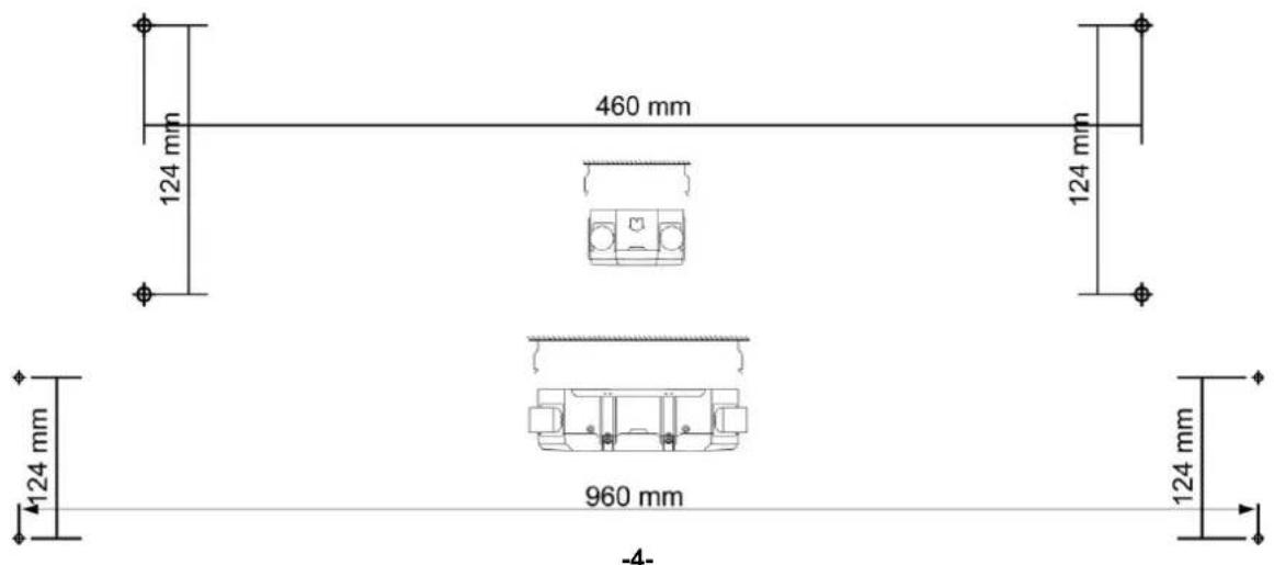
2.3. DIMENSIONAL CHARACTERISTICS
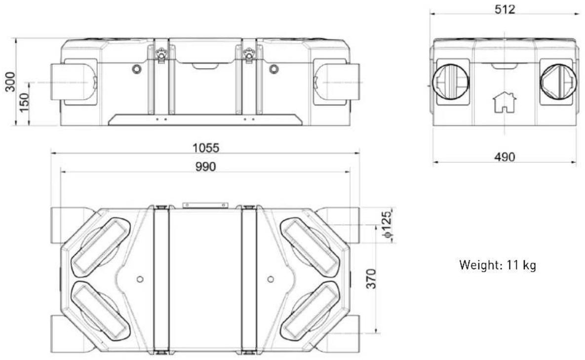
Weight: 11 kg
3. INSTALLATION
3.1. GENERAL REQUIREMENTS
- Only the fitting possibilities are described on this manual.
- The installation instructions are available with or without by-pass.
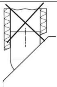
- It is recommended to install the CADS FLEXEO into the warmed house space. Otherwise, it's essential to isolate the condensate drain device.
- Ducts should be insulated and connected perfectly. The insulation must completely cover the spigot as below.
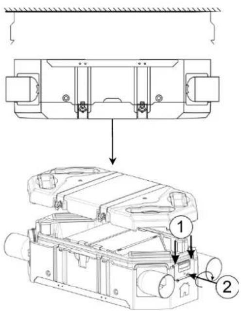
3.2. FITTING
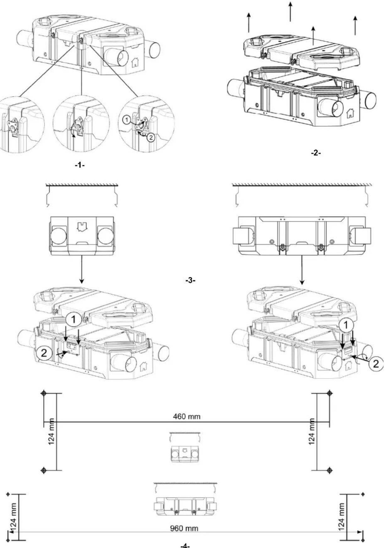
Use the template on the packaging
3.3. INSTALLATION AND CONNECTION OF THE DRAIN DEVICE
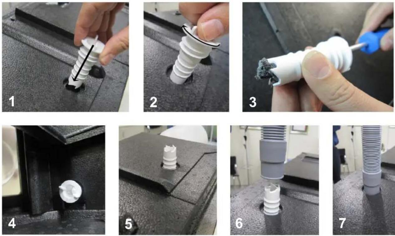

natural_image
Close-up of a cylindrical tube inserted into a textured surface, no visible text or symbols3.4. CEILING MOUNTING

3.5. ON THE FLOOR
3.6. ON THE WALL HORIZONTAL MOUNTING
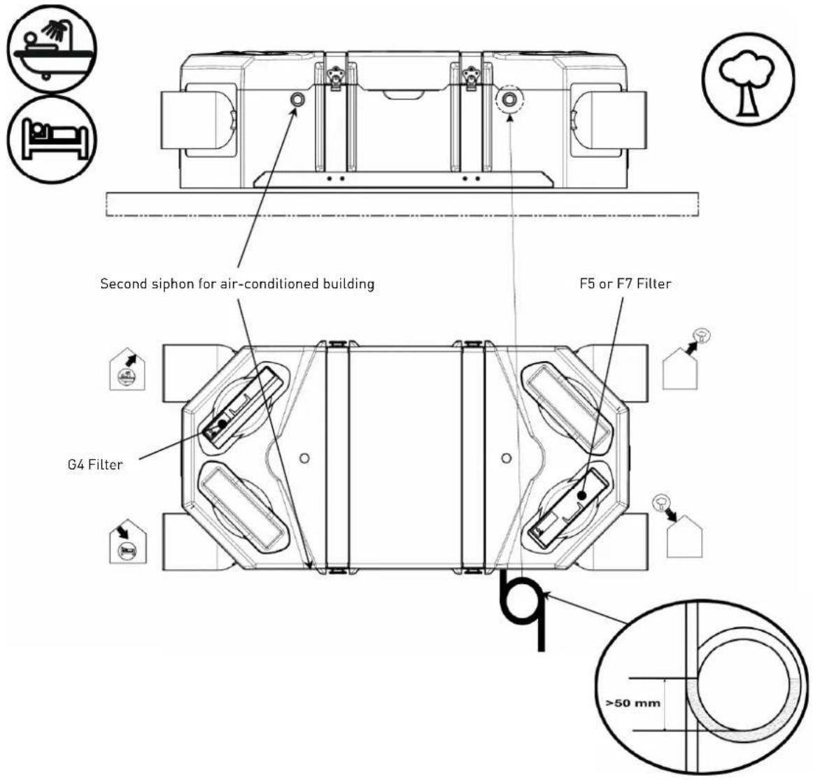
3.6.a. Fresh intake air on the right
3.6.b. Fresh intake air on the left
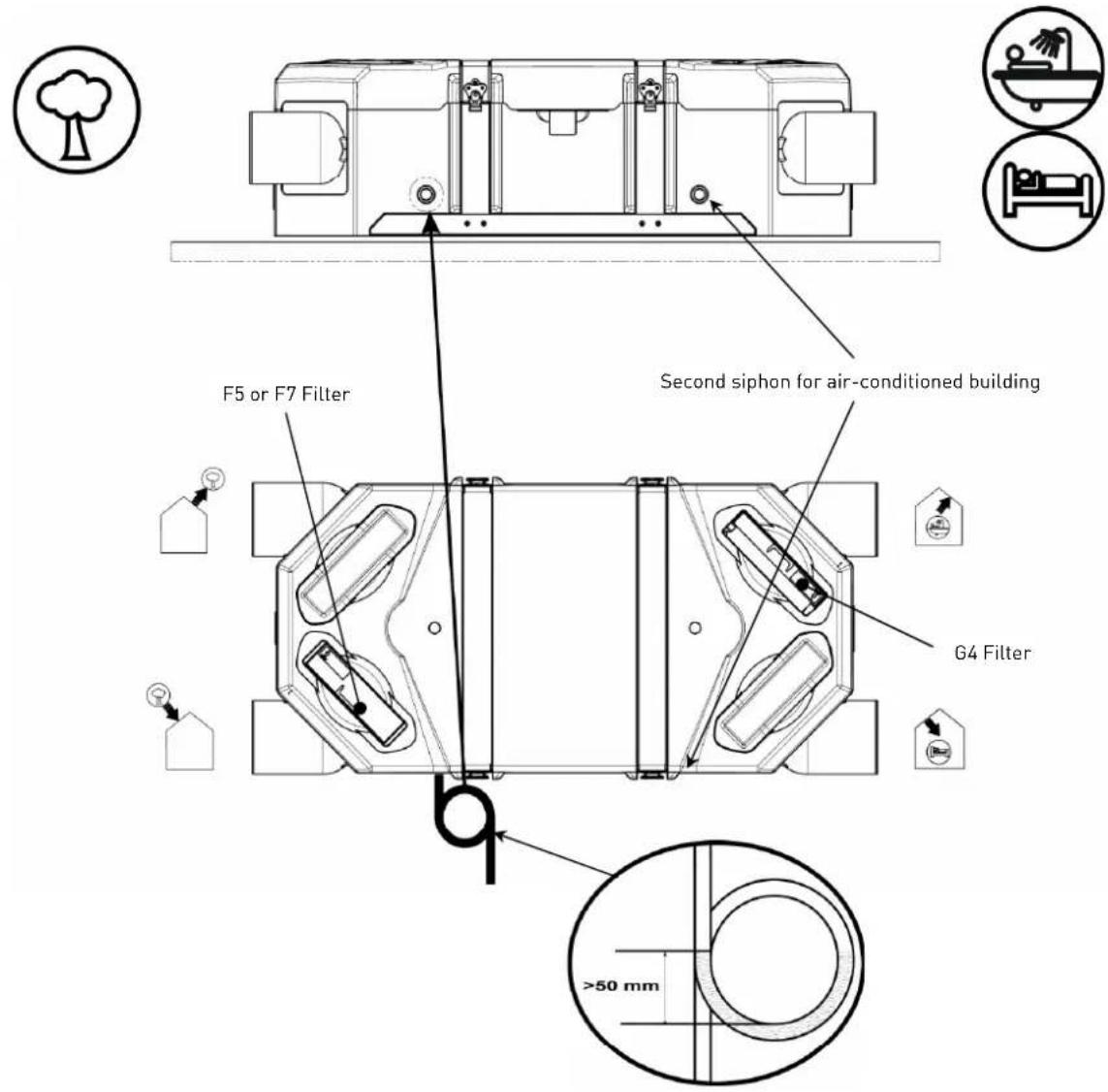
3.7. ON THE WALL - VERTICAL MOUNTING - FRESH INTAKE AIR ON THE RIGHT
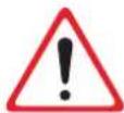
Not allowed assembly in an air condicioned building
3.8. EXAMPLE OF FITTING "SPLIT" TYPE
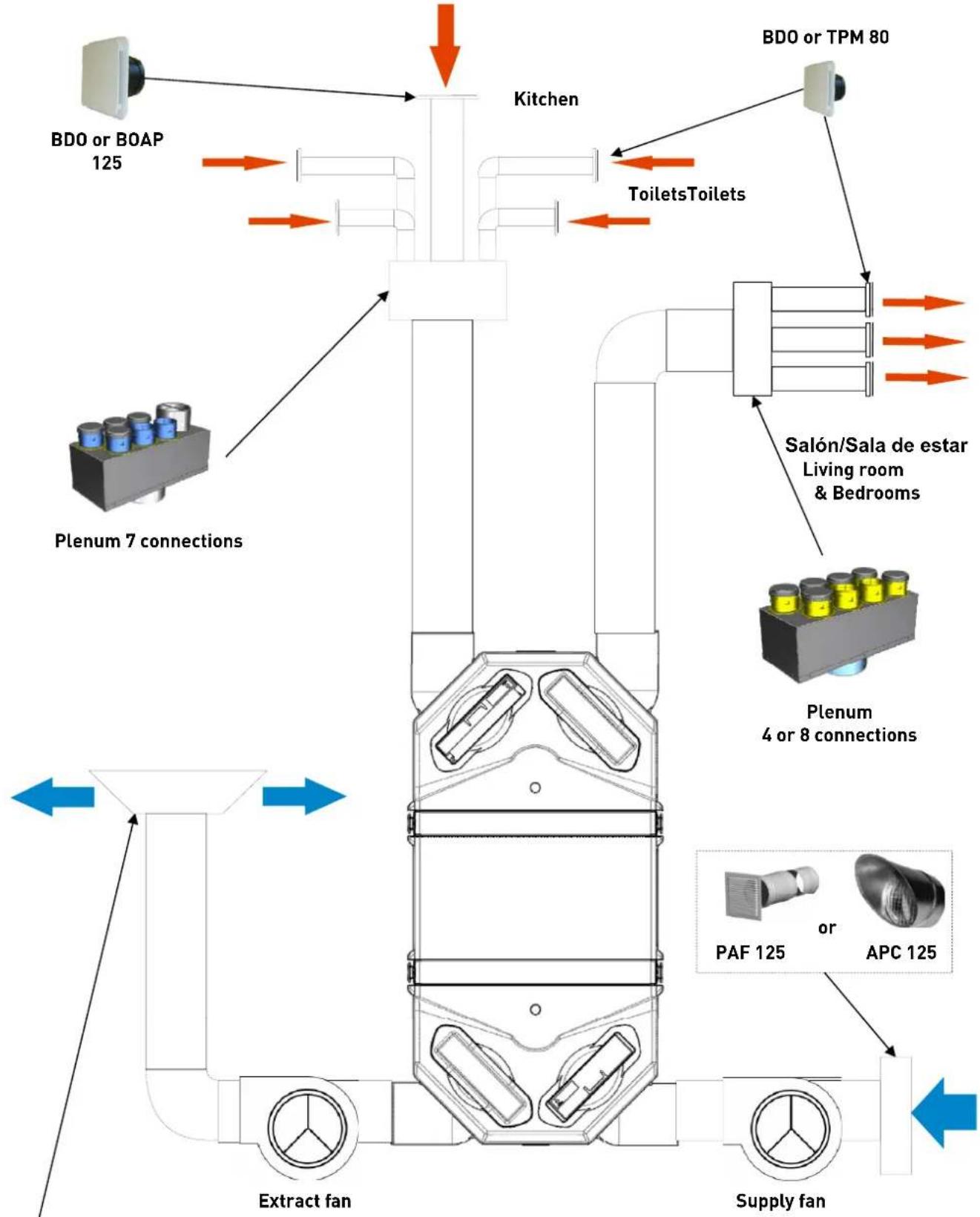
flowchart
graph TD
    A["Supply fan"] --> B["Extract fan"]
    B --> C["Plenum 7 connections"]
    C --> D["ToiletsToilets"]
    D --> E["Kitchen"]
    E --> F["BDO or BOAP 125"]
    E --> G["BDO or TPM 80"]
    E --> H["Salón/Sala de estar Living room & Bedrooms"]
    E --> I["Plenum 4 or 8 connections"]
    I --> J["APC 125"]
    I --> K["PAF 125"]
    style A fill:#f9f,stroke:#333
    style B fill:#ccf,stroke:#333
    style C fill:#cfc,stroke:#333
    style D fill:#fcc,stroke:#333
    style E fill:#cff,stroke:#333
    style F fill:#ffc,stroke:#333
    style G fill:#ffc,stroke:#333
    style H fill:#ffc,stroke:#333
    style I fill:#cfc,stroke:#333
    style J fill:#cfc,stroke:#333
    style K fill:#cfc,stroke:#333
In the case of use of flexible duct insulated, it is imperative to stretch it.
3.9. EXAMPLE OF FITTING "DISTRIBUTION" TYPE
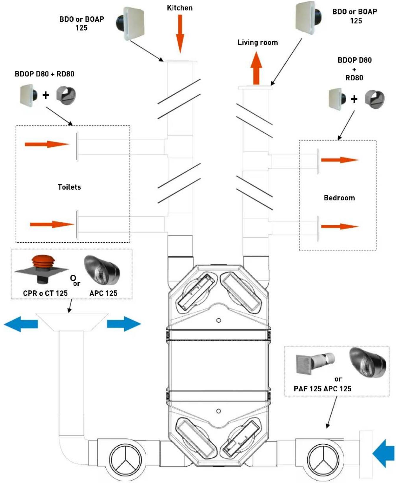
flowchart
graph TD
    A["Apartment"] --> B["Apartment"]
    B --> C["Apartment"]
    C --> D["Apartment"]
    D --> E["Apartment"]
    E --> F["Apartment"]
    F --> G["Apartment"]
    G --> H["Apartment"]
    H --> I["Apartment"]
    I --> J["Apartment"]
    J --> K["Apartment"]
    K --> L["Apartment"]
    L --> M["Apartment"]
    M --> N["Apartment"]
    N --> O["Apartment"]
    O --> P["Apartment"]
    P --> Q["Apartment"]
    Q --> R["Apartment"]
    R --> S["Apartment"]
    S --> T["Apartment"]
    T --> U["Apartment"]
    U --> V["Apartment"]
    V --> W["Apartment"]
    W --> X["Apartment"]
    X --> Y["Apartment"]
    Y --> Z["Apartment"]
    Z --> AA["Apartment"]
    AA --> AB["Apartment"]
    AB --> AC["Apartment"]
    AC --> AD["Apartment"]
    AD --> AE["Apartment"]
    AE --> AF["Apartment"]
    AF --> AG["Apartment"]
    AG --> AH["Apartment"]
    AH --> AI["Apartment"]
    AI --> AJ["Apartment"]
    AJ --> AK["Apartment"]
    AK --> AL["Apartment"]
    AL --> AM["Apartment"]
    AM --> AN["Apartment"]
In the case of use of flexible duct insulated, it is imperative to stretch it.
4. MAINTENANCE
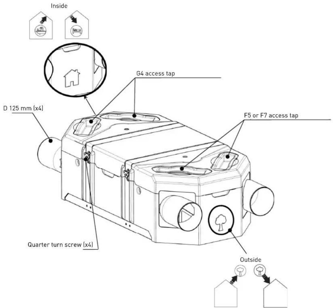
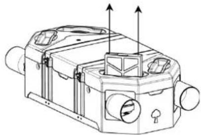
4.1. CHANGING FILTERS
Check, clean or change if necessary filters each 6 moths.
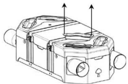
natural_image
Technical line drawing of a mechanical device with ports and mounting holes (no text or symbols)-1-

natural_image
Technical line drawing of a mechanical device with no visible text or symbols-2-
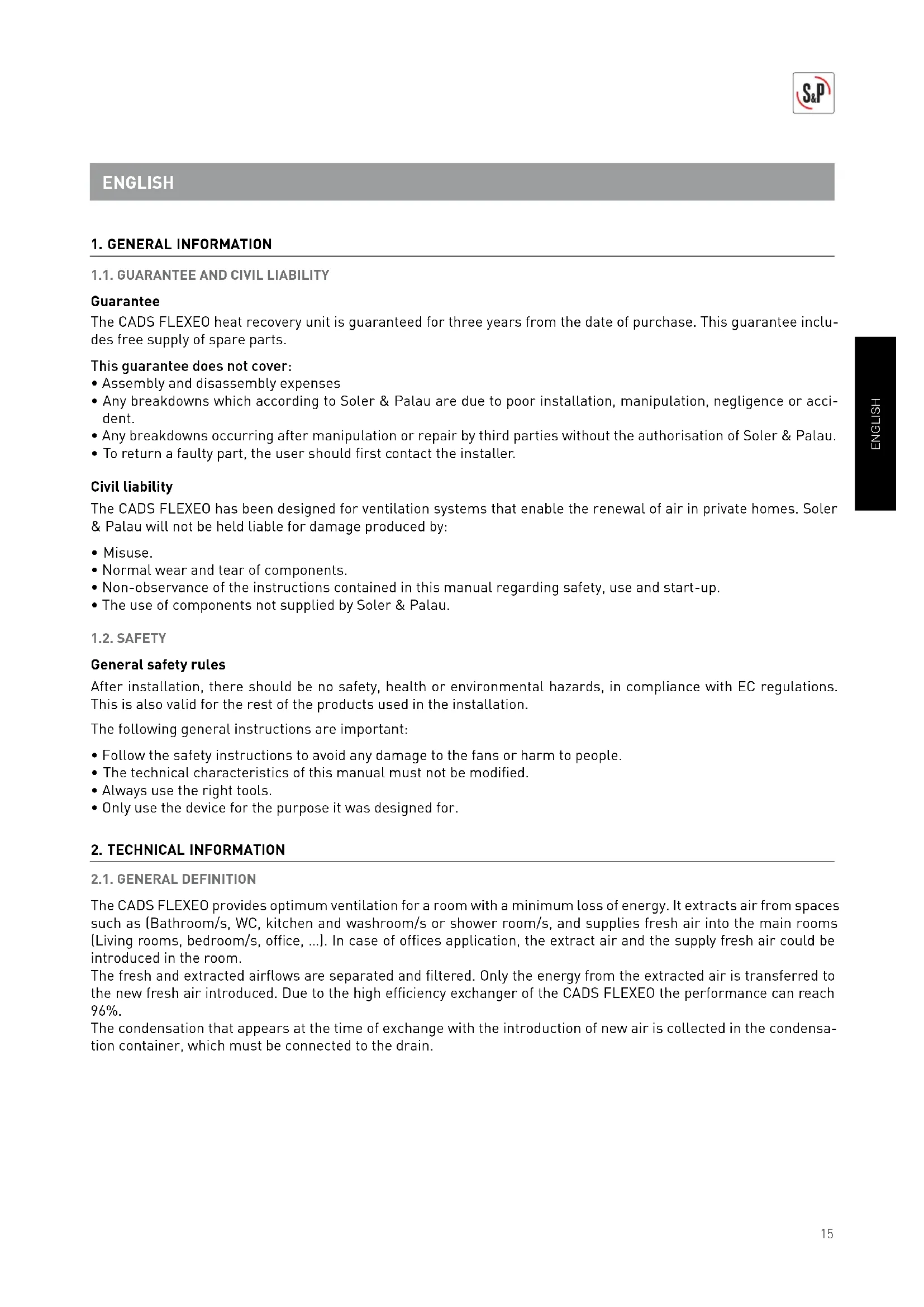
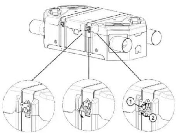
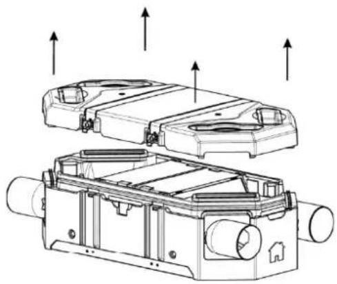
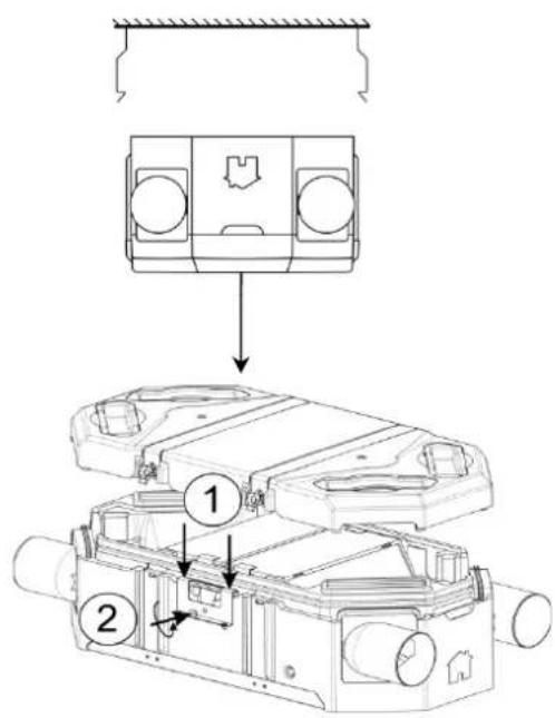
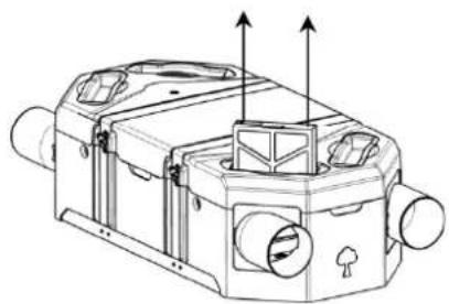
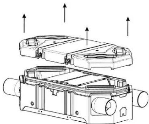
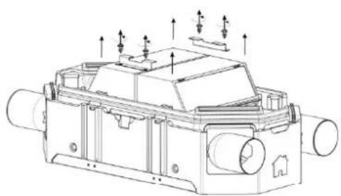
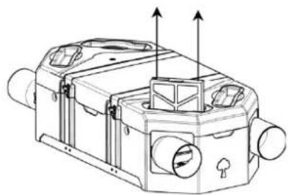
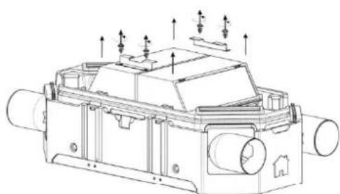
4.2. CLEANING/REMOVING HEAT EXCHANGER
Check and clean if necessary the heat exchanger each 5 years.
-1-

natural_image
Technical line drawing of a mechanical housing assembly with multiple cylindrical components and mounting holes (no text or symbols)-2-

natural_image
Technical line drawing of a mechanical assembly with no visible text or symbols-3-

natural_image
Illustration of a vacuum cleaner emitting a blue cable, next to a white box (no text or symbols)-4-
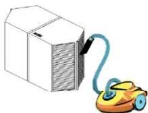
Use a domestic vacuum to aspirate the 4 sides of the heat exchanger.
FRANÇAIS
1. INFORMATION GÉNÉRALE
1.1. GARANTIE ET RESPONSABILITÉ CIVILE
Garantie
natural_image
Three technical diagrams showing structural support mechanisms with cross-hatching and alignment lines (no text or symbols)Conduit non isolé
natural_image
Pure mechanical cross-section diagram without any text, numbers, or symbolsConduit isolé
natural_image
Pure technical diagram showing a cross-section of a layered structure with hatched walls and a diagonal line (no text or symbols)Conduit isolé
natural_image
Close-up of a hand holding a white spiral screw with a black arrow pointing to a hole, against a dark textured surface (no text or symbols visible)
natural_image
Close-up of a hand holding a white plastic screw with a black curved line marking the tip, against a dark textured surface (no text or symbols visible)
natural_image
Close-up of hands using a tool to apply material to a white plastic component (no visible text or symbols)
natural_image
Close-up of a white plastic component mounted on a black mechanical base, with no visible text or symbols.
natural_image
Close-up of a black textured surface with a small white cylindrical object on top, labeled '5' in the corner (no other text or symbols)
natural_image
Close-up of a mechanical testing setup with a cylindrical component mounted on a textured surface (no visible text or symbols)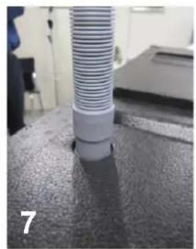
natural_image
Close-up of a cylindrical tube inserted into a textured surface, no visible text or symbols3.4. MONTAGE PLAFOND
natural_image
Technical line drawing of a mechanical device with two ports and directional arrows indicating flow or movement (no text or symbols present)-1-

natural_image
Technical line drawing of a mechanical device with no visible text or symbols-2-
4.2. NETTOYAGE / DÉMONTAGE ÉCHANGEUR
-1-

natural_image
Technical line drawing of a mechanical housing assembly with multiple cylindrical components and mounting holes (no text or symbols)-2-
natural_image
Technical line drawing of a mechanical device with multiple ports and mounting features (no text or symbols)-3-

natural_image
Illustration of a vacuum cleaner connected to a box (no text or symbols)-4-
natural_image
Close-up of a hand holding a white spiral screw with a black arrow pointing to a hole, against a dark textured surface (no text or symbols visible)
natural_image
Close-up of a hand holding a white plastic screw with a black outline, inserted into a dark surface (no text or symbols visible)
natural_image
Close-up of hands using a tool to apply material to a white plastic component with a dark substance (no text or symbols visible)
natural_image
Close-up of a white plastic component mounted on a black mechanical base, with no visible text or symbols.
natural_image
Close-up of a black textured surface with a small white cylindrical object on top, labeled '5' in the corner (no other text or symbols)
natural_image
Close-up of a mechanical testing setup with a cylindrical component mounted on a textured surface (no visible text or symbols)
natural_image
Close-up of a cylindrical tube inserted into a textured surface, no visible text or symbols3.4. MONTAGGIO A SOFFITTO

natural_image
Technical line drawing of a mechanical housing component with mounting holes and internal components (no text or symbols)-1-
natural_image
Technical line drawing of a mechanical device with ports and directional arrows (no text or symbols)-2-
4.2. PULIZIA / RIMOZIONE DELLO SCAMBIATORE DI CALORE
-1-

natural_image
Technical line drawing of a mechanical housing assembly with multiple cylindrical components and mounting holes (no text or symbols)-2-
natural_image
Technical line drawing of a mechanical assembly with no visible text or symbols-3-
natural_image
Illustration of a vacuum cleaner next to a box, no text or symbols present-4-
natural_image
Close-up of a hand holding a white spiral screw with a black arrow pointing to a hole, against a dark textured surface (no text or symbols visible)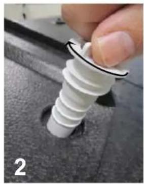
natural_image
Close-up of a hand holding a white plastic screw with a black outline, inserted into a dark surface (no text or symbols visible)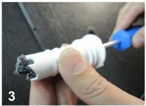
natural_image
Close-up of hands using a tool to apply material to a white plastic component with a dark substance (no text or symbols visible)
natural_image
Close-up of a white plastic component mounted on a black mechanical base, with no visible text or symbols.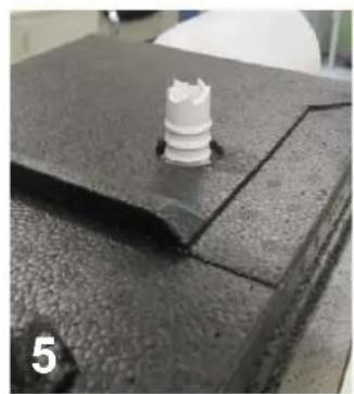
natural_image
Close-up of a black textured surface with a small white cylindrical object on top, labeled '5' in the corner (no other text or symbols)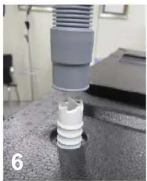
natural_image
Close-up of a mechanical testing setup with a cylindrical component mounted on a textured surface (no visible text or symbols)
natural_image
Close-up of a cylindrical tube inserted into a textured surface, no visible text or symbols3.4. DECKENMONTAGE
natural_image
Technical line drawing of a mechanical housing component with mounting holes and internal components (no text or symbols)-1-
natural_image
Technical line drawing of a mechanical device with ports and directional arrows (no text or symbols)-2-
-1-

natural_image
Technical line drawing of a mechanical housing assembly with multiple cylindrical components and mounting holes (no text or symbols)-2-

natural_image
Technical line drawing of a mechanical assembly with no visible text or symbols-3-

natural_image
Illustration of a compact box connected to a yellow spray gun (no text or symbols)-4-
natural_image
Pure technical diagram showing a cross-section of a structural component with no text or symbolsnatural_image
Pure mechanical cross-section diagram without any text, numbers, or symbolsnatural_image
Pure technical diagram showing a cross-section of a structural component with hatched walls and a dashed line indicating a dimension (no text or symbols)3.3. INSTALLATIE EN AANSLUITING VAN HET AFVOERAPPARAAT
natural_image
Close-up of a hand holding a white spiral screw with a black arrow pointing to a hole, against a dark textured surface (no text or symbols visible)
natural_image
Close-up of a hand holding a white plastic screw with a black curved line marking the tip, against a dark textured surface (no text or symbols visible)
natural_image
Close-up of hands using a tool to apply material to a white plastic component (no visible text or symbols)
natural_image
Close-up of a white plastic component mounted on a black mechanical base, with no visible text or symbols.
natural_image
Close-up of a black textured surface with a small white cylindrical object on top, labeled '5' in the corner (no other text or symbols)
natural_image
Close-up of a mechanical testing setup with a cylindrical component mounted on a textured surface (no visible text or symbols)
natural_image
Close-up of a cylindrical tube inserted into a textured surface, no visible text or symbols3.4. PLAFONDMONTAGE

natural_image
Technical line drawing of a mechanical housing component with mounting holes and internal components (no text or symbols)-1-

natural_image
Technical line drawing of a mechanical device with ports and directional arrows (no text or symbols)-2-
4.2. WARMWTTE-UITITWIISSELLAAR REINIIIGEN / DEMONDTTEREN
-1-

natural_image
Technical line drawing of a mechanical housing assembly with multiple cylindrical components and mounting holes (no text or symbols)-2-

natural_image
Technical line drawing of a mechanical assembly with no visible text or symbols-3-

natural_image
Illustration of a white box connected to a yellow and blue handheld device (no text or symbols)-4-
- ESPAÑOL
- LIMPIEZA / DESMONTAJE INTERCAMBIADOR
- This guarantee does not cover:
- Civil Liability
- SAFETY
- General safety rules
- TECHNICAL INFORMATION
- GENERAL DEFINITION
- DESCRIPTION OF THE CADS FLEXEO
- New fresh air inlet:
- Supply fresh air into the building:
- Extract air from the building:
- Discharge of extract air:
- INSTALLATION
- GENERAL REQUIREMENTS
- ON THE WALL HORIZONTAL MOUNTING
- 3.6.a. Fresh intake air on the right
- 3.6.b. Fresh intake air on the left
- ON THE WALL - VERTICAL MOUNTING - FRESH INTAKE AIR ON THE RIGHT
- MAINTENANCE
- CHANGING FILTERS
- CLEANING/REMOVING HEAT EXCHANGER
- FRANÇAIS
- INFORMATION GÉNÉRALE
- GARANTIE ET RESPONSABILITÉ CIVILE
- Garantie
- NETTOYAGE / DÉMONTAGE ÉCHANGEUR
- PULIZIA / RIMOZIONE DELLO SCAMBIATORE DI CALORE
- WARMWTTE-UITITWIISSELLAAR REINIIIGEN / DEMONDTTEREN
Brand : Soler & Palau
Model : CADS FLEXEO 210
Category : Air conditioner