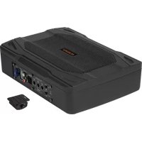
MW1000A - Subwoofer Musway - Free user manual and instructions
Find the device manual for free MW1000A Musway in PDF.

| Product type | Active subwoofer |
| Brand | Musway |
| Model | MW1000A |
| Speaker diameter | 28 cm (11 inches) |
| RMS output power | 1 x 150 W |
| Maximum output power | 1 x 300 W |
| Frequency range | 20 - 150 Hz |
| Adjustable low-pass filter | 50 - 150 Hz |
| Subsonic filter | Fixed at 20 Hz |
| Phase shift | 0° / 180° |
| Bass boost | 0 - 12 dB @ 45 Hz |
| Supply voltage | 12 V (9 - 15 V), negative ground |
| Fuse | 25 A (replaceable) |
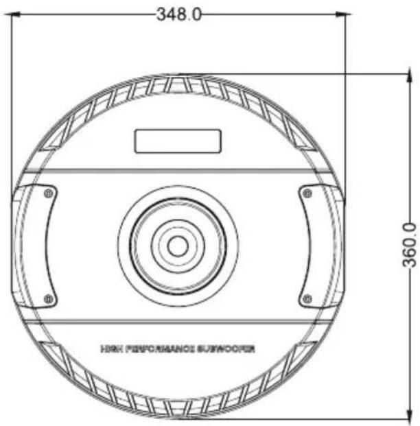
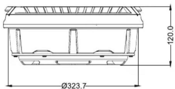
| Dimensions (diameter x height) | Ø 360 x 120 mm |
| Protection circuit | Green LED (on), Red LED (overheat/short circuit) |
| Adjustable input sensitivity | Yes, via INPUT LEVEL potentiometer |
| Interconnection | RCA inputs and high-level inputs |
| Turn-on | REM signal or auto-detection (high level) |
| Recommended installation | Protected from shocks, dust and dirt; specialist installation recommended |
| Maintenance | Clean with a dry cloth; avoid liquids |
Frequently Asked Questions - MW1000A Musway
User questions about MW1000A Musway
0 question about this device. Answer the ones you know or ask your own.
Ask a new question about this device
Download the instructions for your Subwoofer in PDF format for free! Find your manual MW1000A - Musway and take your electronic device back in hand. On this page are published all the documents necessary for the use of your device. MW1000A by Musway.
USER MANUAL MW1000A Musway
Please read the user's manual carefully before the installation and the first operation of the amplifier.
| SPECIFICATIONS | MW1000A |
| Subwoofer | 28 cm (11") |
| Output Power RMS | 1 x 150 W |
| Output Power Max | 1 x 300 W |
| Frequency Range | 20 - 150 Hz |
| Lowpass Filter | 50 - 150 Hz |
| Subsonic Filter | Fixed at 20 Hz |
| Phase Shift | 0° / 180° |
| Bass Boost | 0 - 12 dB @ 45 Hz |
| Operating Voltage | +12 V (9 - 15 V), negative ground |
| Fuse Rating | 25 A |
| Dimensions (B x H x L) | Ø 360 x 120 mm |
All Specifications are subject to change
IMPORTANT NOTES PRIOR TO INSTALLATION
- This device is only suited for a 12 volt system with negative ground.
- Ensure that the input and output cables are sufficiently separated from the power supply cables. Otherwise, interferences may occur.
- Ensure the accessibility of the fuse and the operating elements after installation.
- The reliability and performance of the amplifier depends on the quality of installation. Preferably consult an expert to install the system.
- Avoid any damage or removing of the components of the vehicle like wires, cables, board computer, seat belts, gas tank or the like.
INTERCONNECTION
ATTENTION: Before you start with the installation, disconnect the ground connection from the vehicle's battery in order to prevent short circuits. Use the enclosed cable plug to connect each terminal.
First connect the GND terminal of the amplifier to an appropriate ground connection at the chassis. To ensure a good connection, residue dirt and dust from the connection point. A loose connection may cause malfunctions or interferences noise and distortion.
Then connect the +12V terminal of the amplifier with the battery by using an appropriate cable including an in-line fuse. This fuse should be located very close to the battery; for safety reasons not more than 30~cm away. Only insert the fuse when the installation, including the connection of the loudspeakers, has been accomplished.
CAUTION: Never use the high level inputs and the RCA inputs at the same time. This may damage the device seriously. Use the enclosed cable plug to connect each terminal.
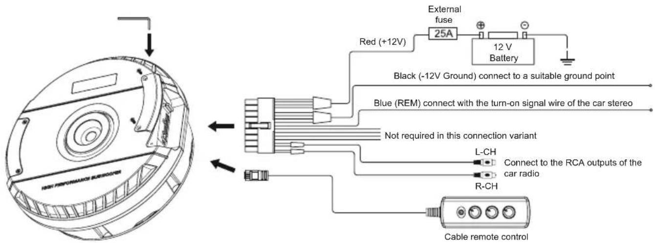
INTERCONNECTION BY RCA INPUTS WITH TURN-ON SIGNAL (REM):
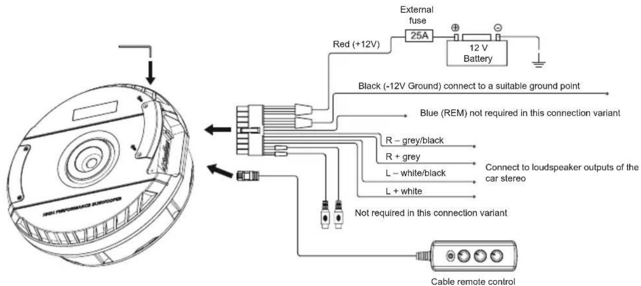
INTERCONNECTION BY HIGH LEVEL INPUTS WITH AUTO TURN-ON:
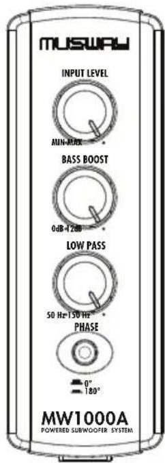
INPUT SENSITIVITY
Turn the INPUT LEVEL controller of the amplifier to the MIN position. Then turn the volume controller of the head unit to 80 - 90% of its full setting. Now turn INPUT LEVEL clockwise until you hear some distortion. Then turn back INPUT LEVEL slightly until you hear a cleaner sound.
VARIABLE BASS BOOST
By using the BASS BOOST controller you are able to increase the bass enhancement from 0 to 12 dB.
ATTENTION: Use the BASS BOOST wisely!
VARIABLE LOW PASS FILTER
Set the desired crossover frequency by using the controller LOW PASS. Thus to that only the frequencies below the chosen crossover frequency will be amplified and the subwoofer plays more precisely and efficient.
PHASE SWITCH
The PHASE switch allows to switch the phase from 0^ to 180^ to match the output signal with the vehicle's interior acoustic.
PROTECTION CIRCUIT
The PWR LED lights up green, if the amplifier is in operation.
The PRO LED lights up red, when the amplifier is overheated, or a short circuit occurs respective a too low impedance load is connected to the speaker outputs. If this events, the internal built-in protection circuit shuts down the amplifier automatically. The amplifier should work again properly after you have solved the problems.
Troubleshooting
-
Check all connections for defects or short circuits and correct them.
-
Provide sufficient cooling in the event of overheating and reduce the volume.
ABMESSAGENGEN / DIMENSIONS / DIMENSIONS / DIMENSIONI / DIMENSIONES
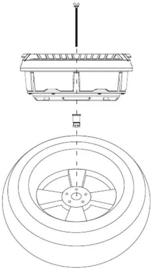
INSTALLATION / INSTALLATION / INSTALLATION / INSTALLAZIONE / INSTALACION
MUSWAY
MUSIC IS THE WAY
MUSWAY is a brand of Audio Design GmbH
Am Breilingsweg 3 - D-76709 Kronau
Tel. +49 7253 - 9465-0 · Fax +49 7253 - 946510
© Audio Design GmbH, All Rights Reserved
www.musway.de