Mover smart M - Auxiliary heating TRUMA - Free user manual and instructions
Find the device manual for free Mover smart M TRUMA in PDF.
Document temporarily unavailable
The manual is currently being transferred to our new server. It will be accessible again in a few hours. Thank you for your patience.
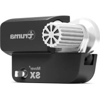
| Product type | Maneuvering system for single-axle caravan |
| Maximum permissible weight (caravan) | Up to 1800 kg |
| Maximum negotiable gradient | 13% (with 1800 kg) or 25% (with 1100 kg) |
| Maximum travel speed | 0.15 m/s |
| Operating voltage | 12 V DC |
| Maximum current consumption | 100 A |
| Average current consumption | 28 A |
| Current at rest (plug connected) | 60 mA |
| Current at rest (plug disconnected) | 30 mA |
| System weight (without battery) | 33 kg |
| Recommended battery type | Lead-acid, gel or AGM 12 V |
| Recommended battery capacity | 55 Ah, 70 Ah or 80 Ah |
| Recommended charger | Truma BC10 (PowerSet BC) |
| Remote control frequency | 868 MHz (Class 1) |
| Remote control battery | 9 V (MN 1604) |
| Remote control range | Up to 10 m from the center of the caravan |
| Motor type | 12 V DC motor (two drive units) |
| Main functions | Forward/backward movement, on-the-spot rotation, precise coupling |
| Maintenance | Regular check of roller-tyre distance (20 mm), cleaning with water jet and soft brush, check tyres and battery |
| Safety | Emergency stop via red button, automatic remote control shutdown after 3 min, battery cut-off switch |
| Spare parts and repairability | Original Truma parts only, repair by authorized specialist |
| Manufacturer's warranty | 24 months from initial sale |
| Document number | 10-digit reference + revision index |
Frequently Asked Questions - Mover smart M TRUMA
User questions about Mover smart M TRUMA
0 question about this device. Answer the ones you know or ask your own.
Ask a new question about this device
Download the instructions for your Auxiliary heating in PDF format for free! Find your manual Mover smart M - TRUMA and take your electronic device back in hand. On this page are published all the documents necessary for the use of your device. Mover smart M by TRUMA.