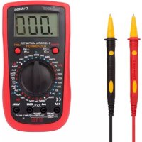
DVM895 - Multimeter VELLEMAN - Free user manual and instructions
Find the device manual for free DVM895 VELLEMAN in PDF.



| Product type | Digital multimeter |
| Brand | Velleman |
| Model | DVM895 |
| Display | LCD 3 1/2 digits, 62 x 36 mm, 1999 counts |
| Range selection | Manual |
| Measurement functions | DC/AC voltage, DC/AC current, resistance, capacitance, frequency, temperature, diode test, continuity |
| Maximum voltage | 600 V DC/AC (CAT III), 300 V (CAT IV) |
| Maximum current | 15 A (continuous 1 A) |
| Maximum resistance | 200 MΩ |
| Maximum capacitance | 200 μF |
| Maximum frequency | 20 kHz |
| Temperature | -50 °C to 800 °C (with type K probe) |
| Protection | Fuses: 0.5 A/600 V (5x20 mm) and 15 A/600 V (6x32 mm) |
| Power supply | 1 x 9 V 6F22 battery (included) |
| Dimensions | 190 x 100 x 40 mm |
| Weight | 300 g (with battery) |
| Overvoltage category | CAT III 600 V / CAT IV 300 V |
| Pollution degree | 2 |
| IP rating | IP20 |
| Operating temperature | 0 °C to 40 °C |
| Max. humidity | 80 % RH |
| Max. altitude | 2000 m |
| Included accessories | Test leads (CAT III 1000 V / CAT IV 600 V, 15 A, L=75 cm), battery |
| Maintenance | Clean with a damp cloth and mild detergent; replace battery/fuse by a professional |
| Warranty | 24 months (consumer) |
Frequently Asked Questions - DVM895 VELLEMAN
User questions about DVM895 VELLEMAN
0 question about this device. Answer the ones you know or ask your own.
Ask a new question about this device
Download the instructions for your Multimeter in PDF format for free! Find your manual DVM895 - VELLEMAN and take your electronic device back in hand. On this page are published all the documents necessary for the use of your device. DVM895 by VELLEMAN.
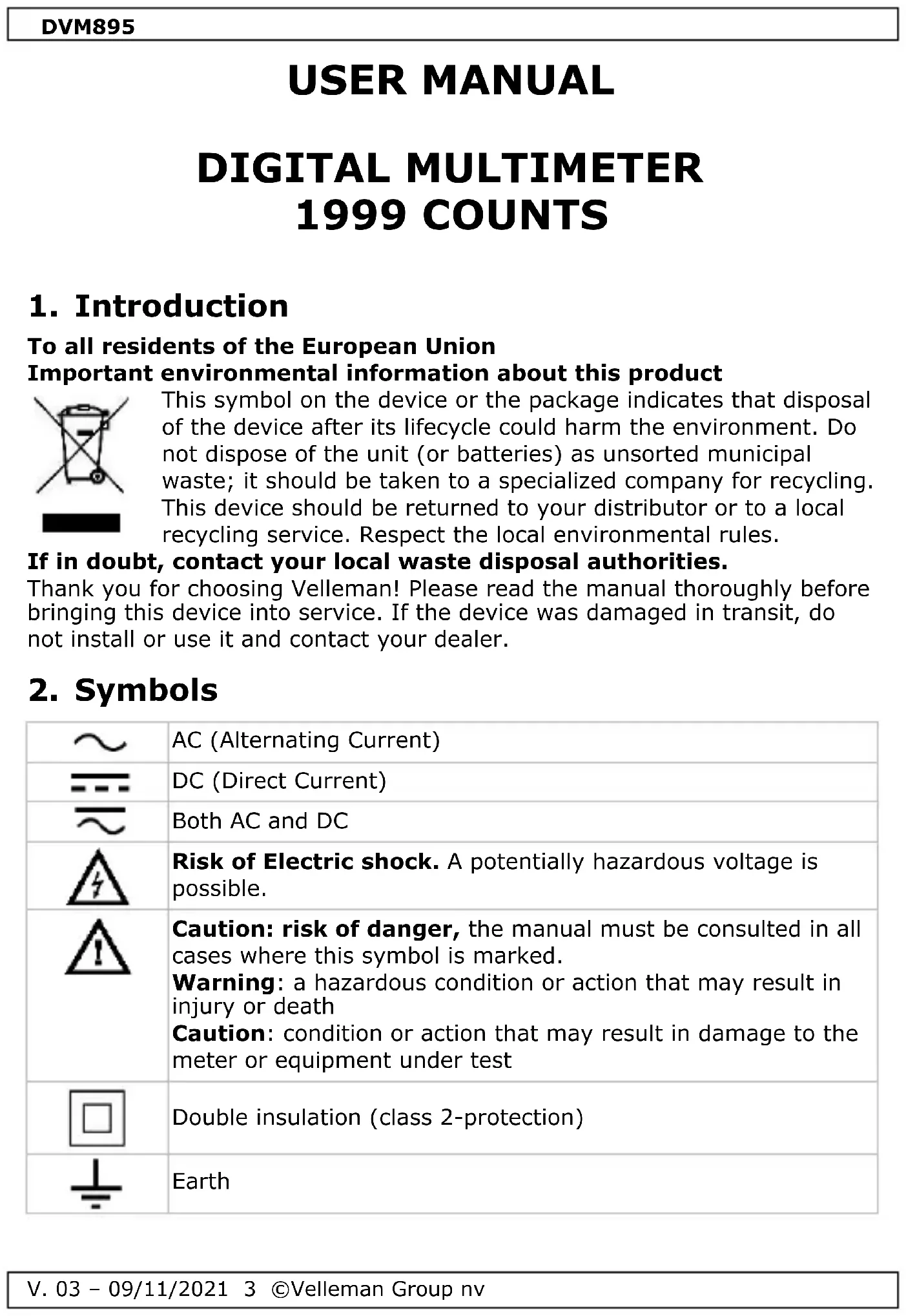
USER MANUAL DVM895 VELLEMAN
To all residents of the European Union
Important environmental information about this product

This symbol on the device or the package indicates that disposal of the device after its lifecycle could harm the environment. Do not dispose of the unit (or batteries) as unsorted municipal waste; it should be taken to a specialized company for recycling. This device should be returned to your distributor or to a local recycling service. Respect the local environmental rules.
If in doubt, contact your local waste disposal authorities.
Thank you for choosing Velleman! Please read the manual thoroughly before bringing this device into service. If the device was damaged in transit, do not install or use it and contact your dealer.
2. Symbols
 | AC (Alternating Current) |
 | DC (Direct Current) |
 | Both AC and DC |
 | Risk of Electric shock. A potentially hazardous voltage is possible. |
 | Caution: risk of danger, the manual must be consulted in all cases where this symbol is marked.Warning: a hazardous condition or action that may result in injury or deathCaution: condition or action that may result in damage to the meter or equipment under test |
 | Double insulation (class 2-protection) |
 | Earth |
DVM895
 | Fuse |
 | Capacitor |
 | Diode |
 | Continuity |
3. General Guidelines
Refer to the Velleman® Service and Quality Warranty on the last pages of this manual.
 | This symbol indicates: Read instructionsNot reading the instructions and manual can lead to damage, injury or death. |
 | This symbol indicates: DangerA hazardous condition or action that may result in injury or death. |
 | This symbol indicates: Risk of danger/damageRisk of a hazardous condition or action that may result in damage, injury or death. |
 | This symbol indicates: Attention; important informationIgnoring this information can lead to hazardous situations. |
 | WARNING: To avoid electrical shock always disconnect the test leads prior to opening the housing. To prevent fire hazards, only use fuses with the same ratings as specified in this manual.Remark: refer to the warning on the battery compartment. |
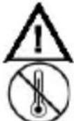 | Avoid cold, heat and large temperature fluctuations. When the unit is moved from a cold to a warm location, leave it switched off until it has reached room temperature. This to avoid condensation and measuring errors. |
 | Protect this device from shocks and abuse. Avoid brute force when operating. |
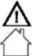 | Pollution degree 2-device. For indoor use only. Keep this device away from rain, moisture, splashing and dripping liquids. Not for industrial use.Refer to §8 Pollution degree. |
DVM895
 | Keep the device away from children and unauthorised users. |
 | Risk of electric shock during operation. Be very careful when measuring live circuits. |
 | There are no user-serviceable parts inside the device.Refer to an authorized dealer for service and/or spare parts. |
 | This is an installation category CAT IV measuring instrument. Refer to §7 Overvoltage/installation category. |
 | Read this addendum and the manual thoroughly. Familiarise yourself with the functions of the device before actually using it. |
 | All modifications of the device are forbidden for safety reasons. Damage caused by user modifications to the device is not covered by the warranty. |
 | Only use the device for its intended purpose. Using the device in an unauthorized way will void the warranty. Damage caused by disregard of certain guidelines in this manual is not covered by the warranty and the dealer will not accept responsibility for any ensuing defects or problems. |
 | WARNING – To avoid electric shock, fire or personal injury:Connect the common test lead before the live test lead and remove the live test lead before the common test lead.Disconnect the power and discharge all high-voltage capacitors before you measure resistance, continuity, capacitance or a diode junction.When using the temperature probe, do not connect the probe to live circuits. |
4. Maintenance
There are no user-serviceable parts inside the device. Refer to an authorized dealer for service and/or spare parts.
Before performing any maintenance activities, disconnect the test leads from the jacks.
For instructions on replacing battery or fuse, refer to §11 Battery and fuse replacement.
Do not apply abrasives or solvents to the meter. Use a damp cloth and mild detergent for cleaning purposes.
5. During Use

Risk of electric shock during operation. Be very careful when measuring live circuits.
- If the equipment is used in a manner not specified by the manufacturer, the protection provided by the equipment may be impaired.
- Never exceed the limit value for protection. This limit value is listed separately in the specifications for each range of measurement.
- Do not touch unused terminals when the meter is linked to a circuit which is being tested.
- Never use the meter with CAT III installations when measuring voltages that might exceed the safety margin of 600 V above earth ground. Never use the meter with CAT IV installations when measuring voltages that might exceed the safety margin of 300 V above earth ground.
- Set the range selector at its highest position if the intensity of the charge to be measured is unknown beforehand.
- Disconnect the test leads from the tested circuit before rotating the range selector in order to change functions.
- When carrying out measurements on a TV set or switching power circuits, always remember that the meter may be damaged by any high amplitude voltage pulses at test points.
- Always be careful when working with voltages above 60 VDC or 30 VAC rms. Keep your fingers behind the probe barriers at all times during measurement.
- Never perform resistance, diode or continuity measurements on live circuits. Make sure all capacitors in the circuit are depleted.
6. General Description
Refer to the illustration on page 2 of this manual:
- Display
3 12 digits, 7 segments, LCD: 62 x 36 mm - Power button
- Backlight button
- Function button
- "15A" jack
Insert the red test lead in this connector in order to measure a max. current of 15 A. - "mA" jack
Insert the red (positive) test lead in this connector to measure current (except 15 A). - "COM" jack
Insert the black (negative) test lead.
8. "VΩHz" jack
Insert the red (positive) test lead in this connector to measure voltage, resistance and frequency.
7. Overvoltage/Installation Category
DMMs are categorized depending on the risk and severity of transient overvoltage that might occur at the point of test. Transients are short-lived bursts of energy induced in a system, e.g. caused by lightning strike on a power line.
The existing categories according EN 61010-1 are:
| CAT II | A CAT II-rated meter is suitable for measurements in CAT I-environments and mono-phase appliances that are connected to the mains by means of a plug and circuits in a normal domestic environment, provided that the circuit is at least 10 m apart from a CAT III- or 20 m apart from a CAT IV-environment. E.g. household appliances, portable tools... |
| CAT III | A CAT III-rated meter is suitable for measurements in CAT I- and CAT II-environments, as well as for measurements on (fixed) mono-or poly-phased appliances which are at least 10 m apart from of a CAT IV-environment, and for measurements in or on distribution level equipment (fuse boxes, lighting circuits, electric ovens). |
| CAT IV | A CAT IV-rated meter is suitable for measuring in CAT I-, CAT II-and CAT III-environments as well as on the primary supply level. Note that for all measurements on equipment for which the supply cables run outdoors (either overhead or underground) a CAT IV meter must be used. |
Warning:
This device was designed in accordance with EN 61010-1 installation category CAT III 600 V and CAT IV 300 V. This implies that certain restrictions in use apply that are related to voltages and voltage peaks which can occur within the environment of use. Refer to the table above.

This device is only suitable for measurements up to 600 V in CAT III and up to 300 V in CAT IV
8. Pollution Degree
IEC 61010-1 specifies different types of pollution environments, for which different protective measures are necessary to ensure safety. Harsher environments require more protection, and the protection against the pollution which is to be found in a certain environment depends mainly on the insulation and the enclosure properties. The pollution degree rating of the DVM indicates in which environment the device may be used.
DVM895
| Pollution degree 1 | No pollution or only dry, nonconductive pollution occurs. The pollution has no influence. (only to be found in hermetically sealed enclosures) |
| Pollution degree 2 | Only nonconductive pollution occurs. Occasionally, temporary conductivity caused by condensation is to be expected.(home and office environments fall under this category) |
| Pollution degree 3 | Conductive pollution occurs, or dry nonconductive pollution occurs that becomes conductive due to condensation that is to be expected.(industrial environments and environments exposed to outside air - but not in contact with precipitation) |
| Pollution degree 4 | The pollution generates persistent conductivity caused by conductive dust or by rain or snow. (exposed outdoor environments and environments where high humidity levels or high concentrations of fine particles occur) |
Warning: This device was designed in accordance with EN 61010-1 pollution degree 2. This implies that certain restrictions in use apply that are related to pollution which can occur within the environment of use. Refer to the table above.

This device is only suitable for measurements in Pollution degree class 2 environments.
9. Specifications
This device is not calibrated when purchased!
Regulations concerning environment of use:
Use this meter only for measurements in CAT I, CAT II, CAT III and CAT IV environments (see §7).
Use this meter only in a pollution degree 2 environment (see §8).
Ideal working conditions include:
temperature: 0 °C to 40 °C (32 °F to 104 °F)
relative humidity: max. 80 % RH
altitude: max. 2000 m (6560 ft)
voltage 600 V
fuse protection
0.5 A/500 VAC/600 VDC, 5 x 20 mm (breaking capacity 1 kA)
15 A/1000 VAC/600 VDC, 6 x 32 mm (breaking capacity 10 kA)
power supply 1 x 9 V 6F22 (incl.)
display......LCD, 1999 counts
display dimensions 62 x 36 mm
ranging mode .... manual
over-range ....yes
DVM895
continuity buzzer......yes
diode test.....yes
low-battery indication .... yes
data hold .... no
backlight....yes
auto power-off ....yes
dimensions.... 190 x 100 x 40 mm
weight (with battery) 300 g
storage environment
temperature -20 °C to 60 °C
humidity .... < 90 % RH
test lead probe...... CAT III 1000 V/ CAT IV 600 V, 15 A; L = 75 cm
IP rating IP20
9.1 DC VOLTAGE

Do not measure circuits that may contain voltages
$$
6 0 0 \text { V D C } \text { or } > 6 0 0 \text { V A C } $$
| range | resolution | accuracy |
| 200 mV | 0.1 mV | ± (0.5 % rdg + 2 digits) |
| 2 V | 1 mV | |
| 20 V | 10 mV | |
| 200 V | 100 mV | |
| 600 V | 1 V | ± (0.8 % rdg + 2 digits) |
Overload protection: 600 V DC or AC rms
Impedance: 10 MΩ
9.2 AC VOLTAGE

Do not measure circuits that may contain voltages
$$
6 0 0 \text { V D C } \text { or } > 6 0 0 \text { V A C } $$
| range | resolution | accuracy |
| 2 V | 1 mV | ± (0.8 % rdg + 3 digits) |
| 20 V | 10 mV | |
| 200 V | 100 mV | |
| 600 V | 1 V | ± (1.2 % rdg + 3 digits) |
Average sensing, calibrated to rms of sine wave
Frequency range: 40-500 Hz
Overload protection: 600 V DC or AC rms
Impedance: 1 MΩ on 2 V range, 10 MΩ on other ranges
9.3 DC CURRENT
 | Do not measure circuits that may contain voltages > 600 VDC or > 600 VAC | |
| range | resolution | accuracy |
| 200 μA | 0.1 μA | ± (1.2 % rdg + 2 digits) |
| 2 mA | 1 μA | |
| 20 mA | 10 μA | |
| 200 mA | 100 μA | ± (1.5 % rdg + 2 digits) |
| 15 A | 10 mA | ± (2.0 % rdg + 3 digits) |
Overload protection: F0.5 A/600 V fuse, F15 A/600 V fuse
Continuous testing maximum steady-state current of 1 A
9.4 AC CURRENT
 | Do not measure circuits that may contain voltages > 600 VDC or > 600 VAC | |
| range | resolution | accuracy |
| 2 mA | 1 μA | ± (1.5 % rdg + 3 digits) |
| 20 mA | 10 μA | |
| 200 mA | 100 μA | ± (2.0 % rdg + 3 digits) |
| 15 A | 10 mA | ± (2.5 % rdg + 5 digits) |
Average sensing, calibrated to rms of sine wave
Frequency range: 40-500 Hz
Overload protection: F0.5 A/600 V fuse, F15 A/600 V fuse
Continuous testing maximum steady-state current of 1 A
9.5 RESISTANCE
 | Do not conduct resistance measurements on live circuits | |
| range | resolution | accuracy |
| 200 Ω | 0.1 Ω | ± (1.0 % rdg + 3 digits) |
| 2 kΩ | 1 Ω | ± (1.0 % rdg + 2 digits) |
| 20 kΩ | 10 Ω | |
| 200 kΩ | 100 Ω | |
| 2 MΩ | 1 kΩ | |
DVM895
| 20 MΩ | 10 kΩ | ± (1.5 % rdg + 3 digits) |
| 200 MΩ | 100 kΩ | ± (5.0 % rdg + 5 digits) |
Overload protection: 600 V DC or AC rms
9.6 CAPACITANCE
 | Do not conduct capacitance measurements on live circuits | |
| range | resolution | accuracy |
| 2000 pF | 1 pF | ± (2.5 % rdg + 10 digits) |
| 20 nF | 10 pF | ± (2.5 % rdg + 5 digits) |
| 200 nF | 100 pF | |
| 2 μF | 1 nF | |
| 20 μF | 10 nF | |
| 200 μF | 100 nF | ± (5.0 % rdg + 10 digits) |
Overload protection: F0.5 A/600 V fuse
9.7 DIODE AND CONTINUITY
 | Do not conduct diode or continuity measurements on live circuits | |
| range | description | test condition |
 | display reads the approximate forward voltage of the diode | forward DC current ± 1 mA reversed DC voltage ± 3 V |
 | built-in buzzer sounds if resistance < 50 Ω | open-circuit voltage ± 3 V |
Overload protection: 600 V DC or AC rms
9.8 FREQUENCY
 | Do not conduct frequency measurements on live circuits | |
| range | resolution | accuracy |
| 20 kHz | 10 Hz | ± (2.0 % rdg + 5 digits) |
Sensitivity: sine wave 0.5 V rms
Overload protection: 600 V DC or AC rms
9.9 TEMPERATURE
| range | accuracy | resolution | |
| °C | -50 to 150 °C | ± (3 °C + 1 digit) | 1 °C |
| 150 to 800 °C | ± (3 % + 1 digit) | ||
NiCr-NiSi sensor
Overload protection: F0.5 A/600 V fuse
10. Operation
10.1 DC VOLTAGE MEASUREMENT
 | Do not measure circuits that may contain voltages > 600 VDC or > 600 VAC |
 | Use extreme caution when measuring voltages higher than 60 VDC or 30 VAC rms.Always place your fingers behind the protective edges of the test probes while measuring! |
- Set the rotary switch in the desired "v---" position.
- Connect the red test lead to the "VΩHz" jack and the black lead to the "COM" jack.
- Connect the test leads to the source being measured.
- Read the voltage value and the polarity of the red test lead on the LCD display.
Notes
- If the range is not known beforehand, set the selector switch to a high range and lower gradually.
- An over-range is indicated by 1 or -1. Set to a higher range.
- The maximum input current is 600 V rms.
10.2 AC VOLTAGE MEASUREMENT
 | Do not measure circuits that may contain voltages > 600 VDC or > 600 VAC |
 | Use extreme caution when measuring voltages higher than 60 VDC or 30 VAC rms.Always place your fingers behind the protective edges of the test probes while measuring! |
- Set the rotary switch in the desired "v\~" position.
- Connect the red test lead to the "V Hz" jack and the black lead to the "COM" jack.
DVM895
- Connect the test leads to the source being measured.
- Read the voltage value and the polarity of the red test lead on the LCD display.
Notes
• See DC Voltage Measurement
10.3 DC CURRENT MEASUREMENT
 | Do not measure circuits that may contain voltages > 600 VDC or > 600 VAC |
 | Use extreme caution when measuring voltages higher than 60 VDC or 30 VAC rms.Always place your fingers behind the protective edges of the test probes while measuring! |
- Set the rotary switch in the desired "A---" position.
- Connect the red test lead to the "mA" jack and the black test lead to the "COM" jack (switch the red lead to the "15A" jack for measurements between 200 mA and 15 A).
- Open the circuit in which the current is to be measured and connect the test leads to the circuit IN SERIES.
- Read the current value and the polarity of the red lead connection on the LCD display.
Notes
- If the range is not known beforehand, set the selector switch to a high range and lower gradually.
- An over-range is indicated by 1 or -1. Set to a higher range.
- The maximum input current is 200 mA or 15 A depending upon the used jack. The maximum time of the 15 A range measurement each is 15 seconds.
10.4 AC CURRENT MEASUREMENT
 | Do not measure circuits that may contain voltages > 600 VDC or > 600 VAC |
 | Use extreme caution when measuring voltages higher than 60 VDC or 30 VAC rms.Always place your fingers behind the protective edges of the test probes while measuring! |
- Set the rotary switch in the desired "A\~" position.
DVM895
- Connect the red test lead to the "mA" jack and the black test lead to the "COM" jack (switch the red lead to the "15A" jack for measurements between 200 mA and 15 A).
- Open the circuit in which the current is to be measured and connect the test leads to the circuit IN SERIES.
- Read the current value and the polarity of the red lead connection on the LCD display.
Notes
• See DC Current Measurement
10.5 RESISTANCE MEASUREMENT

Do not conduct resistance measurements on live circuits. Make sure all capacitors in the circuit are depleted.
- Set the rotary switch in the desired "Ω" position.
- Connect the red test lead to the "VΩHz" jack and the black test lead to the "COM" jack.
- Connect the test leads to the resistor to be measured and read the LCD display.
Notes
- If the resistance being measured is connected to a circuit, turn off the power and discharge all capacitors before applying the test probes.
- An over-range is indicated by 1 or -1. Set to a higher range.
10.6 CAPACITANCE MEASUREMENT

Do not conduct capacitance measurements on live circuits. Make sure all capacitors in the circuit are depleted.
- Connect the red test lead to the "mA" jack and the black test lead to the "COM" jack.
- Set the rotary switch in the appropriate "Cx" range position.
- Connect the test leads to the source to be measured and read the LCD display.
Notes
- If the range is not known beforehand, set the selector switch to a high range and lower gradually.
- Turn off the power and discharge all capacitors before applying the test probes.
10.7 DIODE AND CONTINUITY TEST

Do not conduct diode or continuity measurements on live circuits. Make sure all capacitors in the circuit are depleted.
- Set the rotary switch in the “▶” (diode) or “•”) (continuity) position.
- Connect the red test lead to "VΩHz" jack and the black one to the "COM" jack.
- For measuring the diode, connect the red test lead to the anode of the diode to be tested and the black test lead to the cathode of the diode. The approx. forward voltage drop of the diode will be displayed. For measuring continuity, connect the test leads to two points of the circuit to be tested. If continuity exists, the built-in buzzer will sound.
10.8 FREQUENCY MEASUREMENT

Do not frequency measurements on live circuits. Make sure all capacitors in the circuit are depleted.
- Set the rotary switch in the "20kHz" position.
- Connect the red test lead to "VΩHz" jack and the black one to the "COM" jack.
- Connect the test leads to the source to be measured and read the LCD display.
10.9 TEMPERATURE MEASUREMENT
- Connect the red banana plug to "mA" jack and the black one to "COM".
- Set the rotary switch in the "°C" position.
- Put the probe into the field to be measured and read the LCD display.
10.10 BACKLIGHT
Press "LIGHT" to switch the backlight on or off.
11. Battery and Fuse Replacement
WARNING: To avoid electrical shock always disconnect the test leads prior to opening the housing. To prevent fire hazards, only use fuses with the same ratings as specified in this manual. Remark: refer to the warning on the battery compartment

There are no user-serviceable parts inside the device. Refer to an authorized dealer for service and/or spare parts.
DVM895

Equipment must be isolated or disconnected from the HAZARDOUS LIVE voltage before access (referring to battery replacement by operator).
- When" " is displayed, the battery should be replaced.
- Fuses rarely need replacement and blown fuses almost always result from human error.
To replace the battery:
- Switch off the meter.
- Remove the screw at the back of the case and gently open the housing.
- Remove the old battery and insert a new one.
- Close the housing and fasten the screw.
Battery: 1 x 9 V 6F22, make sure to respect the polarity
Fuses: 0.5 A/500 VAC/600 VDC, 5 x 20 mm, 15 A/1000 VAC/600 V, 6 x 32 mm
Make sure the meter is closed tight and put the protective edge back in place before using the meter.
12. Troubleshooting
If the device acts abnormal while measuring, this means that the internal fuse is defective.
Keep in mind that a low battery level could lead to incorrect measurements. Replace the battery on a regular basis.
(Tip: the reduced luminosity of the backlight/LCD display indicates a low battery level.)
Use this device with original accessories only. Velleman Group nv cannot be held responsible in the event of damage or injury resulting from (incorrect) use of this device. For more info concerning this product and the latest version of this manual, please visit our website www.velleman.eu. The information in this manual is subject to change without prior notice.
© COPYRIGHT NOTICE
The copyright to this manual is owned by Velleman Group nv. All worldwide rights reserved. No part of this manual may be copied, reproduced, translated or reduced to any electronic medium or otherwise without the prior written consent of the copyright holder.
HANDLEIDING
DIGITALE MULTIMETER 1999 COUNTS
1. Inleiding
10.2 MESURER LA TENSION CA

testowanie diod......tak
Velleman® Service and Quality Warranty
Since its foundation in 1972, Velleman® acquired extensive experience in the electronics world and currently distributes its products in over 85 countries.
All our products fulfil strict quality requirements and legal stipulations in the EU. In order to ensure the quality, our products regularly go through an extra quality check, both by an internal quality department and by specialized external organisations. If, all precautionary measures notwithstanding, problems should occur, please make appeal to our warranty (see guarantee conditions).
General Warranty Conditions Concerning Consumer Products (for EU):
- All consumer products are subject to a 24-month warranty on production flaws and defective material as from the original date of purchase.
- Velleman® can decide to replace an article with an equivalent article, or to refund the retail value totally or partially when the complaint is valid and a free repair or replacement of the article is impossible, or if the expenses are out of proportion.
You will be delivered a replacing article or a refund at the value of 100% of the purchase price in case of a flaw occurred in the first year after the date of purchase and delivery, or a replacing article at 50% of the purchase price or a refund at the value of 50% of the retail value in case of a flaw occurred in the second year after the date of purchase and delivery.
• Not covered by warranty:
- all direct or indirect damage caused after delivery to the article (e.g. by oxidation, shocks, falls, dust, dirt, humidity...), and by the article, as well as its contents (e.g. data loss), compensation for loss of profits;
- consumable goods, parts or accessories that are subject to an aging process during normal use, such as batteries (rechargeable, non-rechargeable, built-in or replaceable), lamps, rubber parts, drive belts... (unlimited list);
- flaws resulting from fire, water damage, lightning, accident, natural disaster, etc....;
- flaws caused deliberately, negligently or resulting from improper handling, negligent maintenance, abusive use or use contrary to the manufacturer's instructions;
- damage caused by a commercial, professional or collective use of the article (the warranty validity will be reduced to six (6) months when the article is used professionally);
- damage resulting from an inappropriate packing and shipping of the article;
- all damage caused by modification, repair or alteration performed by a third party without written permission by Velleman®.
- Articles to be repaired must be delivered to your Velleman® dealer, solidly packed (preferably in the original packaging), and be completed with the original receipt of purchase and a clear flaw description.
- Hint: In order to save on cost and time, please reread the manual and check if the flaw is caused by obvious causes prior to presenting the article for repair. Note that returning a non-defective article can also involve handling costs.
- Repairs occurring after warranty expiration are subject to shipping costs.
- The above conditions are without prejudice to all commercial warranties.
The above enumeration is subject to modification according to the article (see article's manual).
NL


- To all residents of the European Union
- Important environmental information about this product
- If in doubt, contact your local waste disposal authorities.
- Symbols
- DVM895
- General Guidelines
- Maintenance
- During Use
- General Description
- "VΩHz" jack
- Overvoltage/Installation Category
- Warning:
- Pollution Degree
- Specifications
- DC VOLTAGE
- AC VOLTAGE
- DC CURRENT
- AC CURRENT
- RESISTANCE
- TEMPERATURE
- Operation
- DC VOLTAGE MEASUREMENT
- Notes
- AC VOLTAGE MEASUREMENT
- DC CURRENT MEASUREMENT
- AC CURRENT MEASUREMENT
- RESISTANCE MEASUREMENT
- CAPACITANCE MEASUREMENT
- DIODE AND CONTINUITY TEST
- FREQUENCY MEASUREMENT
- TEMPERATURE MEASUREMENT
- BACKLIGHT
- Battery and Fuse Replacement
- To replace the battery:
- Troubleshooting
- © COPYRIGHT NOTICE
- HANDLEIDING
- DIGITALE MULTIMETER 1999 COUNTS
- Inleiding
- MESURER LA TENSION CA
- Velleman® Service and Quality Warranty
- General Warranty Conditions Concerning Consumer Products (for EU):
- • Not covered by warranty:
- The above enumeration is subject to modification according to the article (see article's manual).
- NL
Brand : VELLEMAN
Model : DVM895
Category : Multimeter