PowerSpace P2600A - Audio Receiver BOSE - Free user manual and instructions
Find the device manual for free PowerSpace P2600A BOSE in PDF.
User questions about PowerSpace P2600A BOSE
0 question about this device. Answer the ones you know or ask your own.
Ask a new question about this device
Download the instructions for your Audio Receiver in PDF format for free! Find your manual PowerSpace P2600A - BOSE and take your electronic device back in hand. On this page are published all the documents necessary for the use of your device. PowerSpace P2600A by BOSE.
USER MANUAL PowerSpace P2600A BOSE
natural_image
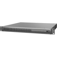
Exterior view of a power storage rack unit (no visible text or labels on the equipment body)PowerSpace
Versatile Power Amplifiers
P2600A / P21000A / P4300A
Installation Guide....2
Please read and keep all safety and use instructions.
This product is intended for installation by professional installers only! This document is intended to provide professional installers with basic installation and safety guidelines for this product in typical fixed-installation systems. Please read this document and all safety warnings before attempting installation.
-
Read these instructions.
-
Keep these instructions.
-
Heed all warnings.
-
Follow all instructions.
-
Do not use this apparatus near water.
-
Clean only with a dry cloth.
-
Do not block any ventilation openings. Install in accordance with the manufacturer's instructions.
-
Do not install near any heat sources such as radiators, heat registers, stoves, or other apparatus (including amplifiers) that produce heat.
-
Do not defeat the safety purpose of the polarized or grounding-type plug. A polarized plug has two blades with one wider than the other. A grounding type plug has two blades and a third grounding prong. The wide blade or the third prong are provided for your safety. If the provided plug does not fit into your outlet, consult an electrician for replacement of the obsolete outlet.
-
Protect the power cord from being walked on or pinched particularly at plugs, convenience receptacles, and the point where they exit from the apparatus.
-
Only use attachments/accessories specified by the manufacturer.
-
Use only with the cart, stand, tripod, bracket, or table specified by the manufacturer, or sold with the apparatus. When a cart is used, use caution when moving the cart/apparatus combination to avoid injury from tip-over.
-
Unplug this apparatus during lightning storms or when unused for long periods of time.
-
Refer all servicing to qualified personnel. Servicing is required when the apparatus has been damaged in any way, such as power-supply cord or plug is damaged, liquid has been spilled or objects have fallen into the apparatus, the apparatus has been exposed to rain or moisture, does not operate normally, or has been dropped.
Safety Symbols
These symbols on the product mean the following:

This symbol on the product means there are important operating and maintenance instructions in this guide.

This symbol on the product means there is uninsulated, dangerous voltage within the product enclosure that may present a risk of electrical shock.

To reduce the risk of electric shock, do not remove cover (or back). No user-serviceable parts inside. Refer servicing to qualified personnel.

WARNINGS/CAUTIONS


Contains small parts which may be a choking hazard. Not suitable for children under age 3.

Use at altitude less than 2000 meters only.
- All Bose products must be installed in accordance with local, state, federal and industry regulations. It is the installer's responsibility to ensure installation of the loudspeakers and mounting system is performed in accordance with all applicable codes, including local building codes and regulations. Consult the local authority having jurisdiction before installing this product.
• Do not mount the product in locations where condensation may occur. - This product is not intended for installation or use in indoor water facility areas (including, without limitation, indoor pools, indoor water parks, hot tub rooms, saunas, steam rooms and indoor skating rinks).
- Do not expose this product to dripping or splashing, and do not place objects filled with liquids, such as vases, on or near the product.
• To reduce the risk of fire or electrical shock, do not expose this product to rain, liquids or moisture. - Keep the product away from fire and heat sources. Do not place naked flame sources, such as lighted candles, on or near the product.
- Do not place or install the bracket or product near any heat sources, such as fireplaces, radiators, heat registers or other apparatus (including amplifiers) that produce heat.
- Due to ventilation requirements, do not place the product in a confined space such as in a wall cavity or in an enclosed cabinet.
• Do not make unauthorized alterations to this product.
• Do not use a power inverter with this product.
• Do not use in vehicles or boats. - Provide an earth connection or ensure the socket outlet incorporates a protective earthing connection before connecting the plug to the mains socket outlet.
- Dansk: Apparatets stikprop skal tilsluttes en stikkontakt med jord, som giver forbindelse til stikproppens jord.
- Suomi: Laite on liitettävä suojamaadoituskoskettimilla varustettuun pistorasiaan.
• Norsk Apparatet må tilkoples jordet stikkontakt. - Svenska: Apparaten skall anslutas till jordat uttag.
- Where the mains plug or an appliance coupler is used as the disconnect device, the disconnect device shall remain readily operable.
• Only use the mounting hardware recommended by the rack manufacturer. - Avoid touching uninsulated wiring or wiring terminals. This product's audio wiring terminals carry voltage that can result in discomfort upon contact.
Regulatory Information
CAN ICES-3 (A)/NMB-3(A)
This device complies with part 15 of the FCC Rules and with Industry Canada license-exempt RSS standard(s). Operation is subject to the following two conditions: (1) This device may not cause harmful interference, and (2) this device must accept any interference received, including interference that may cause undesired operation.
NOTE: This equipment has been tested and found to comply with the limits for a Class A digital device, pursuant to part 15 of the FCC Rules. These limits are designed to provide reasonable protection against harmful interference when the equipment is operated in a commercial environment. This equipment generates, uses, and can radiate radio frequency energy and, if not installed and used in accordance with the instruction manual, may cause harmful interference to radio communications. Operation of this equipment in a residential area is likely to cause harmful interference in which case the user will be required to correct the interference at their own expense.
Changes or modifications not expressly approved by Bose Corporation could void the user's authority to operate this equipment.
WARNING: This is a class A product. In a domestic environment this product may cause radio interference in which case the user may be required to take adequate measures.
Shielded cables are required to maintain regulatory compliance.
This product meets all EN55103-2 immunity requirements for E2 electromagnetic environment.
Initial turn on inrush current:
P21000A: 13.7 A (230 VAC 50 Hz), 7.6 A (120 VAC 50 Hz)
P4300A/P2600A: 14.4 A (230 VAC 50 Hz), 7.6 A (120 VAC 50 Hz)
Inrush current after AC mains interruption of 5 seconds:
PZ1000A: 8.2 A (230 VAC 50 Hz), 5.4 A (120 VAC 50 Hz)
P4300A/P2600A: 9.6 A (230 VAC 50 Hz), 6.1 A (120 VAC 50 Hz)
CE This product conforms to all applicable EU directive requirements. The complete declaration of conformity can be found at: www.Bose.com/compliance

This product conforms to all applicable Electromagnetic Compatibility Regulations 2016 and all other applicable UK regulations. The complete declaration of conformity can be found at: www.Bose.com/compliance

This symbol means the product must not be discarded as household waste, and should be delivered to an appropriate collection facility for recycling. Proper disposal and recycling helps protect natural resources, human health and the environment. For more information on disposal and recycling of this product, contact your local municipality, disposal service, or the shop where you bought this product.
China Restriction of Hazardous Substances Table
| Names and Contents of Toxic or Hazardous Substances or Elements | ||||||
| Toxic or Hazardous Substances and Elements | ||||||
| Part Name | Lead(Pb) | Mercury(Hg) | Cadmium(Cd) | Hexavalent(CR(VI)) | PolybrominatedBiphenyl(PBB) | Polybrominateddiphenylether(PBDE) |
| PCBs X 0 0 0 | O | O | ||||
| Metal Parts | X 0 0 | O | O | O | ||
| Plastic Parts | O 0 0 | O | O | O | ||
| Speakers | X 0 0 | O | O | O | ||
| Cables X 0 0 0 | O | O | ||||
| This table is prepared in accordance with the provisions of SJ/T 11364.O: Indicates that this toxic or hazardous substance contained in all of the homogeneous materials for this part is below the limit requirement of GB/T 26572. | ||||||
| X: Indicates that this toxic or hazardous substance contained in at least one of the homogeneous materials used for this part is above the limit requirement of GB/T 26572. | ||||||
Taiwan Restriction of Hazardous Substances Table
| Equipment name: PowerSpace Amplifiers P2600A, P21000A, and P4500A, Type designation: 803286, 803287, 803288 | ||||||
| Restricted substances and its chemical symbols | ||||||
| Unit | Lead (Pb) | Mercury (Hg) | Cadmium (Cd) | Hexavalent chromium (Cr+b) | Polybrominated biphenyls (PSB) | Polybrominated diphenyl others (PBDE) |
| PCBs | - | ○ | ○ | ○ | ○ | ○ |
| Metal Parts | - | ○ | ○ | ○ | ○ | ○ |
| Plastic Parts | ○ | ○ | ○ | ○ | ○ | ○ |
| Speakers | - | ○ | ○ | ○ | ○ | ○ |
| Cables | - | ○ | ○ | ○ | ○ | ○ |
| Note 1: “o” indicates that the percentage content of the restricted substance does not exceed the percentage of reference value of presence. Note 2: The “-” indicates that the restricted substance corresponds to the exemption. | ||||||
Date of Manufacture: The eighth digit in the serial number indicates the year of manufacture; "7" is 2007 or 2017.
China Importer: Bose Electronics (Shanghai) Company Limited, Level 6, Tower D. No. 2337 Gudai Rd. Minhang District, Shanghai 201100
UK Importer: Bose Limited Bose House, Quayside Chatham Maritime, Chatham, Kent, ME4 4Q7, United Kingdom
EU Importer: Bose Products B.V., Gorslaan 60, 1441 RG Purmerend, The Netherlands
Mexico Importer: Bose de México, S. de R.L. de C.V., Paseo de las Palmas 405-204, Lomas de Chapultepec, 11000 México, D.F. For importer & service information: +5255 (5202) 3545
Taiwan Importer: Bose Taiwan Branch, 9F-A1, No. 10, Section 3, Minsheng East Road, Taipei City 104, Taiwan.
Phone Number: +886-2-2514 7676
Bose and PowerSpace are trademarks of Bose Corporation.
Bose Corporation Headquarters: 1-877-230-5639
©2022 Bose Corporation. No part of this work may be reproduced, modified, distributed or otherwise used without prior written permission.
Warranty Information
This product is covered by a limited warranty.
For warranty details, visit PRO.BOSE.COM.
Package Contents
Accessories P2600A P21000A P4300A
natural_image
3D illustration of a black cable with two connectors (no text or symbols)AC power cord 111

Cat 5e cable (1 m / 3 ft)
111

2-pin Euroblock connector (black) 111
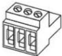
3-pin Euroblock connector (green) 2 2 4

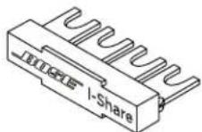
I-Share jumper 112

Terminal fork (14-16 gauge)
55
10
Technical Information
For additional technical information including specifications, block diagrams, and AC current draw statistics, please visit the PowerSpace product page on PRO.BOSE.COM.
| Power Rating | P2600A | P21000A | P4300A |
| Amplifier Power | 2 × 600 W(THD+N<0.04%,1kHz,4-8Ω,70/100V) | 2 × 1000 W(THD+N<0.04%,1kHz,4-8Ω,70/100V) | 4 × 300 W(THD+N<0.04%,1kHz,4-8Ω,70/100V) |
| I-Share Mode Power | 1 × 1200 W (2-4Ω, 70/100V) | 1 × 2000 W (2-4Ω, 70/100V) | 2 × 600 W (2-4Ω, 70/100V)(Each channel pair can be I-Shared) |
| Gain (Low-Z mode) | 35 dB | 37 dB | 32 dB |
| Gain (70V mode) | 35 dB | 35 dB | 35 dB |
| Gain (100V mode) | 38 dB | 38 dB | 38 dB |
| Physical | |||
| Operational temperature range | 100 V to 264 VAC: +40 °C to 0 °C | ||
| Storage temperature range | +70 °C to -40 °C | ||
| Dimensions(H × W × D) | 44 mm × 483 mm × 414 mm (1.7 in × 19.0 in × 16.3 in) | ||
| Net Weight | 6.2 kg (13.7 lb) | 6.6 kg (14.6 lb) | 6.6 kg (14.6 lb) |
| Shipping Weight | 8.2 kg (18.1 lb) | 8.6 kg (19.0 lb) | 8.6 kg (19.0 lb) |
PowerSpace P2600A/P21000A
Front Panel
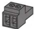
text_image
BOSE POWER SIGNAL 1 P4 2 PowerSpace Variable Power Antenna P2600A| 1 Power switch: | In/Out standby mode. | |
| 2 Power LED: | Power or fault state indication. | White (solid): Power is onWhite (blinking): Unit is in standby modeRed (solid): Power supply faultRed (blinking): Thermal fault |
| 3 Input Signal LED: | Each LED operates independently. | Green: Signal presentAmber: Input is near clippingRed: Input is clipping |
| 4 Output Limit LED: | Each LED operates independently. | Amber: Amplifier limiting an outputRed (both solid): Amplifier faultRed (blinking): Outputs are muted |
Faults Only
| Power Supply Fault* | Thermal Fault | Amplifier Fault | |
| Power LED | Solid red | Blinking red | — |
| Limit LEDs | — | All solid red | All solid red |
*Except for AC loss
If a power supply or amplifier fault cannot be cleared, then the amplifier needs to be replaced.
Rear Panel

text_image
OUTPUT ATTENUATION MUTE 1 2 OUTPUT Switch Settings OUT OK RIP/ANNUAL/ANNUAL/ANNUAL/ANNUAL/ANNUAL/ANNUAL/ANNUAL/ANNUAL/ANNUAL/ANNUAL/ANNUAL/ANNUAL/ANNUAL/ANNUAL/ANNUAL/ANNUAL/ANNUAL/ANNUAL/ANNUAL/ANNUAL/ANNUAL/ANNUAL/ANNUAL/ANNUAL/ANNUAL/ANNUA 1 2 3 4 5 6 7 8 9 10 Status 1 + 2 - INPUT Amplink TNC INPUT USB LINK ERP LINK 1 + 2 + UPDATE BASE (CONSENSIT) LED (C:50Hz) LOW (C:50Hz) BOSKY - HUNZ 2 STOW MAX① Output Attenuation controls: Output attenuation controls for each output. Turn the controls clockwise to decrease attenuation and counter-clockwise to increase attenuation. The attenuator must be at 0 dB attenuation for the respective output to reach rated power.
② Mute: Normally open or normally closed dry contacts can mute all outputs. Mute polarity can be inverted by a DIP switch.
3 Output terminal block: 4-terminal block connector for loudspeaker connections. Each channel can deliver up to 600 watts (P2600A) or up to 1000 watts (P21000A) regardless of load into 4Ω, 8Ω, 70V, or 100V. Outputs can be I-Shared.
④ DIP switches: A bank of switches used to set amplifier configuration.
- Auto Standby: If enabled (On), the amplifier goes into lower-power mode after 20 minutes without an input signal. If in lower-power mode and an audio signal is detected, the amplifier will automatically wake and amplify audio within one second. The default position is Off.
- Mute Polarity: Switch mute polarity between NO (normally open) or NC (normally closed). NO is the default position.
- Global Out: Sets the output capability to 70V or 100V for all outputs that have their DIP switch set to Hi-Z. In 70V Hi-Z mode and Low-Z mode, 100 V p and 70 V RMS limiters are automatically loaded. In 100V Hi-Z mode, 100 V _RMS limiters are automatically loaded.
- Output 1: Select 70/100V high-impedance output (Hi-Z) or 4-8Ω low-impedance output (Low-Z) for Output 1.
- Output 2: Select 70/100V high-impedance output (Hi-Z) or 4-8Ω low-impedance output (Low-Z) for Output 2.
- I-Share 1 & 2: Deliver 2× channel power by combining the current of Outputs 1 & 2. While the amplifier is off or in Standby mode, set this DIP switch to On and install the included jumper across the four-output terminals. Then wire the loudspeaker load to the amplifier using terminals 1+ and 1- (or 2+ and 2-).
⑤ Input Select control: Dial selects if analog or AmpLink audio inputs are used. The default state is analog 1:1.
6 AmpLink ports: Input RJ-45 connector that receives up to eight digital channels from a Bose AmpLink product. The amp also supports a Thru path for daisy-chaining all eight digital audio channels to up to eight other Bose AmpLink products, at a maximum distance of 10 meters between products.

CAUTION: Shielded EIA/TIA 568B straight Cat 5 cable, or equivalent, is required for proper AmpLink operation. Unshielded cable is not supported and may cause AmpLink audio to operate improperly. Do NOT connect either RJ-45 port to an Ethernet-based network.
⑦ Analog Input: Line-level input for balanced analog audio signals.
8 Update port: Used for firmware updates.
⑨ Gain/Sensitivity switch: Slide switch to set global gain/sensitivity setting to high gain (-10 dBv sensitivity), mid gain (4 dBu sensitivity), or low gain (14 dBu sensitivity).
10 Power input: Power cord connection (IEC 60320-C14 inlet). Removing the power cord when the amplifier is on is an acceptable power-down method.
PowerSpace P4300A
Front Panel

text_image
1 2 3 4 BOSE POWER SIGNAL 1 2 : 2 PowerSpace P4300A| 1 Power switch: | In/Out standby mode. | |
| 2 Power LED: | Power or fault state indication. | White (solid): Power is onWhite (blinking): Unit is in standby modeRed (solid): Power supply faultRed (blinking): Thermal fault |
| 3 Input Signal LED: | Each LED operates independently. | Green: Signal presentAmber: Input is near clippingRed: Input is clipping |
| 4 Output Limit LED: | Each LED operates independently. | Amber: Amplifier limiting an outputRed (solid): Ch 1 & Ch 2 amplifier A faultCh 3 & Ch 4 amplifier B faultRed (all solid): Thermal faultRed (blinking): Outputs are muted |
Faults Only
| Power Supply Fault* | Thermal Fault | Amplifier Fault | |
| Power LED | Solid red | Blinking red | — |
| Limit LEDs | — | All solid red | Ch 1 & 2 solid red, Amplifier A Ch 3 & 4 solid red, Amplifier B |
*Except for AC loss
If a power supply or amplifier fault cannot be cleared, then the amplifier needs to be replaced.
Rear Panel

text_image
OUTPUT ATTENUATION MUTE OUTPUT INPUT Analog Input 0.17 11/24LL Amplitude Input 1 S=13 - 1 INPUT 2 GAR (ON/OFF/INT) HIGH RED LOW 200 MHz 150 MHz ADD COMPRESSOR COMPRESSOR COMPRESSOR COMPRESSOR COMPRESSOR COMPRESSOR COMPRESSOR COMPRESSOR COMPRESSOR COMPRESSOR COMPRESSOR COMPRESSOR COMPRESSOR COMPRESSOR COMPRESSOR COMPRESSOR COMPRESSOR COMPRESSOR COMPRESSOR COMPRESSOR COMPRESSOR COMPRESSOR COMPRESSOR COMPRESSOR COMPRESSOR COMPRESSORD COMPRESSORD COMPRESSORD COMPRESSORD COMPRESSORD COMPRESSORD COMPRESSORD COMPRESSORD COMPRESSORD COMPRESSORD COMPRESSORD COMPRESSORD COMPRESSORD COMPRESSORD COMPRESSORD COMPRESSORD COMPRESSORD COMPRESSORD COMPRESSORD COMPRESSORD COMPRESSORD COMPRESSORD COMPRESSORD COMPRESSORD COMPRESSORD COMPRESSORM COMPRESSORM COMPRESSORM COMPRESSORM COMPRESSORM COMPRESSORM COMPRESSORM COMPRESSORM COMPRESSORM COMPRESSORM COMPRESSORM COMPRESSORM COMPRESSORM COMPRESSORM COMPRESSORM COMPRESSORM COMPRESSORM COMPRESSORM COMPRESSORM COMPRESSORM COMPRESSORM COMPRESSORM COMPRESSORM COMPRESSORM COMPRESSORM COMPRESSFORM COMPRESSFORM COMPRESSFORM COMPRESSFORM COMPRESSFORM COMPRESSFORM COMPRESSFORM COMPRESSFORM COMPRESSFORM COMPRESSFORM COMPRESSFORM COMPRESSFORM COMPRESSFORM COMPRESSFORM COMPRESSFORM COMPRESSFORM COMPRESSFORM COMPRESSFORM COMPRESSFORM COMPRESSFORM COMPRESSFORM COMPRESSFORM COMPRESSFORM COMPRESSFORM COMPRESSFORM COMPRESSORM COMPRESSORM COMPRESSORM COMPRESSORM COMPRESSORM COMPRESSORM COMPRESSORM COMPRESSORM COMPRESSORM COMPRESSORM COMPRESSORM① Output Attenuation controls: Output attenuation controls for each output. Turn the controls clockwise to decrease attenuation and counterclockwise to increase attenuation. The attenuator must be at 0 dB attenuation for the respective output to reach rated power.
② Mute: Normally open or normally closed dry contacts can mute all outputs. Mute polarity can be inverted by a DIP switch.
③ Output terminal block: 8-terminal block connector for loudspeaker connections. Each channel can deliver up to 300 watts regardless of load into 4Ω, 8Ω, 70V, or 100V. Each output pair can be I-Shared.
④ DIP switches: A bank of switches used to set amplifier configuration.
- Auto Standby: If enabled (On), the amplifier goes into lower-power mode after 20 minutes without an input signal. If in lower-power mode and an audio signal is detected, the amplifier will automatically wake and amplify audio within one second. The default position is Off.
- Mute Polarity: Switch mute polarity between NO (normally open) and NC (normally closed). NO is the default position.
- Global Out: Sets the output capability to 70V or 100V for all outputs that have their DIP switch set to HI-Z. In 70V Hi-Z mode and Low-Z mode, 100 V p and 70 V RMS limiters are automatically loaded. In 100V Hi-Z mode, 100 V _RMS limiters are automatically loaded.
- Output 1: Select 70/100V high-impedance output (HI-Z) or 4-8Ω low-impedance output (Low-Z) for Output 1.
- Output 2: Select 70/100V high-impedance output (Hi-Z) or 4-8Ω low-impedance output (Low-Z) for Output 2.
- Output 3: Select 70/100V high-impedance output (HI-Z) or 4-8Ω low-impedance output (Low-Z) for Output 3.
- Output 4: Select 70/100V high-impedance output (HI-Z) or 4-8Ω low-impedance output (Low-Z) for Output 4.
- I-Share 1 & 2: Deliver 2× channel power by combining the current of Outputs 1 & 2.
- I-Share 3 & 4: Deliver 2× channel power by combining the current of Outputs 3 & 4.
Note: While the amplifier is off or in Standby mode, set one or both I-Share DIP switches to On and install the included jumper(s) across the first four and/or last four terminals. Then wire the loudspeaker load(s) to the amplifier. Wire the I-Share 1 & 2 loudspeaker load to the amplifier using 1+ and 1- (or 2+ and 2-). Wire the I-Share 3 & 4 loudspeaker load to the amplifier using terminals 3+ and 3- (or 4+ and 4-).
⑤ Input Select control: Dial selects if analog or AmpLink audio inputs are used. The default state is analog 1:1.
⑥ AmpLink ports: Input RJ-45 connector that receives up to eight digital channels from a Bose AmpLink product. The amp also supports a Thru path for daisy-chaining all eight digital audio channels to up to eight other Bose AmpLink products, at a maximum distance of 10 meters between products.
CAUTION: Shielded EIA/TIA 568B straight Cat 5 cable, or equivalent, is required for proper AmpLink operation. Unshielded cable is not supported and may cause AmpLink audio to operate improperly. Do not connect either RJ-45 port to an Ethernet-based network.
7 Analog Input: Line-level input for balanced analog audio signals.
8 Update port: Used for firmware updates.
⑨ Gain/Sensitivity switch: Slide switch to set global gain/sensitivity setting to high gain (-10 dBv sensitivity), mid gain (4 dBu sensitivity), or low gain (14 dBu sensitivity).
10 Power Input: Power cord connection (IEC 60320-C14 inlet). Removing the power cord when the amplifier is on is an acceptable power-down method.
Setting Up a PowerSpace Amplifier
- Starting with the amplifier power Off, set the rear-panel switches as needed for the application. Then make all required power and audio connections.
- Press the Power switch on the front panel to power the amplifier On.
- Depending on the loudspeakers you are configuring with your PowerSpace amplifier, do one of the following:
A. If all outputs are set to drive 70/100V high-impedance loudspeakers, rotate each corresponding Output Attenuation control to 0 dB attenuation. Set each loudspeaker tap to the appropriate setting. Based on the total loudspeaker tap settings, the amplifier will deliver the required power to each output, up to the rated channel power. For examples, see the PowerSpace Application Guide at PRO.BOSE.COM.
B. If all outputs are set to drive 4-8Ω low-impedance loudspeakers, rotate each Output Attenuation control until the desired levels are reached. Play a signal containing the highest normal program or pink noise input level. Ensure the material is near the input sensitivity for best noise performance. Observe the Output Limit LED for the output being adjusted. If the signal level is higher than the protection limit for the loudspeaker, the Output Limit LED will light amber. Increase the attenuation until the Output Limit LED does not light, or only occasionally lights. For examples, see the PowerSpace Application Guide at PRO.BOSE.COM.
- Since each output is configurable to drive either high-impedance or low-impedance loudspeakers, the amplifier can support mixed-impedance installations. In this setup, first configure the high-impedance channels before configuring the low-impedance channels.
- When setting up the amplifier, monitor the Input Signal LEDs for input clipping and the Output Limit LEDs for output limiting to ensure the amplifier is working within proper operating conditions. Make adjustments if necessary.
Technical Considerations:
Adjusting the Output Attenuation control of a single channel does not affect the level of other channels. Each channel will limit to its rated power. If the continuous power demand remains too high, the amplifier will gradually limit to an average of 13 power continuously.
There are multiple ways to adjust output power in a PowerSpace amplifier application:
- Adjust input signal level relative to the sensitivity setting of the amplifier.
- Adjust the Output Attenuation controls of the amplifier.
- Adjust the transformer tap settings of any connected high-impedance loudspeakers.
Setup Placement

CAUTION: This product is not intended for installation or use in indoor water facility areas (including, without limitation, indoor pools, indoor water parks, hot tub rooms, saunas, steam rooms and indoor skating rinks).

CAUTION: Do not mount the product in locations where condensation may occur.
Importance of Proper Ventilation
For placement of the amplifier, keep the following in mind:
• Make sure that air can circulate freely from front to back for adequate ventilation. There are vents on the front, back, and sides of the amplifier.
- Do not cover or block amplifier vents.
• Make sure the chassis is protected from heat and kept away from direct heat sources, such as heating vents and radiators.

CAUTION: Due to ventilation requirements, do not place the product in a confined space such as in a wall cavity or in an enclosed cabinet. Do not allow the chassis to exceed the maximum operating temperature of 40 °C ( 104 °F ). Be aware of conditions in an enclosed rack that may increase the temperature above room-ambient conditions. If the amplifier becomes too hot, it will go into a thermal protection mode and mute all outputs.
Rack Mounting
PowerSpace amplifiers are designed to fit standard 48-centimeter (19-inch) rack equipment, occupying one rack-unit (RU) in height (4.4 cm/1.7 in), requiring a mounting depth of 40.6 centimeters (16.0 inches) from the front rack rail. Use four fasteners with washers (not supplied) to mount the amplifier front panel rack ears to the equipment rack rails.

CAUTION: Only use the mounting hardware recommended by the rack manufacturer.

CAUTION: Do not place or install the bracket or product near any heat sources, such as fireplaces, radiators, heat registers or other apparatus (including amplifiers) that produce heat.
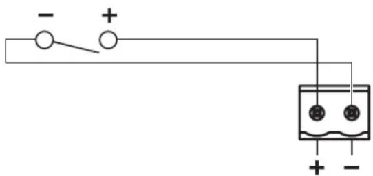
Mute with Standard Contact Closure
The amplifier is designed to mute all outputs either when the Mute contacts are shorted together, or when the Mute contacts are opened, depending on the amplifier configuration. The default state is Normally Open (NO), where a short across the Mute connector will mute all outputs. You can use the Mute DIP switch to invert the mute polarity to Normally Closed (NC), where an open circuit across the Mute connector will mute all outputs.
Note: All Output Limit LEDs will blink red when the amplifier is muted from the rear panel Mute connector.
text_image
- + 15 13 + -Importador en China: Bose Electronics (Shanghai) Company Limited, Level 6, Tower D, No. 2337 Gudai Rd. Minhang District, Shanghai 201100, China
natural_image
3D illustration of a black cable with two connectors (no text or symbols)text_image
OUTPUT ATTENUATION MUTE OUTPUT INPUT Amplink Input 1 2 3 4 5 6 7 8 9 10 CLASS 2 INPUT 1 INPUT 2 PHR 100 MHz PHR 100 MHz BASE Output Attenuation Power Supply Controller 100 MHz 100 MHznatural_image
Simple electrical circuit diagram with switch, battery, and power source (no text or symbols)natural_image
3D illustration of a black cable with two connectors (no text or symbols)www.Bose.com/compliance

Importeur aus China: Bose Electronics (Shanghai) Company Limited, Level 6, Tower D, No. 2337 Gudai Rd. Minhang District, Shanghai 201100
natural_image
3D illustration of a black cable with two connectors (no text or symbols)Netzkabel 111

CAT 5e-Kabel (1 m)
111

text_image
OUTPUT ATTENUATION MUTE OUTPUT ANDER INPUT 3111 TALL Amplitude Input 5 - 6 | 2 - 1 2 INPUT CLASS 2 WARNING 1 2 3 + 4 - ABSOLUTE INPUT AMplitude SELECT CRR LINK CRR LINK ADD ADD/RESET ADD/RESET ADD/RESET ADD/RESET ADD/RESET ADD/RESET ADD/RESET ADD/RESET ADD/RESET ADD/RESET ADD/RESET ADD/RESET ADD/RESET ADD/RESET ADD/RESET ADD/RESET ADD/RESET ADD/RESET ADD/RESET ADD/RESET ADD/RESET ADD/RESET ADD/RESET ADD/RESET ADD/RESET ADD/OFFSET ADD/RESET ADD/RESET ADD/RESET ADD/RESET ADD/RESET ADD/RESET ADD/RESET ADD/RESET ADD/RESET ADD/RESET ADD/RESET ADD/RESET ADD/RESET ADD/RESET ADD/RESET ADD/RESET ADD/RESET ADD/RESET ADD/RESET ADD/RESET ADD/RESET ADD/RESET ADD/RESET ADD/RESET ADD/SETT ADD/SETT ADD/SETT ADD/SETT ADD/SETT ADD/SETT ADD/SETT ADD/SETT ADD/SETT ADD/SETT ADD/SETT ADD/SETT ADD/SETT ADD/SETT ADD/SETT ADD/SETT ADD/SETT ADD/SETT ADD/SETT ADD/SETT ADD/SET TOUT / ADD / ADD / ADD / ADD / ADD / ADD / ADD / ADD / ADD / ADD / ADD / ADD / ADD / ADD / ADD / ADD / ADD / ADD / ADD / ADD / ADD / ADD / ADD / ADD / ADD / ADD / ADD / ADD / ADD / ADD / ADD / ADD / ADD / ADD / ADD / ADD / ADD / ADD / ADD / ADD / ADD / ADD / ADD / ADD / ADD / ADD / ADD / ADD / ADD / ADD / EDUATEnatural_image
Simple electrical circuit diagram with battery, switch, and two labeled terminals (no text or symbols)www.Bose.com/compliance

natural_image
Coiled black cable with two connectors (no text or symbols visible)text_image
OUTPUT ATTENUATION MUTE OUTPUT INPUT Amplink ADD INPUT ADD ADD ADD ADD ADD ADD ADD ADD ADD ADD ADD ADD ADD ADD ADD ADD ADD ADD ADD ADD ADD ADD ADD ADD ADD ADD ADD ADD ADD ADD ADD ADD ADD ADD ADD ADD ADD ADD ADD ADD ADD ADD ADD ADD ADD ADD ADD ADD ADD ADD 1 0 2 3 4 5 6 7 8 9 10 CLASS J WINDS 1 2 3 + 4 - ABB 1.0 1.1 1.2 1.3 1.4 1.5 1.6 1.7 1.8 1.9 2.0 2.1 2.2 2.3 2.4 2.5 2.6 2.7 2.8 2.9 3.0 3.1 3.2 3.3 3.4 3.5 3.6 3.7 3.8 3.9 4.0 4.1 4.2 4.3 4.4 4.5 4.6 4.7 4.8 4.9 5.0 5.1 5.2 5.3 5.4 5.5 5.6 5.7 5.8 5.9 6.0 6.1 6.2 6.3 6.4 6.5 6.6 6.7 6.8 6.9 7.0 7.1 7.2 7.3 7.4 7.5 7.6 7.7 7.8 7.9 8.0 8.1 8.2 8.3 8.4 8.5 8.6 8.7 8.8 8.9 9.0 9.1 9.2 9.3 9.4 9.5 9.6 9.7 9.8 9.9 10natural_image
Simple electrical circuit diagram with battery, switch, and two terminals (no text or symbols)Importeur in China: Bose Electronics (Shanghai) Company Limited, Level 6, Tower D, No. 2337 Gudai Rd. Minhang District, Shanghai 201100
Importeur in het VK: Bose Limited, Bose House, Quayside Chatham Maritime, Chatham, Kent, ME4 4QZ, United Kingdom Importeur in de EU: Bose Products B.V., Gorslaan 60, 1441 RG Purmerend, Nederland
Importeur In México: Bose de México, S. de R.L. de C.V., Paseo de las Palmas 405-204, Lomas de Chapultepec, 11000 México, D.F. Gegevens importeur en service-informatie: +52 55 52 02 35 45
Importeur in Taiwan: Bose Taiwan Branch, 9F-A1, No.10, Section 3, Minsheng East Road, Taipei City 104, Taiwan.
Telefoonnummer: +886 2 25 14 76 76
natural_image
Coiled black electrical plug with terminal connectors (no text or symbols visible)Netsnoer 111

Cat 5e-kabel (1 m) 111

2-pins Euroblock-connector (zwart) 111
3-pins Euroblock-connector (groen) 2 2 4
I-Share-jumper 112

www.Bose.com/compliance

Importer for Kina: Bose Electronics (Shanghai) Company Limited, Level 6, Tower D, No. 2337 Gudai Rd. Minhang District, Shanghai 201100
Importer for Storbritannia: Bose Limited, Bose House, Quayside Chatham Maritime, Chatham, Kent, ME4 4QZ, Storbritannia Importer I EU: Bose Products B.V., Gorslaan 60, 1441 RG Purmerend, Nederland
Importar I Mexica: Bose de México, S. de R.L. de C.V., Paseo de las Palmas 405-204, Lomas de Chapultepec, 11000 México, D.F. For informasjon om importer og service: +5255 (5202) 3545
Importer i Taiwan: Bose Taiwan Branch, 9F-A1, No. 10, Section 3, Minsheng East Road, Taipei City 104, Taiwan. Telefonnummer: +886-2-2514 7676
natural_image
Coiled black cable with two connectors (no text or symbols visible)Strømledning 111

Cat 5e-kabel (1 m)
111

text_image
OUTPUT ATTENUATION MUTE 1 2 OUTPUT SWITCH SETTINGS OUT ON POWER/THYKIN/DO NOT R/PREF/SURPLY NO REC SUPPORT TELC INPUT AMPLI#T INPUT AMP/CLK INPUT N/A N/A N/A N/A N/A N/A N/A N/A N/A N/A N/A N/A N/A N/A N/A N/A N/A N/A N/A N/A N/A N/A N/A N/A N/A N/A N/A N/A N/A N/A N/A N/A N/A N/AImporter — Chiny: Bose Electronics (Shanghai) Company Limited, Level 6, Tower D, No. 2337 Gudai Rd. Minhang District, Shanghai 201100
Importer — Wielka Brytania: Bose Limited, Bose House, Quayside Chatham Maritime, Chatham, Kent, ME4 4QZ, United Kingdom
Importer na terenie UE: Bose Products B.V., Gorslaan 60, 1441 RG Purmerend, Holandia
natural_image
3D rendering of a black cable with two connectors (no text or symbols visible)英国进口商:Bose Limited, Bose House, Quayside Chatham Maritime, Chatham, Kent, ME4 4Q7, United Kingdom
欧洲进口商 Bose Products B.V., Gorslaan 60, 1441 RG Purmerend, The Netherlands
墨西哥进口商:Bose de México, S. de R.L. de C.V., Paseo de las Palmas 405-204, Lomas de Chapultepec, 11000 México, DF.进口药和服务信息:+5255 (5202) 3545
natural_image
Simple electrical circuit diagram with battery, switch, and two terminals (no text or symbols)請閱讀並保管好所有安全和使用指示。
英國進口商:Bose Limited, Bose House, Quayside Chatham Maritime, Chatham, Kent, ME4 4Q7, United Kingdom
歐盟進口商 Bose Products B.V., Gorslaan 60, 1441 RG Purmerend, The Netherlands
墨西哥進口商:Bose de México, S. de R.L. de C.V., Paseo de las Palmas 405-204, Lomas de Chapultepec, 11000 México, D.F.進口商與服務資訊。+5255 (5202) 3545
This device complies with part 15 of the FCC Rules and with Industry Canada license-exempt RSS standard(s). Operation is subject to the following two conditions: (1) This device may not cause harmful interference, and (2) this device must accept any interference received, including interference that may cause undesired operation.
NOTE: This equipment has been tested and found to comply with the limits for a Class A digital device, pursuant to part 15 of the FCC Rules. These limits are designed to provide reasonable protection against harmful interference when the equipment is operated in a commercial environment. This equipment generates, uses, and can radiate radio frequency energy and, if not installed and used in accordance with the instruction manual, may cause harmful interference to radio communications. Operation of this equipment in a residential area is likely to cause harmful interference in which case the user will be required to correct the interference at their own expense.
Changes or modifications not expressly approved by Bose Corporation could void the user's authority to operate this equipment.
WARNING: This is a class A product. In a domestic environment this product may cause radio interference in which case the user may be required to take adequate measures.
Shielded cables are required to maintain regulatory compliance.
This product meets all EN55103-2 immunity requirements for E2 electromagnetic environment.
Initial turn on inrush current:
PZ1000A: 13.7 A (230 VAC 50 Hz), 7.6 A (120 VAC 50 Hz)
P4300A/P2600A: 14.4 A (230 VAC 50 Hz), 7.6 A (120 VAC 50 Hz)
Inrush current after AC mains interruption of 5 seconds:
PZ1000A: 8.2 A (230 VAC 50 Hz), 5.4 A (120 VAC 50 Hz)
P4300A/P2600A: 9.6 A (230 VAC 50 Hz), 6.1 A (120 VAC 50 Hz)
CE This product conforms to all applicable EU directive requirements. The complete declaration of conformity can be found at: www.Bose.com/compliance

www.Bose.com/compliance

This symbol means the product must not be discarded as household waste, and should be delivered to an appropriate collection facility for recycling. Proper disposal and recycling helps protect natural resources, human health and the environment. For more information on disposal and recycling of this product, contact your local municipality, disposal service, or the shop where you bought this product.

中国における輸入元: Bose Electronics (Shanghai) Company Limited, Level 6, Tower D, No. 2337 Gudai Rd. Minhang District, Shanghai 201100
英国における輸入元: Bose Limited, Bose House, Quayside Chatham Maritime, Chatham, Kent, ME4 4QZ. United Kingdom EUにおける輸入元: Bose Products B.V., Gorslaan 60, 1441 RG Purmerend, The Netherlands
Bose Corporation: 1-877-230-5639
natural_image
Coiled black electrical plug with terminal connectors (no text or symbols visible)AC電源コード111

Cat 5eケーブル (m)
111

natural_image
Simple electrical circuit diagram with battery, switch, and two terminals (no text or symbols)المعلومات التنظيمية
CAN ICES-3 (A)/NMB-3(A)
.www.Bose.com/compliance


جدول });
Rd. Minhang District- Shanghai 201100
ME4 4QZ: United Kingdom
Bose Taiwan Branch, 9F-A1, No. 10, Section 3, Minsheng East Road, Taipei City :
.104, Taiwan