VC 82 - Multimeter VOLTCRAFT - Free user manual and instructions
Find the device manual for free VC 82 VOLTCRAFT in PDF.

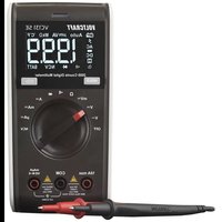
| Product type | Pen digital multimeter |
| Brand | Voltcraft |
| Model | VC 82 |
| Dimensions (L x W x H) | 230 mm x 35 mm x 20 mm |
| Weight (batteries included) | Approx. 140 g |
| Power supply | 2 LR44 / A 1.5 V button cell batteries |
| Typical battery life | Approx. 80 hours |
| Display | LCD 2000 counts (max. count 2000) |
| Input resistance (voltage) | Approx. 10 MΩ |
| Main measurement functions | DC/AC voltage up to 250 V, resistance up to 20 MΩ, continuity test (< 35 Ω), diode test |
| Range selection | Automatic with manual range hold |
| Data Hold function | Yes (holds measured value) |
| Auto power off | Yes, after 10 minutes of inactivity |
| Overvoltage categories | CAT II 250 V, CAT III 250 V |
| Operating conditions | 0 °C to 40 °C, humidity < 75 % RH (non-condensing) |
| Maintenance and cleaning | Clean, dry, antistatic, lint-free cloth; do not use abrasive or solvent-based products |
| Available spare parts | Test probes (including one 70 mm long), crocodile clip, replacement batteries |
| Repairability | User replaceable batteries and probes; no other repairs intended |
Frequently Asked Questions - VC 82 VOLTCRAFT
User questions about VC 82 VOLTCRAFT
0 question about this device. Answer the ones you know or ask your own.
Ask a new question about this device
Download the instructions for your Multimeter in PDF format for free! Find your manual VC 82 - VOLTCRAFT and take your electronic device back in hand. On this page are published all the documents necessary for the use of your device. VC 82 by VOLTCRAFT.
USER MANUAL VC 82 VOLTCRAFT
©NOTICE D'EMLPOI Page 42 - 61
GB These Operating Instructions accompany this product. They contain important information on setting up and using your Voltage Detector. You should refer to these instructions, even if you are buying this product for someone else.
Please retain these Operating Instructions for future use!
A list of the contents can be found in the Table of contents, with the corresponding page number, on page 23.
text_image
Diagram of a simple electrical circuit with a lamp, resistor, switch, and two probes labeled Gnatural_image
Illustration of a handheld electronic device connected to a resistor and two probes (no text or symbols)natural_image
Illustration of two electronic devices with a pen and a triangular symbol, no text or labels present.natural_image
Illustration of a simple electrical circuit with a pen, bulb, and variable resistor (no text or symbols)natural_image
Diagram of a missile or projectile with directional arrows indicating motion (no text or symbols)natural_image
Mechanical device with a control panel and directional arrow (no text or symbols)In purchasing this Voltcraft® product, you have made a very good decision for which we should like to thank you.
You have acquired an above-average quality product from a brand family which has distinguished itself in the field of measuring, charging and network technology by particular competence and permanent innovation.
With Voltcraft®, you will be equal to difficult tasks as an ambitious hot byist just as much as a professional user. Voltcraft® offers you reliable technology at an extraordinarily favourable cost-performance ratio.
We are certain: your start with Voltcraft will at the same time be the commencement of a long and profitable co-operation.
We wish you much enjoyment with your new Voltcraft® product!
Table of Contents
Introduction 23
Table of Contents ......23
Intended Use 24
Safety Instructions....25
Scope of supplies....29
Operating elements (see fold-out page) ......29
Taking measurements ....30
Servicing and cleaning 36
Disposal of flat batteries....38
Eliminating disturbances ....39
Disposal....39
Technical data and measuring tolerances....40
Intended Use
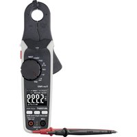
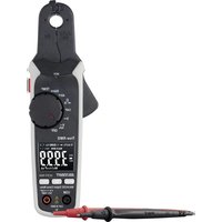
The Pentype multimeter is a digital measuring device with a LCD. The pen form allows the measured values to be read off while the measurement can be carried out with both hands.
The auto-range multimeter possesses the following measuring feature
- Measurement of direct and alternating voltage up to a maximum of 250 V
- Measurement of direct and alternating current up to a maximum of 400 mA (only VC-86)
- It is also designed to measure resistance values of up to 40 MOh (VC-82 bis 20 MOhm).
- Continuity check (< 35 Ohm acoustic) and diode test.
The measured impedance can be reduced to suppress phantom voltage values briefly (!) (only VC-86).
The measurement device may not be operated when it is open, i.e. with an open battery compartment or when the battery compartment cover is missing. Any measurement in moist rooms or outdoors or under adverse ambient conditions is not permitted.
The following are unfavourable ambient conditions:
- Excessive dampness or humidity
- Dust or combustible gases, vapours or solvents
- Electrical storms or stormy conditions and strong electrostatic fields, etc.
The pen-type multimeter may only be used in areas of the overvoltage category CATII to 250 V and CATIII to 250 V.
Use other than that described above can lead to damage to the product and may involve additional risks such as, for example, short circuits, fire, electrical shocks etc.
No part of the product may be modified or converted!
The safety instructions should be observed at all times!
Safety instructions

Please read through the operating instructions fully before setting up the system; they include important information for correct operation.
The guarantee iwill lapse if damage is incurred as a result of non-compliance with the operating instructions! We shall not be held liable for any consequential damage!
We do not accept any liability for personal injury or damage to property caused by incorrect handling or non-observance of the safety instructions! In such cases the guarantee will lapse.
This device left the factory in perfect condition in terms of safety engineering.
To maintain this status and ensure safe operation, you, as the user, must comply with the safety instructions and warnings contained in these instructions for use. The following symbols and notices must be observed:

Note! Read the instructions for use.
An exclamation mark in a triangle indicates important information in these operating instructions which are to be followed strictly.

This equipment is CE-tested and thus fulfils the EMC directive 89/336/EEC and the low-voltage directive 73/23/EEC.

Insulation class 2 (double insulated)
CATII Overvoltage category 2 for measurements on electrical devices in the household.
CATIII Overvoltage category 3 for measurements of the building installation.

Earth potential
A triangle containing a lightning symbol indicates risks which can lead to injury. These instructions must be followed strictly!

The hand symbol indicates useful tips which can help you when using the product.
For safety and licensing reasons (CE), unauthorised conversion and/or modification of the device is not permitted.
Consult suitably qualified staff, if you have doubts about how the equipment operates or about how to connect it safely.

Measuring devices and accessories are not toys and have no place in the hands of children.

In commercial institutions, the accident prevention regulations of the Employer's Liability Insurance Association for Electrical Systems and Operating Materials are to be observed.
In schools, training centres, computer and self-help workshops, handling of measuring devices must be supervised by trained personnel in a responsible manner.

Always make sure before measuring voltage that the measuring device is not in a currnet measuring area.

The voltage between the two measuring contacts of the measuring device and the earth may not exceed 250 V DC/AC in overvoltage category III or 250 V DC/AC in overvoltage category II.
Before changing the measuring area, the test prods have to be removed from the measured object.
Take particular care when dealing with voltages exceeding 25 V AC or 35 V DC. Even with voltages as low as these, it is possible to receive a life-threatening electric shock if you touch electric conductors.
Prior to each measurement, check your instrument including its measuring lines for damage. Never carry out measurements when the protective insulation is damaged (ripped, torn off etc.).

In order to avoid an electric shock, ensure that you do not touch the connections to be measured, even indirectly, during measurements.

Do not use the clamp-on ammeter just before, during or just after an electrical storm (electrical shock! / high-energy over-voltages!). Please make certain that your hands, shoes, clothing, the floor, the measuring device or the measurement lines switches and switching parts are absolutely dry.

Do not operate the measuring instrument in areas or unfavourable conditions where combustible gases, vapours or dust are or may be present. Avoid operation in the immediate vicinity of:
- strong magnetic or electromagnetic fields
- transmitting aerials or HF generators.
These could falsify the measured value.

If you have reason to assume that safe operation is no longer possible, then disconnect the appliance immediately and secure it against inadvertent operation. It can be assumed that safe operation is no longer possible if:
- the device shows signs of visible damage,
- the device no longer functions and
- it has been stored for longer periods under unfavourable conditions or
-following considerable stress during transportation.
Do not switch the measuring instrument on immediately after it has been taken from a cold to a warm environment. The condensation that occurs could destroy the device. Allow the device to reach room temperature before switching it on.

Do not leave the packaging material lying around carelessly. Plastic films and/or bags and polystyrene parts etc. may become dangerous toys in the hands of children.

Before opening it, disconnect the device from all voltage sources.
Capacitors in the device may still be charged, even if the device has been disconnected from all voltage sources. You should also heed the safety instructions in each chapter of these instructions.
Scope of delivery
Pen-typ multimeter with batteries
2 replacement button cells
1 replacement fuse (only VC-86)
1 replacement prod 70 mm in length
1 crocodile clamp (scew-on)
Carry bag
Operating instructions
Operating elements
(see fold-out page)
1 Test tip, screw-off (plus pole + at DC measurement)
2 Front covering flap with grip protection collar
3 Data hold button
4 Range Hold button
5 Select button
6 LCD
7 Low-impedance button (MAX button for VC-82)
8 Rear covering flap (battery compartment)
9 Connecting cable
10 On/Off switch
11 Bracket for testing prods-protection cap
12 Test prod (plus pole + at DC measurement)
Display symbols
AC alternating size for voltage and current
DC direct size for voltage and current

Momentary measuring range is maintained; no "automatic measuring range selection"

stands for data hold; the measuring figure is kept (e.g. for the record) until the "DH" button is or the multimeter is switched off.
OL
stands for overload; the measuring range has been exceeded

Battery replacement symbol; please replace the batteries immediately to avoid measuring errors!

Symbol for the diode test

Symbol for the acoustic continuity tester

Display of the measuring figure al analogue bar display (only VC-86)
Carrying out measurements

Never exceed the max. permitted input volumes in the overvoltage categories II or III (domestic and commercial area).
The frequency of the change volumes may not exceed 400 Hz!
Do not touch any circuits or circuit parts if voltages greater than 25 V ACrms or 35 V DC could be pend there! Danger to life!

Before measuring, check the measuring line for damage such as, for example, cuts, cracks or squeezing.
Defective measuring lines may no longer be used! Danger to life!
To guard against injury through the measuring prods on the pen-type there is a protection cap. This protection cap can be inserted when it has been removed into the safe-keeping opening (11) on the front.
Measuring prod selection
On the pen-type multimeter, the measuring prod can be replaced simply by the enclosed 70 mm second tip This is used fo measurement on lower lying measuring points.
Screw the measuring prod off in the anticlockwise direction and replace it with the long measuring prod.
The enclosed crocodile clamp can be screwed on the black measuring line.

Make sure when measuring the measuring prods that all voltage sources have been removed from the measuring device
Voltage measurement
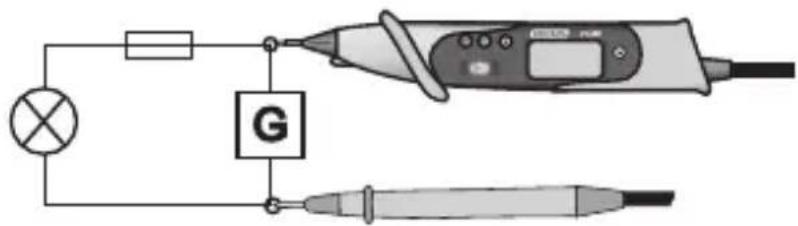
Proceed as follows to measure dc voltages:
text_image
Diagram of an electrical circuit setup with a lamp, resistor, galvanometer, and two probes connected to a power source.- Turn operating switch (10) to position "V"
- Now connect the two measuring prods to the object to be measured (battery, switch etc.).
- the polarity of the measuring figure concerned will be displayed in display together with the current measuring value in the display (6
To measure alternating voltage (AC), press button "S" (5) to change to the AC-rang. if you press it again, it will switch again to the DC measuring range.
The voltage range "V" shows an input resistance of approx. 10 MOhm. As soon as for direct voltages a minus "-" appears before the measuring figure, the measured voltage is negative (or the measuring prods have been interchanged).
"LI" Low Impedance 400 Ω (only VC-86)

This function may only be used for voltages of a max. of 250 V and a max. of 3 seconds!
This measuring function enables the reduction of the measuring impedance from 10 Ω to 400 Ω. through the reduction in the measuring impenace, possible phantom voltages are suppressed which could falsify the measuring result.
Press key "LI" (7) during the voltage measurment (max. 250 V) for a max. of 3 seconds. After release, the multimeter has the normal measuring impedance of 10 Ω.
Resistance measurement/continuity test

Make sure that all the circuit parts, switches and components and other objects of measurement are disconnected from the voltage at all times.
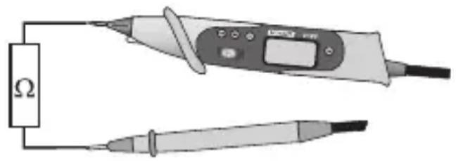
natural_image
Illustration of a power tool connected to a resistor and two probes (no text or symbols)Proceed as follows to measure resistance and for the acoustic continuity test:
- Turn range selection switch (10) to position "Ω"
- Check the measuring lines for continuity by connecting both measuring prods to one another. After that the resistance value must read approx. 0 Ohm.
- Now connect the measuring prods to the object to be measured. As long as the object to be measured is not high-resistive or is interrupted, the measured value will be displayed in the display (6).

When you carry out a resistance measurement, make sure that the measuring points which you contact with the measuring prods are free from dirt, oil, soldering vanish or similar Such circumstances can falsify the measured result
For the continuity check, press button "S" (5) until the symbol appears in the display. If you continue to press it, you will switch to the next measuring area (dode test, resistance, continuity ...).
As soon as "OL" appears in the display, you have exceeded the measuring area or the measuring circuit has been broken.
Diode test
For this measurement, proceed as follows:
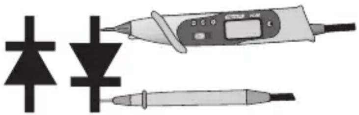
natural_image
Illustration of a soldering iron and its corresponding schematic symbol (no text or labels)- Switch area selection switch (10) to position 9.
- Press button "S"(5) twice to switch over to the diode test area. The diode symbol appears in the display.
- Now connect the two measuring prods with the object to be measured (diode). The conducting-state voltage is displayed.

If you test a diode in the conducting direction(rred measuring prod on the anode = diode side without ring marking), you will measure a voltage from approx. 0.6 V (silicon diode), as long as the diode route is not defective.
If you measure on the other hand in the blocked direction (red measuring line on the cathode = diode side with ring marking), "OL" will appear in the display.
If, on the other hand, a "voltage figure" is displayed, you have either connected the object to be measured incorrectly or it is defective.
Current measurement (only VC-86)
Currents of up to 400mA can be measured in the current measurement area. The current measurement area is secured and thus protected against overloading.
Proceed as follows to measure dc currents:
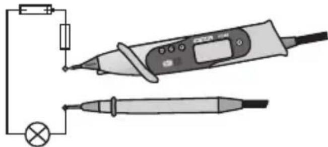
natural_image
Illustration of a simple electrical circuit with a pen, bulb, and variable resistor (no text or symbols)- Turn range selection switch (10) to position "A"
- The polarity of the measuring figure concerned will be displayed in the display together with the current measuring value in the display (6).
Proceed as follows to insert or measure alternating currents:
- Press button "S" (5) in the current measurement area, to change to the AC area; if you press it again, you will switch back to the DC area.
- The polarity of the measuring figure concerned will be displayed in the display together with the current measuring value in the display (6).

Never operate the measurement device when it is open.
Max-Hold Function (only VC-82)
The VC-82 has a MAX-Hold Function. If you press during a measuring the MAX button (7), the item shows automatically the highest measuring value on the LCD (6). To deactivate this funktion, press MAX button (7) again.
Auto-Power OFF function
So as not to reduce the service life of the battery unnecessarily, an automatic switch-off as been installed. The measuring device is switched off if no button is pressed for 10 minutes or the slide switch has not be oeprated. Simply by pressing any desired button (with the exception of "LI") the measuring device can be switched on again.
Servicing and cleaning
With the exception of replacing the fuse/battery and occasional cleaning, the pen-type multileter is maintenance-free. Use a clean, lint-free, antistatic and dry cloth to clean the device. Do not use any abrasive or chemical agents or detergents containing solvents.
Replacing the Fuse (only VC-86)
lef mo measure value is displayed any longer in the power measuring area, the fuse is presumably defective.
Proceed as follows to replace the fuse:
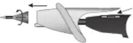
natural_image
Diagram of a missile or projectile with directional arrows indicating motion (no text or symbols)- Switch off the multimeter and remove the measuring device from all measuring circuits.
- Turnothe red measuring pond on the corrugated plastic ring in the anticlockwise direction and remove the prod.
- Remove the light-grey covering towards the front.
- Replace the defective fuse with a new fine-wire fuse (5 x 20 mm) the same type and rated current (F500mA, 250V)
- Close the pen-type multimeter again carefully in the reverse order

Make sure that only fuses of the type stated and rated current specified are used as a replacement. The use of repaired fuses or bridging the fuse bracket is not permitted.
Never operate the measurement device when it is open. !Danger to life!
Replacing the battery
If the battery symbol becomes visible in the display, she batteries have to be replaced as soon as possibl to prevent erroneous measurements.
Proceed as follows to replace the batteries:
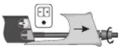
natural_image
Mechanical device with a control panel and directional arrow (no text or symbols)- Switch off the multimeter and remove the measuring device from all measuring circuits.
- Turn the grey corrugated plastic ring on the rear in the anticlockwise direction and detach it from the measuring devices.
- Remove the light-grey covering towards the rear.
- Rplace the flat batteries with new one of the same type (2xLR44). The batteries can be levered out of the battery holder at the side of the housing with a measuring prod or a sharp object.
- Close the pen-type multimeter again carefully in the reverse order.

Never operate the measurement device when it is open. !Danger to life!
Do not leave flat batteries in the device. Even batteries protected against leaking can corrode and thus release chemicals which may be detrimental to your health or destroy the battery compartment.

Lateral recesses have been provided in the housind for the spare batteries. These are covered securely by the light-grey covering. This means that your always have replacement batteries on hand.
Disposal of flat batteries.
You as the end consumer are legally obliged (Regulation on Flat Batteries) to return all used batteries and accumulators. Disposal in the household waste is prohibited!

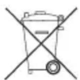
Batteries / accumulators which contain hazardous substances are marked by the symbols on the side. These symbols also indicate that it is prohibited to dispose of these batteries in the household waste.
The names for the decisive heavy metals are: Cd = cadmium, Hg = mercury, Pb = lead.
You can return flat batteries / accumulators free of charge to the collection points in your community, our branches or anywhere else where batteries or accumulators are sold.
Troubleshooting
By purchasing the digital multimeter, you have acquired a product which has been designed to the state of the art and is operationally reliable. Problems and malfunctions may, however, arise.
For this reason, we wish to describe to you here how you can eliminate possible disturbances easily yourself.

Always observe the safety instructions!
| Fault Possible cause | |
| The multimeter Are the batteries flat?does not function. Check the condition of the batteries. | |
| No measurement of Is the fuse for the current measure-current possible ment area defective?(only VC-86). Check the fuse(replacement of fuse) | |
| None measured Is the HOLD function active?value alteration.. Operatie the button "DH". | |

Repairs other than those just described should only be performed by an authorised electrician.
IOf you have queries about handling the measuring device, our technical support is available under the following telephone number:
Voltcraft, 92242 Hirschau, Tel. no. 0180 / 586 582 723 8
Disposal

If the product is no longer functional and can no longer be repaired, dispose of it in accordance with the relevant statutory regulations.
Technical data and measuring tolerances
Technical Data
Display reading. . . . . . . . . . . . . 3400 (VC-86), 2000 (VC-82) cou
Input resistance ..... approx. 10MOhm
Batteries . . . . . . . . . . . . . . . . . . 2x 1.5 V button cells LR44 /
Current consumption ..... approx. 2 mA
Operating period . . . . . . . . . . approx. 80 h
Working temperature ..... 0°C to 40°C
Storage temperature . . . . . . . -10°C to 50°C
Rel. humidity. . . . . . . . . . . . . . . < 75% (non-condensing)
from 0 to 30°C
Working height .... up to a max. of 2 000 m thro
Temp. for gar. accuracy ..... +18°C to +28°C
Weight incl. battery ..... approx. 140 g
Dimensions (LxWxH) ..... 230 mm x 35 mm x 20 mm
Measurement tolerances
Statement of accuracy in ± (% dof reading+ display error in digits (-dgt = no. of the smallest points)). The accuracy is valid for 1 year a temperature of +23°C +/-5°C, and at a relative humidity of less than 75 %, non-condensing.
Type of operation DC Volt
Range VC-82 Range VC-86 Accuracy Resolution
200,0 mV 400,0 mV ± (1,0% + 4 dgt) 0,1m V
2,000 V 4,000 V ± (1,3% + 3 dgt) 0,001 V
20,00 V 40,00 V ± (1,3% + 3 dgt) 0,01 V
200,0 V 250 V ± (1,3% + 3 dgt) 0,1 V
250 V - ± (1,5% + 3 dgt) 1 V
Overload protection 250 V; input resistance: 10 MΩ"
Type of operation AC Volt (40Hz to 400Hz)
Range VC-82 Range VC-86 Accuracy Resolution
200,0 mV - ± (1,8% + 40 dgt) 0,1mV
2,000 V 4,000 V ± (1,8% + 4 dgt) 0,001V
20,00 V 40,00 V ± (1,8% + 4 dgt) 0,01V
200,0 V 250,0 V ± (1,8% + 4 dgt) 0,1V
250 V - ± (1,8% + 8 dgt) 1V
"Overload protection 250 V; input resistance: 10 MΩ"
Type of operation DC A (only VC-86)
Range VC-82 Range VC-86 Accuracy Resolution
- 40,00 mA ± (2,0% + 2 dgt) 0,01 mA
- 400,0 mA ± (1,5% + 2 dgt) 0,1 mA
Overload protection 400mA 250 V fast blow fuse
Type of operation AC A 40 to 400 Hz (only VC-86)
Type of operation AC A 40 to 400 Hz (only VC-86)
Range VC-82 Range VC-86 Accuracy Resolution
- 40,00 mA ± (2,2% + 3 dgt) 0,01 mA
- 400,0 mA ± (2,5% + 3 dgt) 0,1 mA
Overload protection 400mA 250 V fast blow fuse
Type of operation Resistance
Range VC-82 Range VC-86 Accuracy Resolution
200,0 Ω 400,0 Ω ± (1,2% + 12 dgt) 0,1 Ω
2,000 kΩ 4,000 kΩ ± (2,0% + 5 dgt) 0,001 kΩ
20,00 kΩ 40,00 kΩ ± (2,0% + 5 dgt) 0,01 kΩ
200,0 Ω 400,0 kΩ ± (2,0% + 5 dgt) 0,1 kΩ
2,000 MΩ 4,000 MΩ ± (3,0% + 2 dgt) 0,001 MΩ
20,00 MΩ 40,00 MΩ ± (5,0% + 2 dgt) 0,01 MΩ
Overload protection 500 V
Continuity tester: acoustic signal for resistances < 35 Ω
"Diode test: Testing voltage max. 3,4V; Display ""OL"" > 2 V"

Attention!
In no event exceed the max. permitted input volumes. Do not contact circuits or parts of circuits if there could be higher voltages pending within them than 25 V ACrms or 35 V DC! Danger to life!
F Introduction
Cher(e) client(e),
text_image
Diagram of a simple electrical circuit with a lamp, resistor, switch, and two probes connected to a device labeled 'G'.natural_image
Illustration of a simple electrical testing setup with a resistor and two probes (no text or symbols)natural_image
Illustration of a soldering iron and its corresponding circuit symbol (no text or labels)natural_image
Illustration of a simple electrical circuit with a power source, switch, and two probes (no text or symbols)natural_image
Diagram of a mechanical component with directional arrows indicating motion or force (no text or symbols)natural_image
Mechanical device with a control panel and directional arrow (no text or symbols)© Copyright 2011 by Voltcraft®
GBImpressum /legal notice in our operating instructions
These operating instructions are a publication by Voltcraft®, Lindenweg 15, D-92242 Hirschau/Germany, Phone +49 180/586 582 7 (www.voltcraft.de).
All rights including translation reserved. Reproduction by any method, e.g. photocopy, microfilming, or the capture in electronic data processing systems require the prior written approval by the editor. Reprinting, also in part, is prohibited.
These operating instructions represent the technical status at the time of printing. Changes in technology and equipment reserved.
© Copyright 2011 by Voltcraft®
© Copyright 2011 by Voltcraft®
V6_1111_01/HD