
DE 9 XL - Heating Heylo - Free user manual and instructions
Find the device manual for free DE 9 XL Heylo in PDF.

| Product type | Electric heater, portable hot air generator |
| Brand | Heylo |
| Model | DE 9 XL |
| Total power | 9000 W |
| Heating power (level 1 / level 2) | 4500 W / 9000 W |
| Motor power | 52 W |
| Power supply | 400 V / 50 Hz, 16 A, CEE plug |
| Maximum current | 13 A (heating) |
| Air flow | 550 m³/h |
| Thermostat temperature range | 0 °C to 40 °C |
| Dimensions (L × W × H) | 466 mm × 322 mm × 420 mm |
| Weight | 14.5 kg |
| IP protection rating | IP21 |
| Main functions | Cold air ventilation, 2-level heating (4500 W / 9000 W) |
| Usage | Spot heating or enclosed rooms, horizontal operation only |
| Safety devices | Safety temperature limiter (STB), automatic shutdown at set temperature, after-cooling function |
| Maintenance and cleaning | Clean the heating coil with compressed air if necessary. Do not cover the device. |
| Spare parts and repairability | List of 31 available spare parts (HEYLO references). Repairs by qualified electrician or HEYLO. |
| Standards applied | DIN VDE 0700, EN 60335-1/2-30, EN 55014-1 |
| Warranty | Excluded if instructions in the manual are not followed |
Frequently Asked Questions - DE 9 XL Heylo
User questions about DE 9 XL Heylo
0 question about this device. Answer the ones you know or ask your own.
Ask a new question about this device
Download the instructions for your Heating in PDF format for free! Find your manual DE 9 XL - Heylo and take your electronic device back in hand. On this page are published all the documents necessary for the use of your device. DE 9 XL by Heylo.
USER MANUAL DE 9 XL Heylo
EC Declaration of Conformity IIA In conformity with EC Machine Directive 2006 / 42 / EC
For unit series: Electric heating appliances
Type: DE 9 XL
HEYLO GmbH of Im Finigen 9, D-28832 Achim, Germany, declares that, if they are fitted, maintained and used in conformity with the operating instructions and the generally accepted engineering standards, the machines mentioned are in keeping with the fundamental safety and health requirements of the "Machine Ordinance" as well as with the regulations and standards mentioned hereinafter.
Applicable EC directives:
EC Machinery Directive 2006/42/EG
Low Voltage Directive 2014/35/EU
EMC Directive 2014/30/EU
In case of unauthorised changes of the machine, the directives shall forfeit their validity.
Applied standards:
DIN VDE 0700 Part 1 and Part 30
DIN EN 55014-1:2012-05
EN 60 335-1
EN 60 335-2-30
Achim, 18 July 2016
Dr. Thomas Wittleder
- Managing Director -
Table of contents
- General information 9
- Safety instructions 9
- Operation 9
- Installation guidelines 10
- Technical Data 11
6.Troubleshooting 11
7.Circuit diagram 12 - Spare parts list. 13
1. General information
CAUTION: Read carefully before starting up!
Please observe the notes in the operating instructions carefully. In case of non-observation, the warranty claims will become void. The manufacturer shall not be liable for any damage and/or consequential damage resulting.
The DE series electric heaters are light, easily transportable producers of warm air. The heat output of the DE 9 XL can be adjusted at 2 levels. The amount of air cannot be adjusted. Connecting air pipes to the device is not permitted. The device can be used for ventilation and heating.
The electric heaters are suitable for spot heating (e.g. of machines or work places) and for heating closed rooms. They have been designed to be used in a horizontal position.
The device may as well be applied for ventilation of small areas.
The appliance is fitted with a thermostat (Switching range +5^ to +40^ )
An external room thermostat cannot be connected to it.
2. Safety instructions
- To avoid overheating or a fire hazard, do not cover the heating from.
- Do not connect the appliance to the mains power socket if the voltage given on the rating plate differs from the mains voltage.
Children should be supervised to ensure that they do not play with the appliance. If the appliance is damaged, do not use it any more. - If you notice any damage to the unit or power cord, remove the heater off immediately.
- Do not use the heater in a bathtub, shower or near a swimming pool
3. Operation
Mains connection: 400V / 50Hz /16 A CEE
Starting up:
- CEE-plug into the suitable socket. (Neutral required)
- function choice (heating or cold-ventilation)
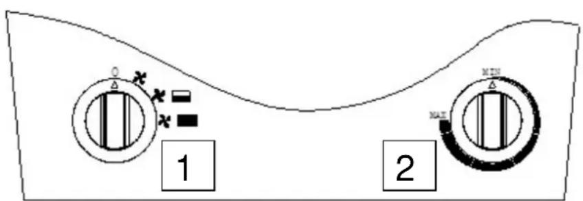
Switch 1 (heating)
0 = off
1 = cold-ventilation
2 = 4500W
3 = 9000W
When the switch 1 is connected to a heating mode, the heater will automatically shut off when reaching the set temperature (switch 2). The fan continues operating for better air circulation.
After shutting off, the fan will continue until no more residual heat is present (after-cooling function).
When the switch 1 is switched on ventilation is, only the fan motor.
Switch 2 (temperature thermostat)
In the heating mode to regulate the room temperature between 5^ and 40^ is possible
Switching off
After switching off, then have to wait until the fan turns off. Only then should the plug be pulled.
4. Installation guidelines
1. Place of installation
The appliances cannot be operated at place where there are ignitable gas, air or gas/air combinations (e.g. petrol pumps, paint workshops, etc.) and also not where they can suck in small combustible parts, that can be lighted up at the heating coil and blown out as glowing sparks (e.g. straw, paper, sawdust and wood shavings, etc.)
The appliance cannot be connected to air conduits or hoses. The device should not be exposed to heavy dust emissions. Dust deposits on the PTC heating element can cause a short circuit in connection with humidity.
2. Installation
Electric heaters cannot be operated in the immediate proximity of bathtubs, wash basins or swimming pools.
3. Safety distances to combustible parts:
On the side: 0.60m Blow out side: 2.00m
Suctioning side: 0.20m Upwards: 2.00m
Do not cover electric heaters with textiles!
Floors and ceilings must be fire resistant. Suctioning and blowing out pipes should not be narrowed.
- When using on a construction site, the safety guidelines of the professional construction associations must be maintained.
- When using in agriculture, the regulations of the agricultural professional associations and property insurers apply.
- Legislation: the following regulations must be observed when installing and starting up:
Work place directive ASR 5
Accident prevention regulations VBG 43
available at: German Information Centre for Technical Regulations (DITR) at DIN, Burggrafenstraße 6, 10787 Berlin).
- The appliance cannot be operated under wall sockets.
- The appliance cannot be operated by a programmable timer without supervision.
5. Technical Data
| Type | DE 9 XL | |
| Total output | W | 9000 |
| Heat output (level 1 / level 2) | W | 4500 / 9000 |
| Motor output | W | 52 |
| Control possibility | °C | 0° - 40° |
| Voltage | V | 400 |
| Electricity (ventilate / level 1 / level 2) | A | 6,5 / 13 |
| Air volume | m³ / h | 550 |
| IP class | 21 | |
| Length x width x height | mm | 466 / 322 / 420 |
| Weight | kg | 14,5 |
6. Troubleshooting
| ERROR | CAUSE | SOLUTION |
| Appliance does not start up | 1. Main switch switched off2. Indoor fuses tripped.3. Internal fuse (13A) has been activated.4. Plug has been pulled out of the main switch panel or extension cable.5. Supply line defective. | Check up to what point electricity is available. Repair defect. |
| 6. Mains switched off | Wait until electricity returns. Check safeguards. | |
| 7. Safety temperature limiter tripped | Appliance was overheated. Repair source of error and the appliance will switch itself on again after waiting for a while. | |
| 8. Indoor residual-current-circuit breaker trips. | Clean heating coil (possibly with compressed air) otherwise send it to be repaired. Appliance could have come into contact with moisture. If yes, let it dry thoroughly before operating it. | |
| 9. Heating coil defective. | Send appliance to be repaired | |
| Appliance heats up, fan does not run | 10. Fan defective | Send appliance to be repaired |
If the appliance is supplied with electricity by the mains cable, work to the electrical system can only be carried out by specialist electrical staff or a person trained in electrical appliances in accordance with VBG 4.
Please only get repair work to the electrical appliance done by HEYLO service partners.
Discontinuing use and disposal of the appliance
The appliance has been designed for long term use.
If it has to be disposed of, please do so in accordance with the current relevant laws in an environment friendly manner.
7. Circuit diagram
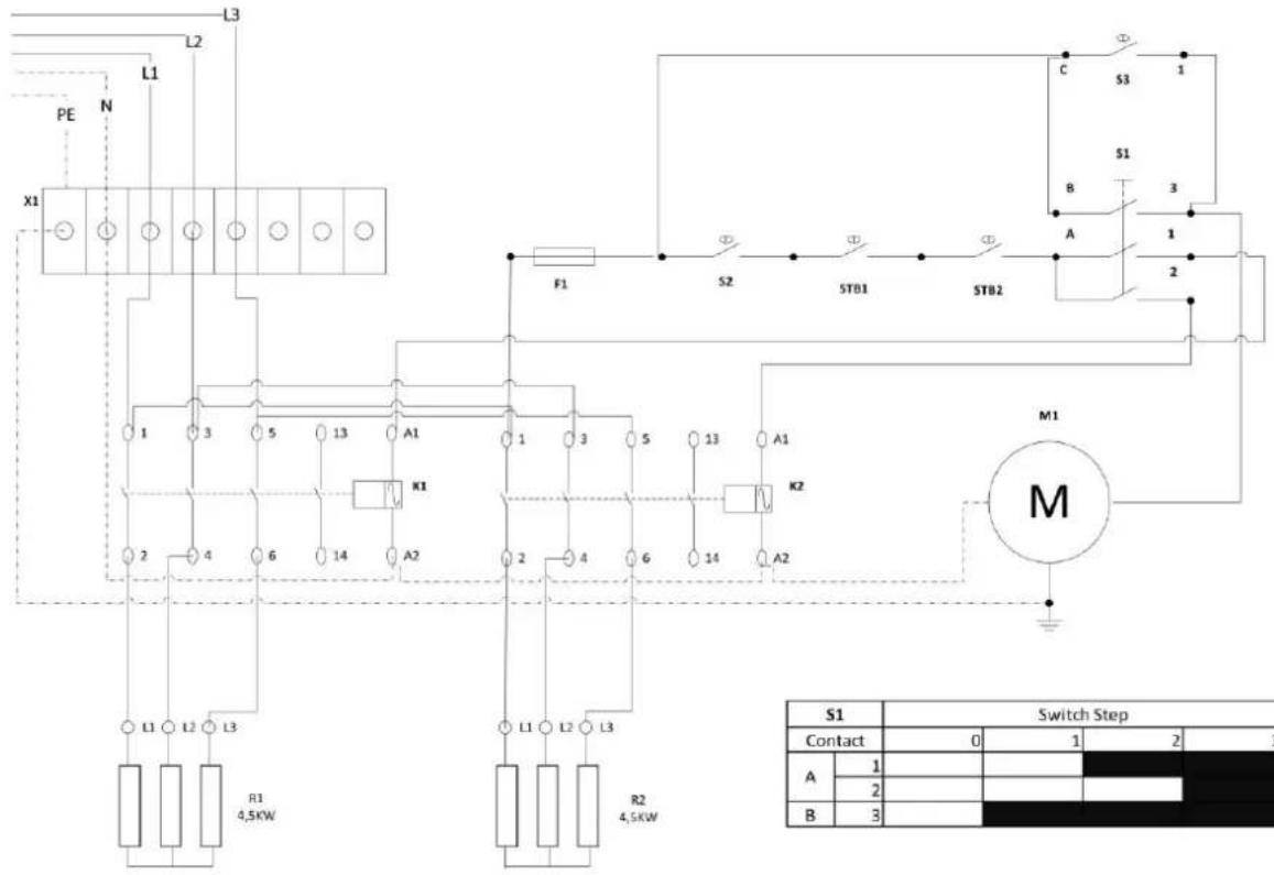
16A 400V 50Hz 3P+N
| S1 | Switch Step | ||||
| Contact | 0 | 1 | 2 | 3 | |
| A | 1 | ||||
| 2 | |||||
| B | 3 | ||||
| S1 | Hauptschalter | mainswitch | 0-1-2-3 |
| S2 | Raum Thermostat | room thermostat | 0 – 40° |
| S3 | Nachlaufthermostat | trailing thermostat | 40°C |
| STB1 | STB Output | safety temperature limiter (Output) | 140° |
| STB2 | STB Heizelement | safety temperature limiter (heating element) | 110° |
| F1 | Sicherung | fuse | 3A |
| K1 | Schütz 1. Heizstufe | connactor 1st heat stage | |
| K2 | Schütz 2. Heizstufe | connactor 2nd heat stage | |
| R1 | Heizung 1 | heating resistance 1 | 4,5KW |
| R2 | Heizung 2 | heating resistance 2 | 4,5KW |
| X1 | Reihenklemme | terminal | |
| M1 | Ventilatormotor | blower motor |
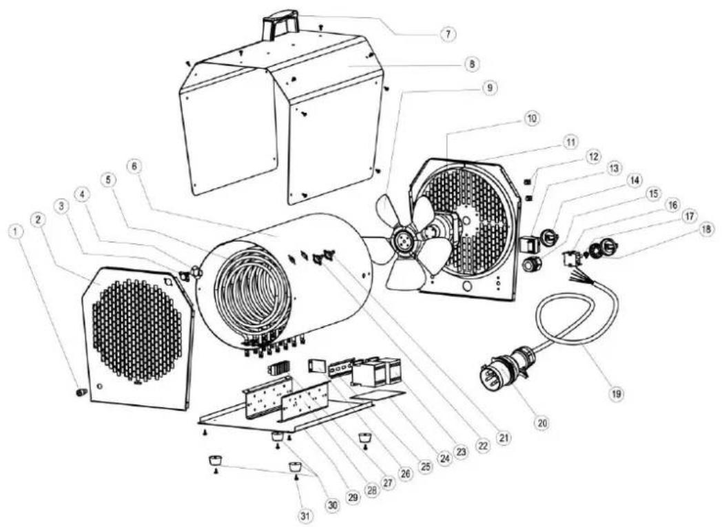
- Spare parts list
| Pos. | HEYLO - Art.-No. | Bezeichnung |
| 1 | 1760911 | Fuse assemble |
| 2 | 1760912 | Front grill assemble |
| 3 | 1760913 | Protector 1 |
| 4 | 1760914 | Fixed board for thermostat |
| 5 | 1760915 | Heating element |
| 6 | 1760916 | Air ventilator |
| 7 | 1760917 | Handle |
| 8 | 1760918 | Haousing |
| 9 | 1760919 | Fan blade |
| 10 | 1760920 | Motor |
| 11 | 1760921 | Back grill assemble |
| 12 | 1760922 | Sensor supporter |
| 13 | 1760923 | Adjustable thermostat |
| 14 | 1760924 | Knob assemble |
| 15 | 1760925 | Fixed head for cable |
| 16 | 1760926 | Switch |
| 17 | 1760927 | Fixed part für switch |
| 18 | 1760928 | Ring |
| 19 | 1760929 | Cable |
| 20 | 1760930 | Five pin plug |
| 21 | 1760931 | Protector 2 |
| 22 | 1760932 | Time-delay thermostat |
| 23 | 1760935 | AC contactor |
| 24 | 1760940 | Insulation board |
| 25 | 1760939 | Rail |
| 26 | ||
| 27 | 1760933 | Connection terminal |
| 28 | 1760934 | Fixed board for relay |
| 29 | 1760936 | Bottom board |
| 30 | 1760937 | Rubber feet |
| 31 | 1760938 | Screw |
Directives CE pertinentes:
Directive des machines 2006/42/EG
SIE HABEN FRAGEN? WIR HELFEN IHNEN GERN! Do you have any questions? We are happy to help you!
HEYLO Kundendienst - Technischer Support und Service
HEYLO Customer Service - Technical Support and Service
Tel. +49 (0) 42 02 - 97 55 15