
T91A64 - Mounting bracket AXIS - Free user manual and instructions
Find the device manual for free T91A64 AXIS in PDF.
| Product type | Angle mount bracket for network camera |
| Brand | Axis |
| Model | T91A64 |
| Dimensions (L x H x D) | 345 x 200 x 185 mm (13.6 x 8 x 7.3 in.) |
| Weight | 1250 g (2.8 lb) |
| Maximum load | 15 kg (33 lb) |
| Material | Aluminum |
| Color | NCS S 1002-B (off-white) |
| Mounting hole diameter | 10 mm (0.4 in.) |
| Required accessories (not included) | AXIS T91A61 wall mount and bracket mounting device |
| Screws included | 4 M8x22 screws |
| Installation type | Angle mounting for Axis network camera |
| Intended use | Mounting camera on an exterior or interior corner |
| Care and cleaning | Clean with a soft dry cloth. Do not use abrasive products. |
| Safety | Follow local laws and regulations during installation. |
| Spare parts and repairability | No specific spare parts. In case of issues, contact Axis support. |
| General information | This bracket requires the AXIS T91A61 wall mount (sold separately) for full installation. |
Frequently Asked Questions - T91A64 AXIS
User questions about T91A64 AXIS
0 question about this device. Answer the ones you know or ask your own.
Ask a new question about this device
Download the instructions for your Mounting bracket in PDF format for free! Find your manual T91A64 - AXIS and take your electronic device back in hand. On this page are published all the documents necessary for the use of your device. T91A64 by AXIS.
USER MANUAL T91A64 AXIS
AXIS T91A62 Parapet Mount
AXIS T91A63 Ceiling Mount
AXIS T91A64 Corner Mount
AXIS T91A67 Pole Mount
About this Document
This document includes instructions for installing the AXIS T91A Mounting Accessories.
Equipment Modifications
This equipment must be installed and used in strict accordance with the instructions given in the user documentation.
Liability
Every care has been taken in the preparation of this document. Please inform your local Axis office of any inaccuracies or omissions. Axis Communications AB cannot be held responsible for any technical or typographical errors and reserves the right to make changes to the product and documentation without prior notice. Axis Communications AB makes no warranty of any kind with regard to the material contained within this document, including, but not limited to, the implied warranties of merchantability and fitness for a particular purpose. Axis Communications AB shall not be liable nor responsible for incidental or consequential damages in connection with the furnishing, performance or use of this material.
Support
Should you require any technical assistance, please contact your Axis reseller. If your questions cannot be answered immediately, your reseller will forward your queries through the appropriate channels to ensure a rapid response. If you are connected to the Internet, you can:
• find answers to resolved problems in the FAQ database. Search by product, category, or phrases
- report problems to Axis support by logging in to your private support area.
AXIS T91A Mounting Accessories
This installation guide provides instructions for installing the wall/parapet/ceiling/corner/pole mounting accessories for Axis network cameras. For all other aspects of using the Axis network camera, please see the Installation Guide and User's Manual, available from www.axis.com
Installation steps
- Check the package contents against the list below
- Hardware overview. See page 4
- Install the hardware:
• Install the AXIS T91A61 Wall Mount, see page 6
• Install the AXIS T91A62 Parapet Mount, see page 7
• Install the AXIS T91A63 Ceiling Mount, see page 9
• Install the AXIS T91A64 Corner Mount, see page 11
• Install the AXIS T91A67 Pole Mount, see page 12
Important!
This product must be used in compliance with local laws and regulations.
1 Package contents
| Model Item | |
| AXIS T91A61 Wall Mount | Wall bracketBracket holder |
| AXIS T91A62 Parapet Mount | Parapet bracketBracket holder |
| AXIS T91A63 Ceiling Mount | Ceiling bracketBracket holder |
| AXIS T91A64 Corner Mount | Corner bracket (AXIS T91A61 required)4 M8x22 screws |
| AXIS T91A67 Pole Mount | Pole bracketSteel straps (steel strap tool not supplied) |
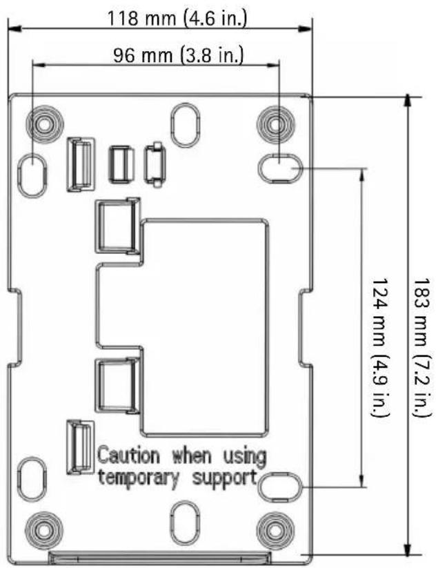
② Hardware overview
Note:
Some installations may require the supplied pendant adapter to be replaced which is done by loosening the stop screw and unscrewing the adapter. In this case, refer to the Installation Guide included with the pendant kit.

Install the Hardware
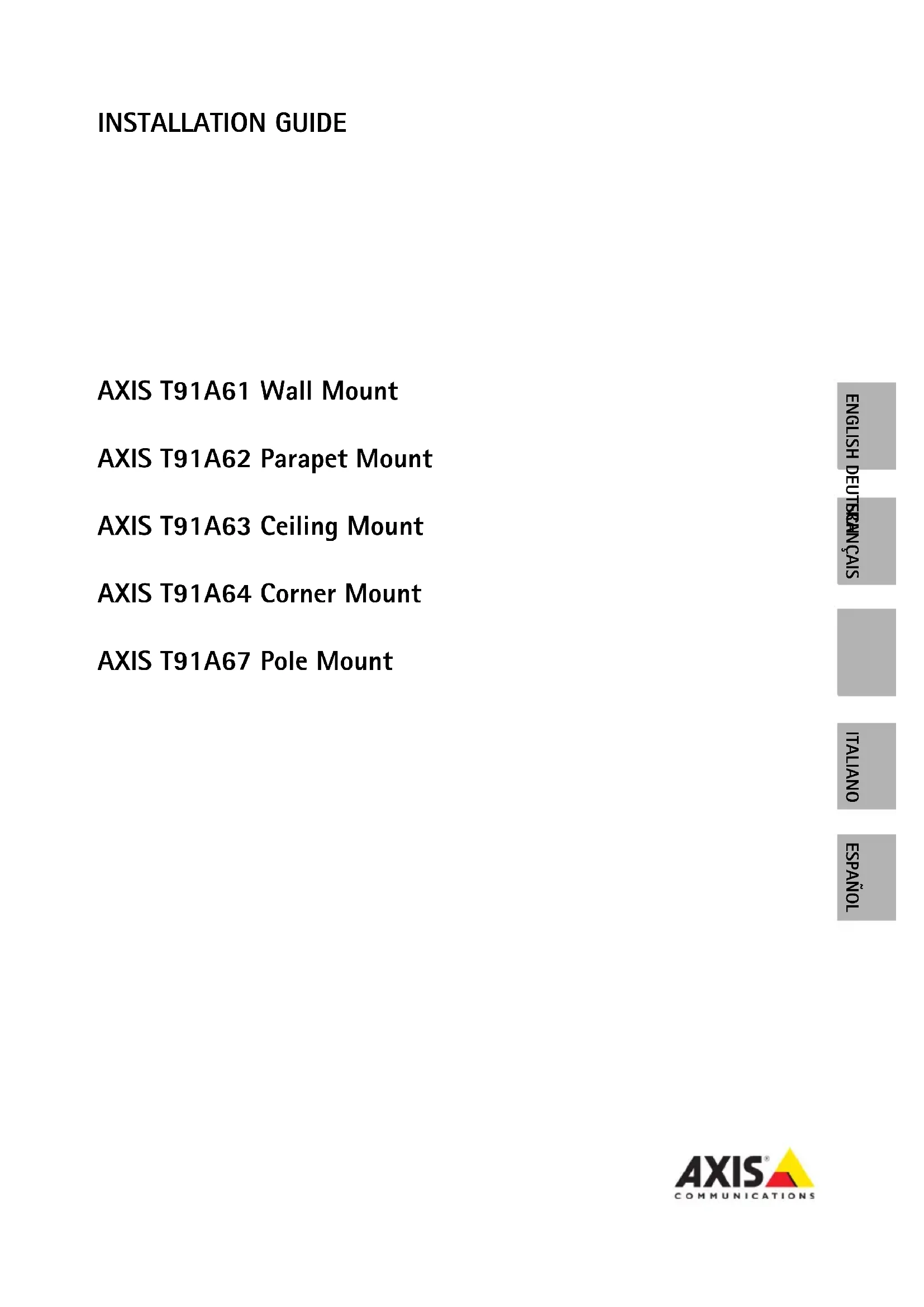
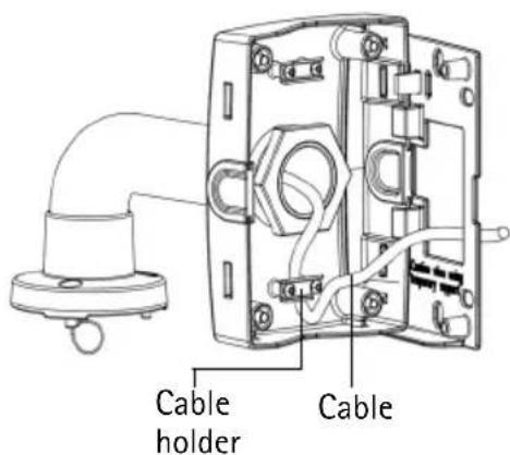
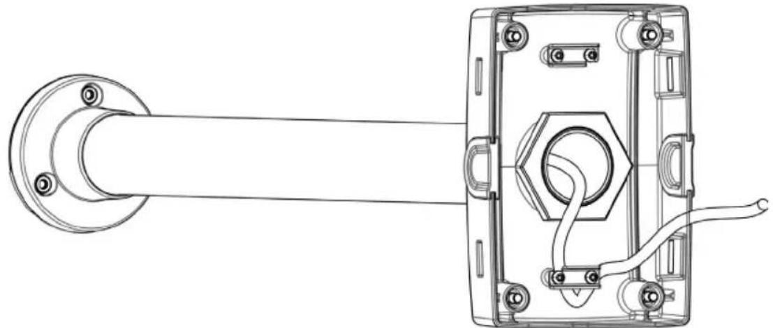
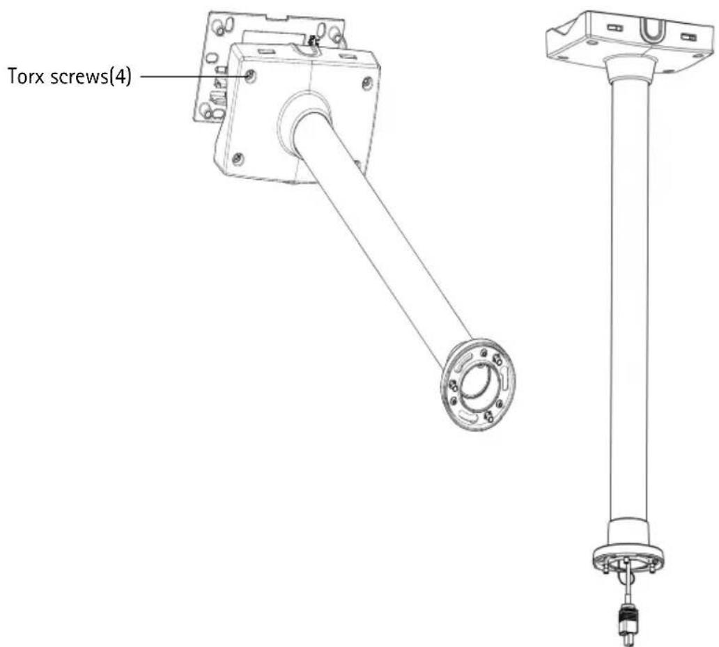
Install the AXIS T91A61 Wall Mount
-
Refer to Hardware overview, on page 4 for information on the supplied parts.
-
Route the network cable through or along the wall.
-
Attach the bracket holder in the desired position using screws that are appropriate for the wall material and the weight of the camera and bracket.
-
The wall bracket can temporarily be hooked on the bracket holder, in order to easily route the cable through the bracket:
natural_image
3D rendering of a metallic pipe fitting with mounting flanges (no text or symbols)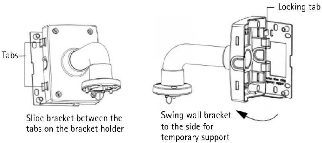
- Route the necessary cables through the wall bracket, securing them in the cable holder.
-
Pull the locking tab and unhook the wall bracket from the temporary position.
-
Use the Torx screws to secure the wall bracket to the bracket holder.
-
Refer to the Installation Guide for the network camera for instructions on how to attach the camera to the bracket.
Install the AXIS T91A62 Parapet Mount
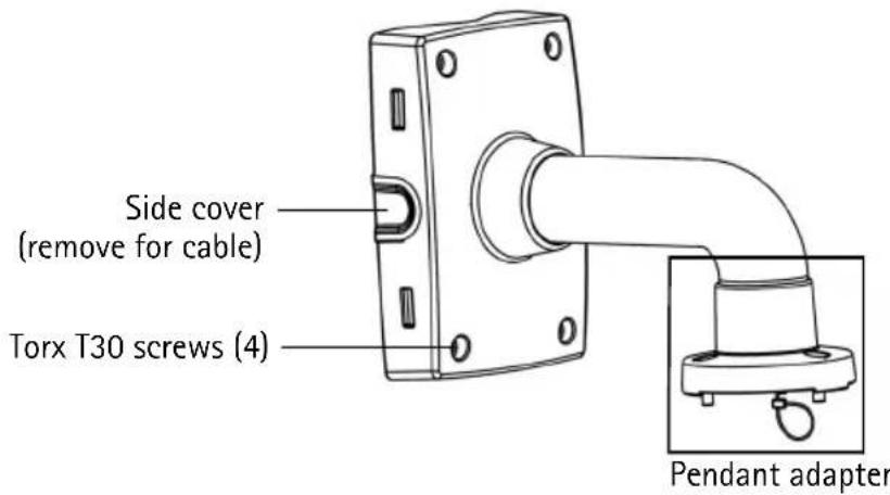
- Refer to Hardware overview, on page 4 for information on the supplied parts.
- Route the network cable through or along the roof.
- Attach the bracket holder in the desired position on the roof using screws that are appropriate for the material and the weight of the camera and bracket. Install the bracket maximum 80 mm (3.2 in.) from the edge of the roof for the camera's outer diameter to be aligned with the edge of the roof. Maximum weight allowed 15 kg (33 lbs).
- Route the necessary cables through the parapet bracket, securing them in the cable holder.
natural_image
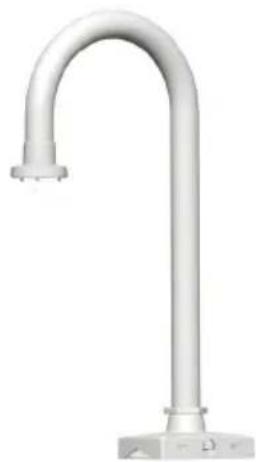
White cylindrical pipe fitting with a flanged end, mounted on a base (no text or symbols visible)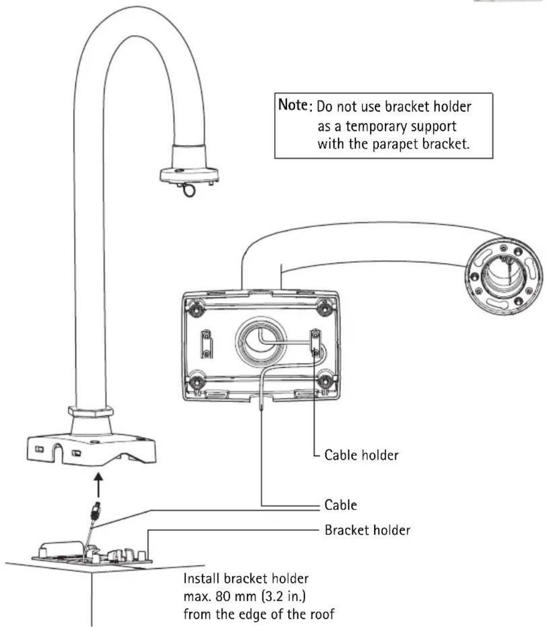
-
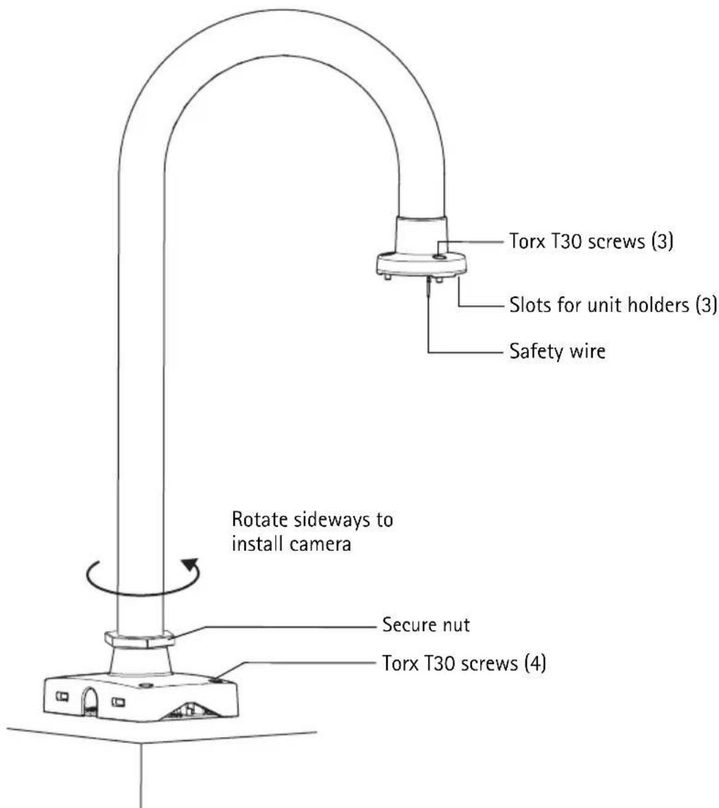
Use the Torx screws to secure the parapet bracket to the bracket holder.
-
Rotate the bracket and tighten the secure nut to lock the bracket in a sideways position. The camera can now be installed safely rather than hanging over the edge of the roof. The secure nut is loose at delivery for this purpose.
-
Refer to the Installation Guide for the network camera for instructions on how to attach the camera to the bracket.
-
Rotate the bracket into position and tighten the secure nut firmly.
Notes:
- Some installations may require the supplied pendant adapter to be replaced, which is done by loosening the stop screw and unscrewing the adapter. In this case, refer to the Installation Guide included with the pendant kit.
Install the AXIS T91A63 Ceiling Mount
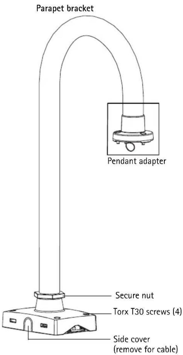
- Refer to Hardware overview, on page 4 and page 5 for information on the supplied parts.
- Route the network cable through or along the ceiling.
- Attach the bracket holder in the desired position in the ceiling using screws that are appropriate for the ceiling material and the weight of the camera and bracket. Maximum weight allowed 15kg (33lbs).
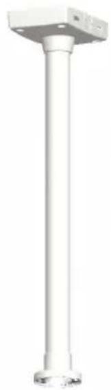
natural_image
Pure white cylindrical mechanical component with a square top and flanged base (no text or symbols)- Route the necessary cables through the ceiling bracket, securing them in the cable holder.
natural_image
Technical line drawing of a mechanical assembly with a flanged shaft and internal components (no text or symbols)- Use the Torx screws to secure the ceiling bracket to the bracket holder.
- Refer to the Installation Guide for the network camera for instructions on how to attach the camera to the bracket.
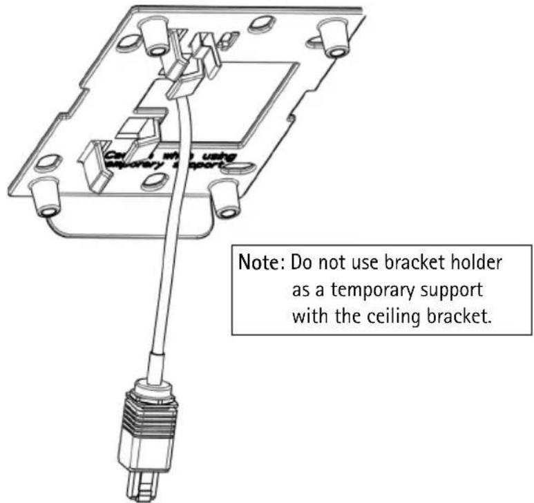
Install the AXIS T91A64 Corner Mount
-
Refer to Hardware overview, on page 4 for information on the supplied parts.
-
Attach the corner bracket in the desired position using screws that are appropriate for the wall material and the weight of the camera and bracket.
-
Attach the bracket holder (not included) to the corner bracket using the supplied screws.
-
The wall bracket (not included) can temporarily be hooked on the bracket holder, in order to easily route the cable through the bracket:
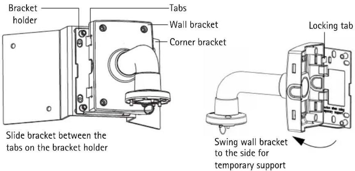
Note:
The bracket holder and wall bracket (AXIS T91A61) are required for the installation but must be purchased separately, see the table in Package contents, on page 3.
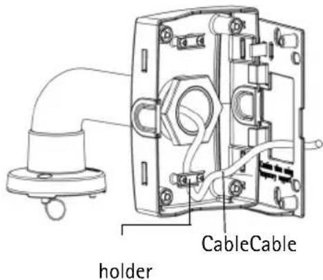
- Route the necessary cables through the wall bracket, securing them in the cable holder.
-
Press the locking tab and unhook the wall bracket from the temporary position.
-
Use the Torx screws to secure the wall bracket to the bracket holder.
-
Refer to the Installation Guide for the network camera for instructions on how to attach the camera to the bracket.
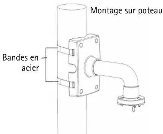
Install the AXIS T91A67 Pole Mount
-
Refer to Hardware overview, on page 4 and page 5 for information on the supplied parts.
-
Route the necessary cables through the bracket, securing them with the cable holder.
-
Use the supplied steel straps to attach the bracket to the pole and tighten with a steel strap tool (not supplied).
natural_image
Pure diagram of a pipe fitting with mounting bracket and side connectors (no text or symbols)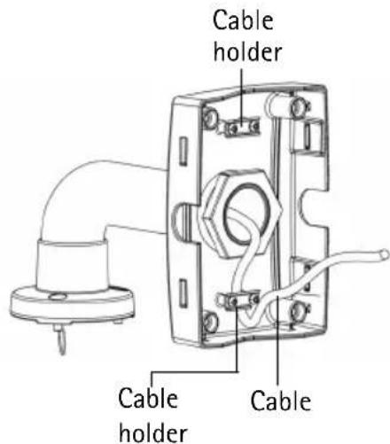
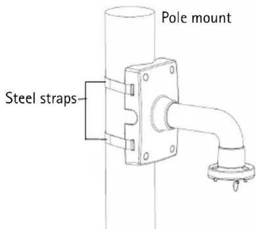
- Refer to the Installation Guide for the network camera for instructions on how to attach the camera to the bracket.
Technical Data
| AXIS T91A61 Wall Mount | AXIS T91A62 Parapet Mount | AXIS T91A63 Ceiling Mount | AXIS T91A64 Corner Mount | AXIS T91A67 Pole Mount | |
| Size W x H x D mm (in.) | 140 x 200 x 270 (5.6 x 8 x 10.7) | 470 x 754 x 138 (18.5 x 29.7 x 5.4) | 195 x 750 x 138 (7.7 x 29.5 x 5.4) | 345 x 200 x 185 (13.6 x 8 x 7.3) | 140 x 200 x 270 (5.6 x 8 x 10.7) |
| Weight g (lbs) | 1450 (3.2) 2900 (6.4) | 2000 (4.4) 1250 (2.8) | 1220 (2.7) | ||
| Max. weight supported kg (lbs) | 15 (33) 15 (33) 15 (33) | 15 (33) 15 (33) 15 (33) | |||
| Material | Aluminum Aluminum | Aluminum Aluminum | Aluminum Aluminum | ||
| Color code | NCS S 1002-B NCS S 1002-B NCS S 1002-B NCS S 1002-B | ||||
| Mounting holes diameter mm (in.) | 9 (0.35) | 9 (0.35) | 9 (0.35) 10 (0.4) | - | |
| Pole size mm (in.) | - | - | - | 80–150 (3–6) | |
Bracket holder
natural_image
3D rendering of a metallic pipe fitting with mounting flanges (no text or symbols)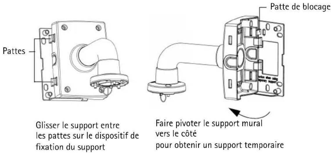
natural_image
White cylindrical pipe with a flanged end and base, no text or symbols visible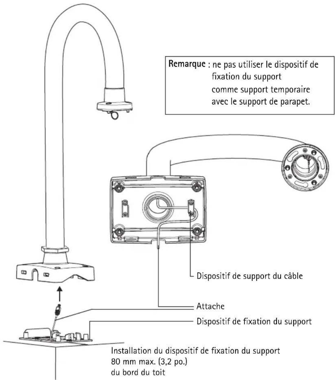
natural_image
Pure white cylindrical mechanical component with mounting holes, no text or symbols visiblenatural_image
Technical line drawing of a mechanical assembly with a flanged shaft and internal components (no text or symbols)natural_image
Technical line drawing of a mechanical assembly with pipe connection (no text or symbols)AttacheAttache de fixation
natural_image
Pure diagram of a pipe fitting with mounting brackets and a valve, no text or symbols present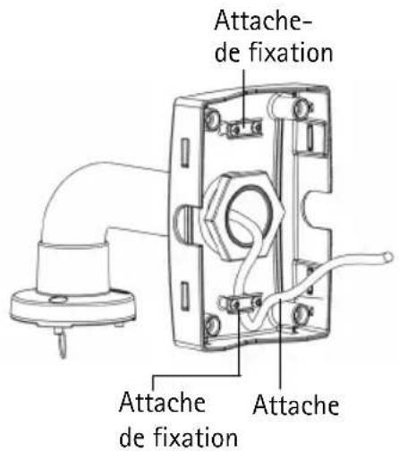
AXIS T91A Mounting Accessories
natural_image
3D rendering of a pipe fitting with mounting flanges (no text or symbols)Installieren der AXIS T91A62 Parapet Mount
natural_image
White U-shaped pipe fitting with a flanged base (no text or symbols visible)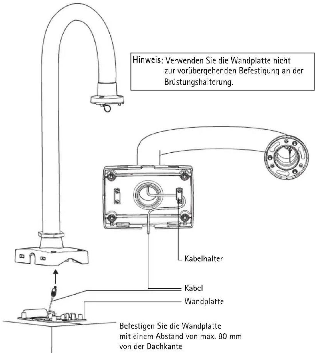
natural_image
Pure white cylindrical mechanical component with mounting holes and base (no text or symbols)natural_image
Technical line drawing of a mechanical assembly with a flanged shaft and internal components (no text or symbols)natural_image
Pure diagram of a pipe fitting with mounting bracket and side connectors (no text or symbols)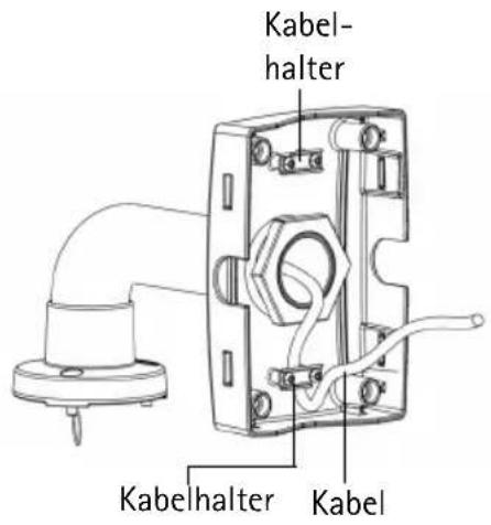
natural_image
3D rendering of a white pipe fitting with mounting flange (no text or symbols)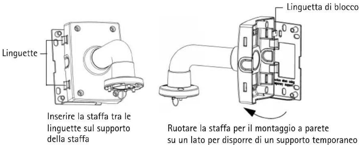
natural_image
White cylindrical pipe fitting with a flanged end, mounted on a base (no text or symbols visible)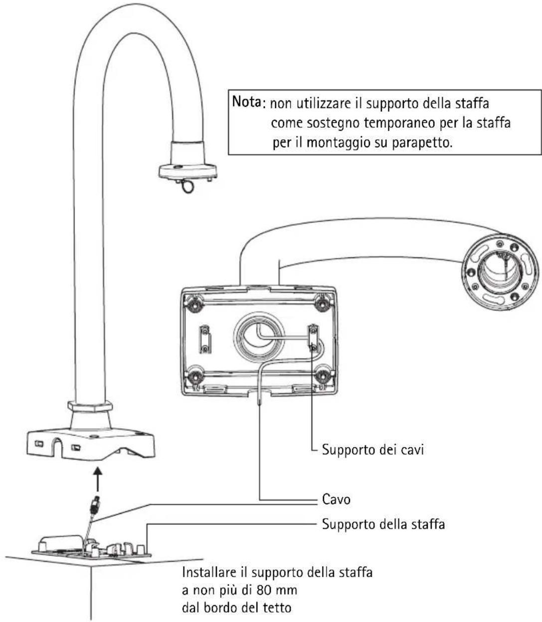
natural_image
Pure white cylindrical mechanical component with mounting holes and base (no text or symbols)natural_image
Technical line drawing of a mechanical assembly with a flanged shaft and internal components (no text or symbols)natural_image
3D rendering of a white industrial pipe fitting with mounting bracket (no text or symbols visible)Nota:
natural_image
Pure diagram of a pipe fitting with no text, numbers, or symbols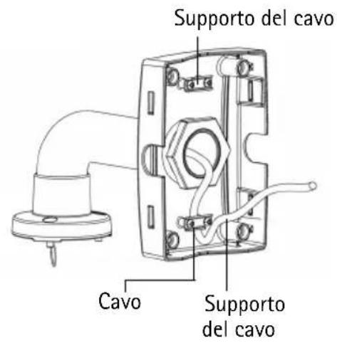
natural_image
3D rendering of a white pipe fitting with mounting flanges (no text or symbols)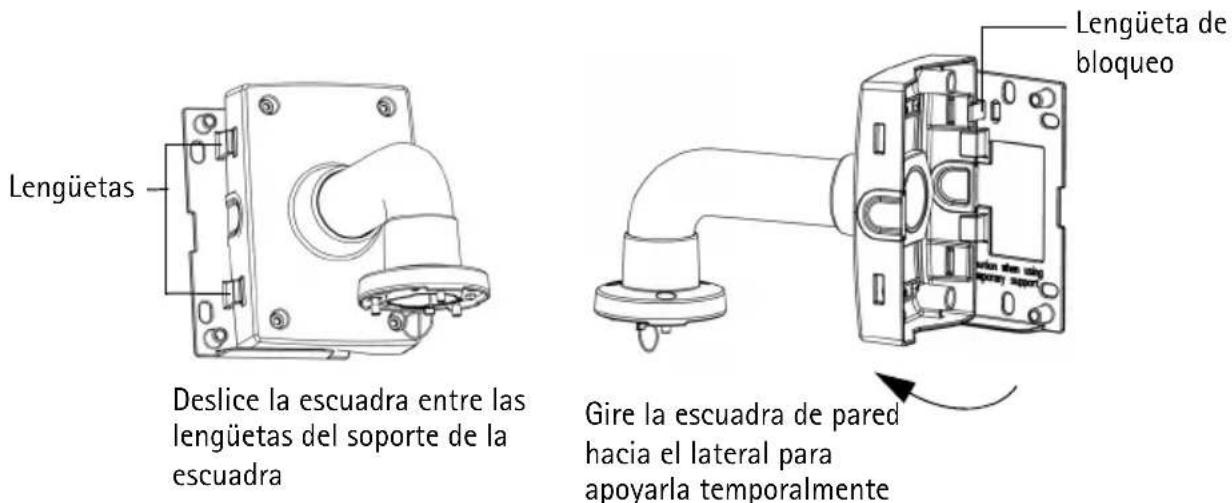
natural_image
White cylindrical pipe with a flanged end and base, no text or symbols visible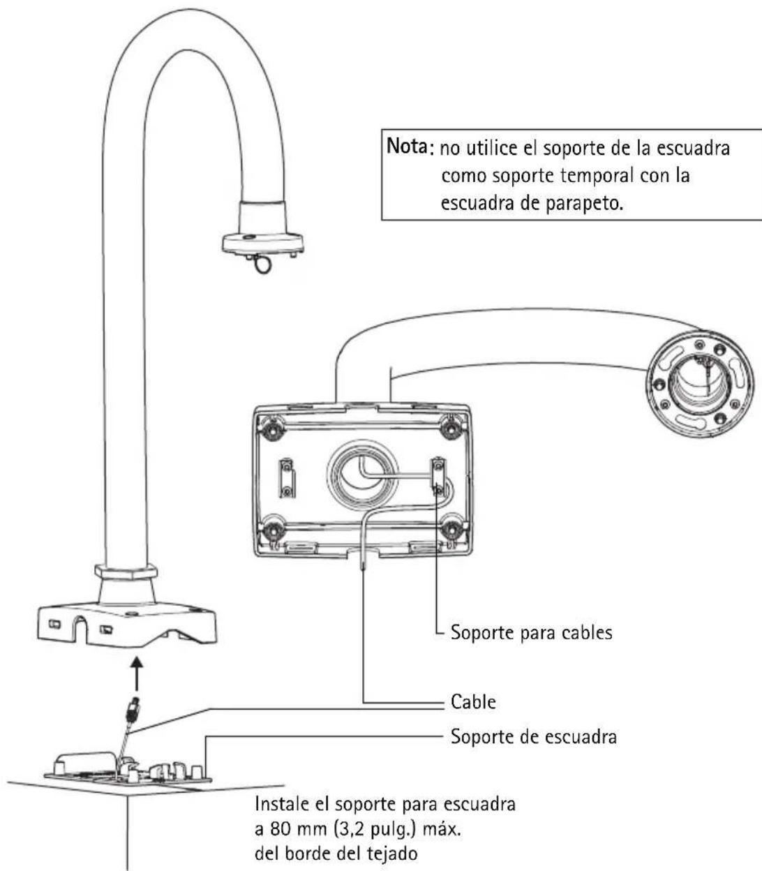
natural_image
Pure white cylindrical mechanical component with mounting holes, no text or symbols visiblenatural_image
Technical line drawing of a mechanical assembly with a cylindrical component and internal wiring (no text or symbols)natural_image
3D rendering of a white industrial pipe fitting with mounting bracket (no text or symbols)Nota:
natural_image
Technical line drawing of an electrical enclosure with pipe connection (no text or symbols)CableSoporte para
natural_image
Pure diagram of a pipe fitting with mounting brackets and a valve, no text or symbols present
© Axis Communications AB, 2009
Ver.1.00
Printed: December 2009
Part No. 37324
- About this Document
- Equipment Modifications
- Liability
- Support
- AXIS T91A Mounting Accessories
- Installation steps
- Important!
- Package contents
- ② Hardware overview
- Install the Hardware
- Install the AXIS T91A61 Wall Mount
- Install the AXIS T91A62 Parapet Mount
- Notes:
- Install the AXIS T91A63 Ceiling Mount
- Install the AXIS T91A64 Corner Mount
- Note:
- Install the AXIS T91A67 Pole Mount
- Installieren der AXIS T91A62 Parapet Mount
- Nota:
Brand : AXIS
Model : T91A64
Category : Mounting bracket