
LDSTND002 - Flat screen mount VIEWSONIC - Free user manual and instructions
Find the device manual for free LDSTND002 VIEWSONIC in PDF.
| Product type | Mobile flat screen stand (floor base) |
| Brand | Viewsonic |
| Model | LDSTND002 |
| Compatibility | ViewSonic Direct View LD163-181 only |
| Material | Steel |
| Casters | Yes, swivel with brakes |
| Color | Black |
| Package contents | Left and right brackets, lower and upper crossbars, M6x80mm bolts, M6x10mm screws and KM3x6mm screws, Allen key |
| Main functions | Floor stand for LED screen, allows installation of control boxes and LED modules |
| Maximum load capacity | Up to 200 kg (estimate for LD163-181 screen) |
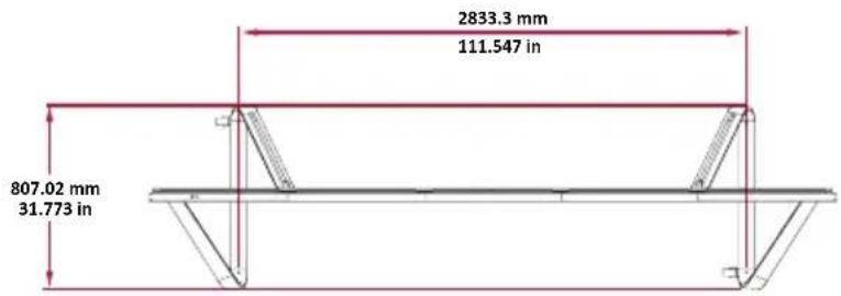
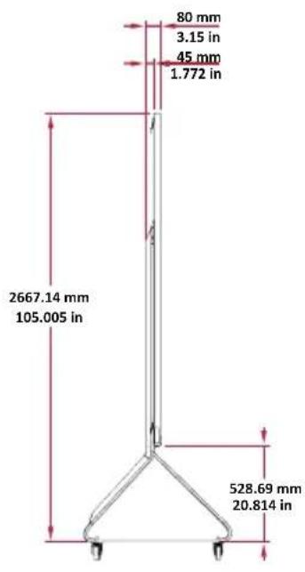
| Total height | Approximately 180 cm (estimate) |
| Total width | Approximately 150 cm (estimate) |
| Total depth | Approximately 80 cm (estimate) |
| Weight of stand alone | Approximately 50 kg (estimate) |
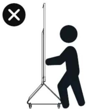
| Safety | Risk of tipping, do not push from the front, unlock wheels before moving |
| Maintenance | Clean with a soft dry cloth, do not use abrasive products |
| Repairability | Disassemble with tools (Allen key, screwdriver) |
| Warranty | 2 years (ViewSonic standard) |
| Installation | Requires assembly, follow the instructions in the manual |
Frequently Asked Questions - LDSTND002 VIEWSONIC
User questions about LDSTND002 VIEWSONIC
0 question about this device. Answer the ones you know or ask your own.
Ask a new question about this device
Download the instructions for your Flat screen mount in PDF format for free! Find your manual LDSTND002 - VIEWSONIC and take your electronic device back in hand. On this page are published all the documents necessary for the use of your device. LDSTND002 by VIEWSONIC.
USER MANUAL LDSTND002 VIEWSONIC
Floor Stand (LD-STND-002)
Compatible with LD163-181
All-in-one Direct View LED Display
Quick Start Guide
快速安装说明
快速入門指南
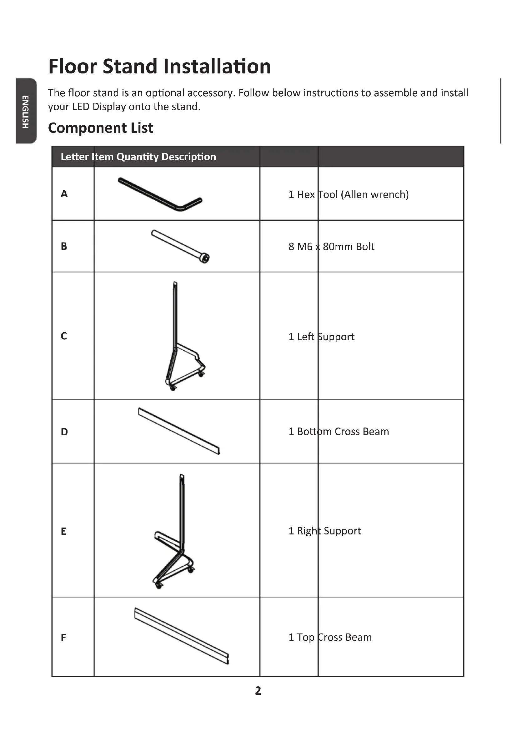
The floor stand is an optional accessory. Follow below instructions to assemble and install your LED Display onto the stand.
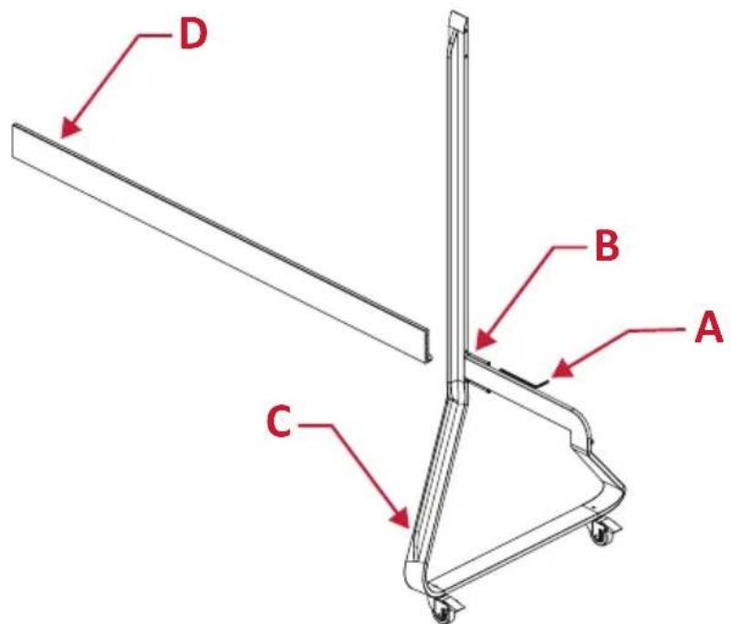
Component List
| Letter Item Quantity Description | |||
| A | 1 Hex | Tool (Allen wrench) | |
| B | 8 M6 x 80mm Bolt | ||
| C | 1 Left | Support | |
| D | 1 Bottom Cross Beam | ||
| E | 1 Right | Support | |
| F | 1 Top | Cross Beam | |

CAUTION
- This Stand is to be used with ViewSonic Direct View LD163-181 only. Using this stand with other models may cause instability and injury.
TIPPING HAZARD!
- DO NOT roll the stand over cable, uneven, dirty, soft, or high incline surfaces.
- DO NOT push the front of the display. Always unlock the wheels before moving. Failure to comply with this caution may result in equipment damage and personal injury.

Assembling the Floor Stand
- Connect the Left Support "C" to the Bottom Cross Beam "D" with two (2) M6 x 80mm bolts "B" and using an Allen wrench "A".
- Connect the Right Support "E" with the Bottom Cross Beam with two (2) M6 x 80mm bolts.
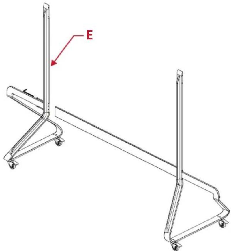
- Connect the Top Cross Beam "F" to the Left and Right Supports with four (4) M6 x 80mm bolts.

- Ensure all bolts are tightened properly with an Allen wrench.

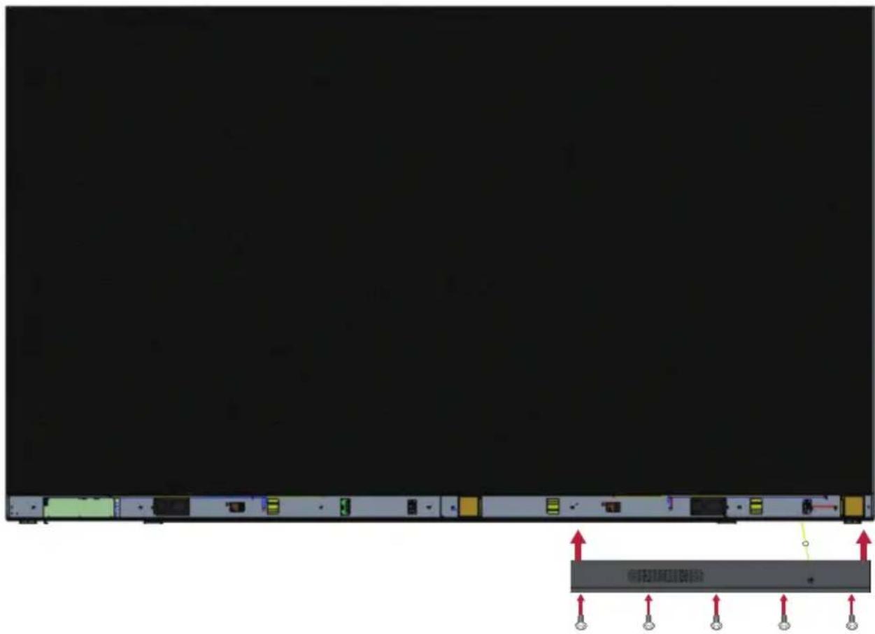
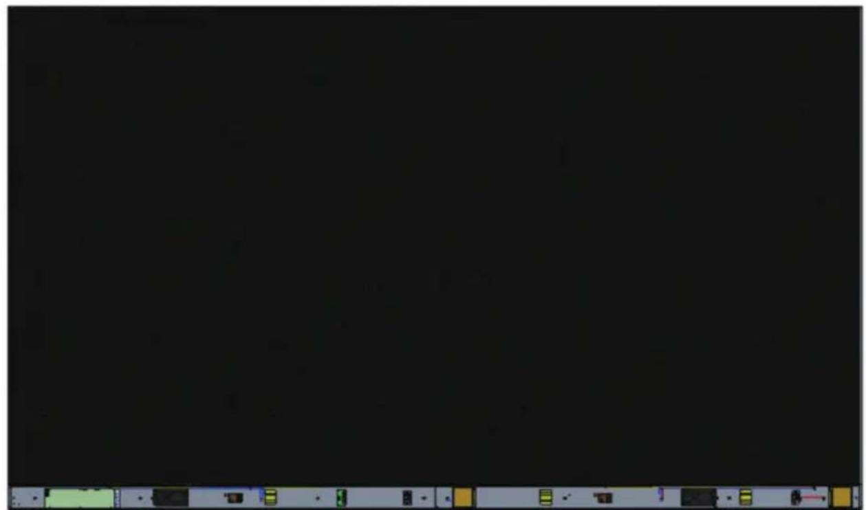
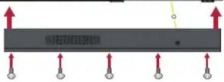
Connecting the System Control Box to the Floor Base
- Carefully unfold the System Control Box panel. Ensure the main system control board is on the left.
NOTE: Use caution as the System Control Box panel is separated into two pieces with wires attached.
- Align the System Control Box to the eight (8) holes on the Bottom Cross Beam and secure it with eight (8) M6x10mm screws.
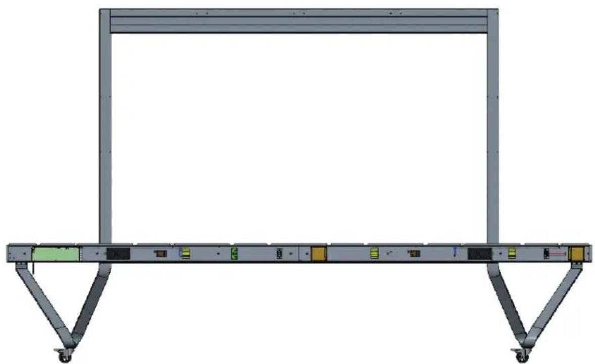
- Install two (2) additional screws (M6x10mm) to connect the two halves of the System Control Box.

NOTE: Screws (M6x10mm) are placed in the accessory box of the LED Display.
Installing the Middle Cabinets
- Ensure the four (4) Mounting Brackets on the rear of the four (4) Middle Cabinets are positioned as shown below:
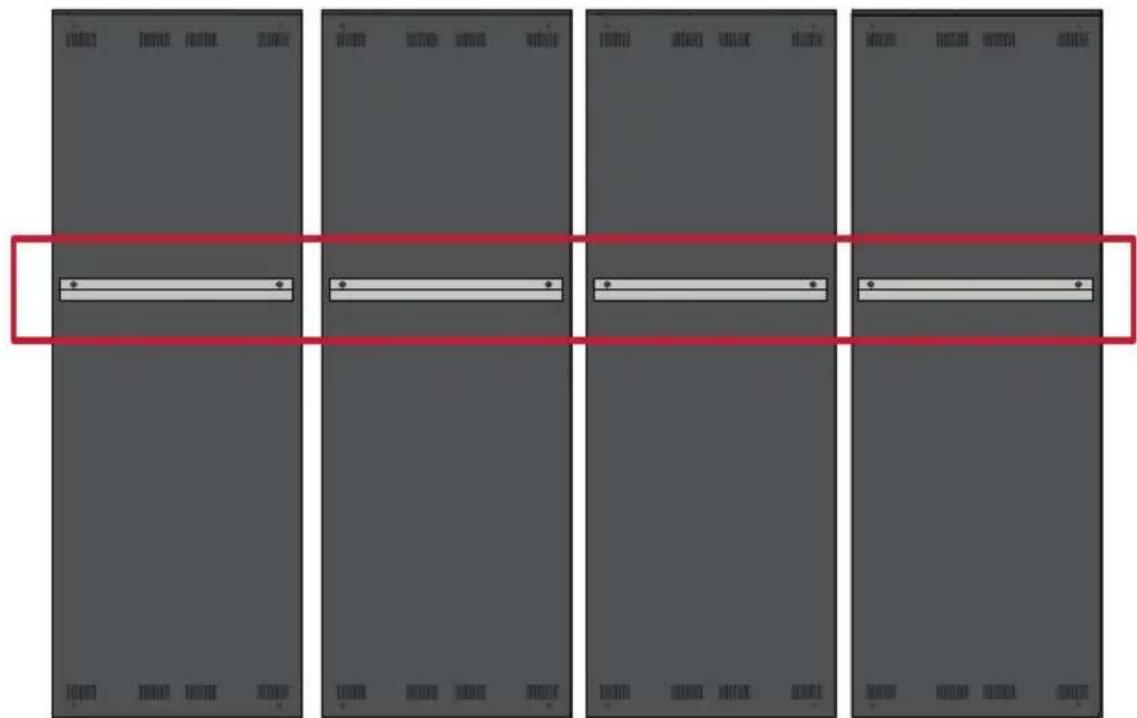
- Carefully lift a Cabinet up onto the Floor Stand, securing the Mounting Bracket into the support channel of the Top Cross Beam. The bottom of the Cabinet will rest on the Bottom Cross Beam.

- Secure the Cabinet to the Support with the provided screws (M6x10mm).

- Push each Locking Bolt and lock each Hook with the hex tool to securely connect each cabinet together. It may be necessary to align the hole with an Allen wrench in order to engage the Locking Bolt.

NOTE: There are six (6) Locking Bolts and 12 Hooks between each cabinet.
- Repeat Steps 2 4 for the remaining Middle Cabinets, Secure the Cabinet to the Right Support with the provided screws (M6x10mm).

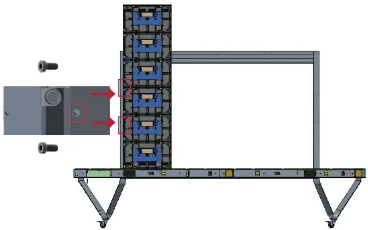
Installing the Left and Right Cabinet
- Carefully lift the Left and Right Cabinet up onto the Floor Stand, securing the Mounting Bracket into the support channel of the Top Cross Beam. The bottom of the Cabinet will rest on the Bottom Cross Beam.
NOTE: Ensure the holes of the Cabinet and the System Control Box are aligned.
- Push each Locking Bolt and lock each Hook with the hex tool to securely connect the Left and Right Cabinet to the Middle Cabinets.
- Secure the Left and Right Cabinet to the Support with the provided screws (M6x-10mm).

NOTE: There are six (6) Locking Bolts and 12 Hooks between each cabinet.
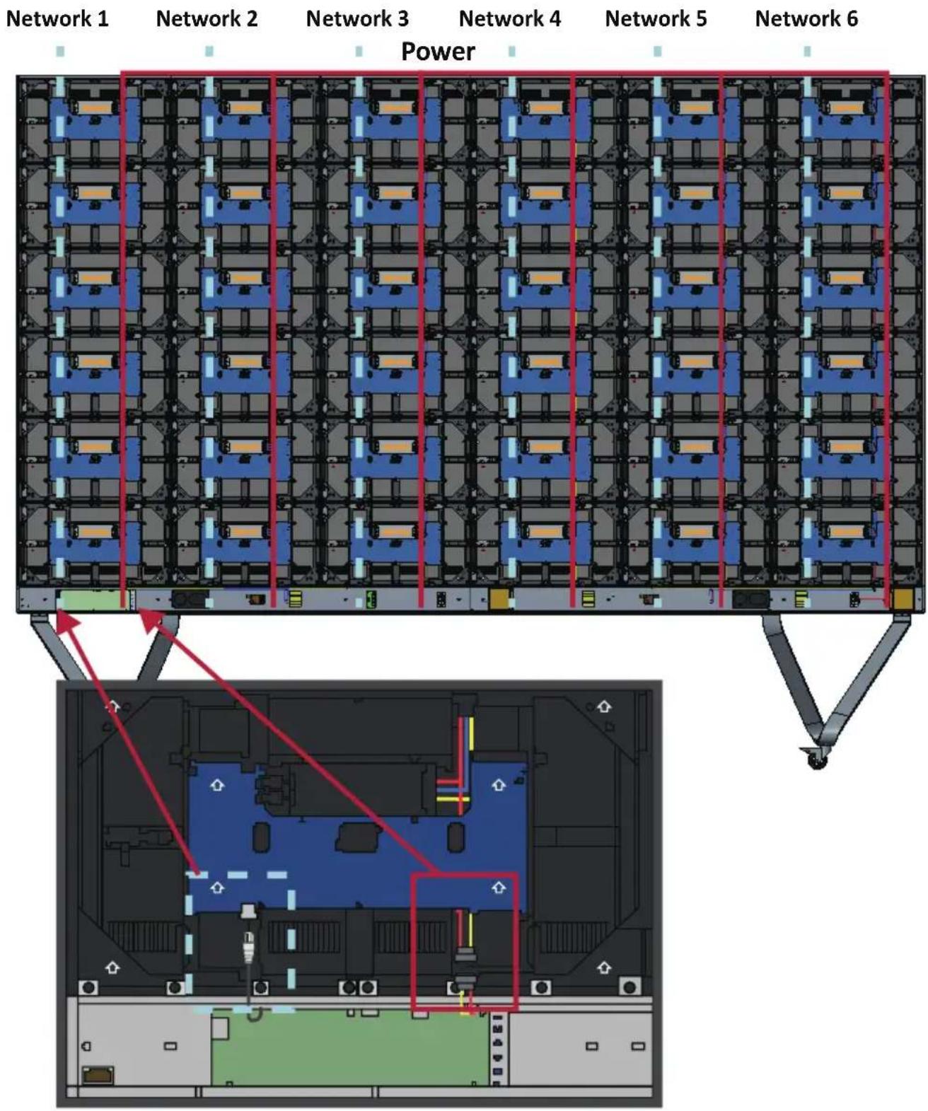
Connect the Network and Power Cables
Connect the Network and Power cables of each Cabinet to the System Control Box.
NOTE: There are six (6) Network and six (6) Power cables to connect.
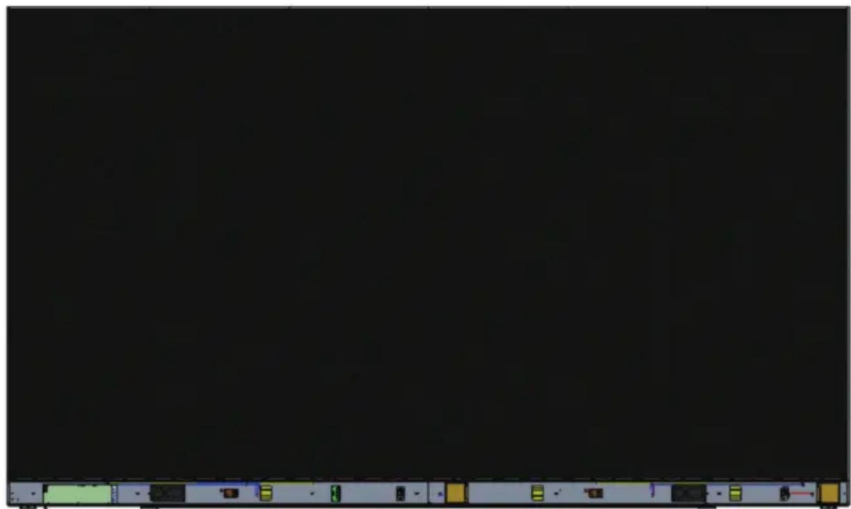
Installing the LED Modules
Install each LED Module onto the Cabinets, being sure to match the corresponding numbers on the Module to the Cabinet. Ensure each Module is flush and that there is little to no gap between each. It may be necessary to gently tap the module to make it flush.
CAUTION Please wear Anti-Static Gloves before handling the LED modules.
Installing System Control Box Covers
There are three (3) System Control Box Covers: Left, Middle, and Right.


- Begin by installing the Right Cover onto the System Control Box.
NOTE: Ensure the Power Button cable is connected to the System Control Box Power cable before securing the Cover.
- After connecting the Power Button cable, ensure the Right Cover is properly aligned with the System Control Box; then secure it with the 15 provided screws (KM3x6mm).
NOTE: Screws (KM3x6mm) are placed in the accessory box of the LED Display.

- Repeat the above steps for the Middle and Left Cover. Once all of the Covers are secured, your LED Display is ready to power on.

落地支架安装
YcTaHOBka CBeToaNoJNbIX MoyJeN
YCTAHOBITE KaJdbi CBeToDnOHDhIM MOyIb B KOpNyc, y6eINBWHscb, YTO COOTBeTCTByUoIe HOMepa, yKa3aHHbIe Ha MoIyIe, COBnaJaOT co Homepom ShkaΦa. Y6eHITecb, YTO KaJdbi MOyIb YCTAHOBJIeH BPOBeHc DpyrHMn I MeKdY HmMn Het 3a30pa. Bo3MOxHIO, Notpe6yeTcR octopoxHO nocTyatb NO MOyIIO, YTO6bl BBipOBHraTb erO.

BHIMAHNE! IopkaIyIcTa,HaJeHbTe aHTncTaTnueckne nepaATkn nepei pa60ToC o CBeToIDNoIDhBIMN MOdYlAmN.

YcTaHOBKa KpbIweK CnCTeMHoN KOPO6Kn YnpaBHeHna
IMeetc3 (tpn) KpbIshKc nCTeMHoN KOPO6Kn ynpaBHeHna: JeBa, CpeHra n IpaBaJ.

- Hauhnte c yctaHOBKn npaBov KpbIshKn CnCTeMHoN KOPO6Kn ynpaBHeHna.
ПРИМЕЧАН. Перд зakpenlenem Крblшкубentecь,чTo Ka6eJIb KhoNKn NITaHЯ NOdkIIOUeH K Ka6eJIIO NITaHЯ сnteMHOJ Kopo6Kn ynpabLeHЯ.
- Посл подкюець кабел Кноги ппань убетсь,чTo npabay Кршka npablnbHo coBmeцeha c cnctemHoi kopo6koyn ynpabIeHn; 3aTeM 3akpenite ee c nomoць10 priIaraeMbIX 6oITOB (KM3x6 MM).
- FLOOR STAND (LD-STND-002)
- CAUTION
- TIPPING HAZARD
- ASSEMBLING THE FLOOR STAND
- CONNECTING THE SYSTEM CONTROL BOX TO THE FLOOR BASE
- INSTALLING THE MIDDLE CABINETS
- INSTALLING THE LEFT AND RIGHT CABINET
- CONNECT THE NETWORK AND POWER CABLES
- INSTALLING THE LED MODULES
- INSTALLING SYSTEM CONTROL BOX COVERS
- 落地支架安装
- YCTAHOBKA CBETOANOJNBIX MOYJEN
- YCTAHOBKA KPBIWEK CNCTEMHON KOPO6KN YNPABHEHNA
Brand : VIEWSONIC
Model : LDSTND002
Category : Flat screen mount