
S3M100KXD - Inverter Tripp Lite - Free user manual and instructions
Find the device manual for free S3M100KXD Tripp Lite in PDF.
| Product Type | Three-phase double-conversion online UPS |
| Brand | Tripp Lite |
| Model | S3M100KXD |
| Capacity | 100 kVA / 90 kW |
| Nominal Input Voltage | 380/400/415 V three-phase + neutral (Ph-Ph), 220/230/240 V (Ph-N) |
| Input Voltage Range | 305-478 V Ph-Ph (load >80%) |
| Input Frequency | 50/60 Hz (auto-sensing), range 40-70 Hz |
| Nominal Output Voltage | 380/400/415 V three-phase + neutral (Ph-Ph), 220/230/240 V (Ph-N) |
| Output Voltage Regulation | ±1% (balanced load, double conversion mode) |
| Output Power Factor | 0.9 |
| Battery Type | External, sealed VRLA AGM/GEL 12 V, 40 cells (series 20+20) |
| Runtime | Varies by external battery cabinet (5 min to 3 h at 100% load) |
| Dimensions (H x W x D) | 1015 x 567 x 945 mm |
| Weight (without batteries) | 197 kg |
| Operating Modes | Line, Battery, Bypass, ECO, Converter, Standby, Shutdown |
| Line mode efficiency | 94% at 100% resistive load |
| ECO mode efficiency | 98% at 100% resistive load |
| Communication | RS-232, USB, SNMP slot (WEBCARDLX), dry contact (RELAYCARDSV) |
| Protection | Network monitoring, remote emergency power off (REPO), paralleling up to 2 units |
| Safety Standards | IEC 62040-1:2008+A1:2013 (TÜV certified) |
| EMC Compliance | EN 62040-2:2006 Category C3 |
| Operating Temperature | 0 to 40 °C (25 °C optimal for battery) |
| Included Accessories | Manual, RS-232 cable, door key, parallel cable (P100200KIT) |
| Maintenance | Batteries and fans replaceable by qualified personnel |
Frequently Asked Questions - S3M100KXD Tripp Lite
User questions about S3M100KXD Tripp Lite
0 question about this device. Answer the ones you know or ask your own.
Ask a new question about this device
Download the instructions for your Inverter in PDF format for free! Find your manual S3M100KXD - Tripp Lite and take your electronic device back in hand. On this page are published all the documents necessary for the use of your device. S3M100KXD by Tripp Lite.
USER MANUAL S3M100KXD Tripp Lite
Models: S3M100KX, S3M100KXD, S3M120KX, S3M120KXD, S3M160KX, S3M160KXD, S3M200KX, S3M200KXD
Input: 220/230/240V (Ph-N), 380/400/415V (Ph-Ph), 3Ø 4-Wire + PE


Table of Contents
1. Introduction 3
2. Important SafetyWarnings 4
2.1 UPS Location Warnings 4
2.2 Equipment Connection Warnings 4
2.3 BatteryWarnings 4
2.4 Transportation and Storage 5
2.5 Preparation 5
2.6 Installation 5
2.7 ConnectionWarnings 5
2.8 Operation 6
2.9 Standards 6
3. Installation and Setup 7
3.1.Unpacking and Inspection 7
3.2.Open Front Panel View 9
3.2.1 Interface and Communication 10
3.2.2 Power Stage/Module 10
3.3 Rear Panel View 11
3.4 Wiring Terminal Views 12
3.5 Single UPS Installation 13
3.6UPS Installation for Parallel Systems 15
3.6.1 Input and Output Wiring 15
3.6.2 Parallel Board Setting 17
3.6.3 Parallel Function Setting 19
3.6.4 Parallel Cable Connection 19
3.6.5 Parallel System Turn On Procedure 20
3.7 Dual AC Input Installation 20
4. Control Panel and LCD Operation 21
4.1 Control Panel Description 21
4.2 LCD Screen Description 22
4.2.1 Initial Screen 22
4.2.2 Main Screen 22
4.2.3 Control Screen 23
4.2.4 Measurement Screen 24
4.2.5 Setup Screen 26
4.2.6 Information Screen 37
4.2.7 Event Screen 38
4.3 Alarm List 40
4.4 History Record 41
5. Interface and Communication 42
5.1 X1-Temperature Detection Port for 42 External Battery Pack
5.2 X2 - Remote EPO Input Port 43
5.3 Other Communication Interfaces 43
6. Operation Principles 44
6.1UPS Block Diagram 44
6.2Operation Modes 45
6.2.1 Standby Mode 45
6.2.2 Line Mode 46
6.2.3 Battery Mode 47
6.2.4 Frequency Conversion Mode 48
6.2.5 Bypass Mode 49
6.2.6 ECO Mode 50
6.2.7 Shutdown Mode 51
6.2.8 Maintenance Bypass Mode 52
7. UPS Operation 53
7.1 AC Startup 53
7.2 Cold Start Startup 55
7.3 Maintenance Bypass Operation 57
7.3.1 Transfer Critical Load from Line Mode to 57 Maintenance Bypass
7.3.2 Transfer Critical Load from 59 Maintenance Bypass to Line Mode
7.4 Turn Off Operation 61
7.4.1 Turn Off Operation in Line Mode 61
7.4.2 Turn Off Operation in Battery Mode 62
8.Troubleshooting 64
9.Storage and Service 66
9.1 Storage 66
9.2 Service 66
9.3 Batteries 66
9.4 Fans 66
10. Specifications 67
Warranty 70
Espanol 71
Français 142
Pycckn 212
Deutsch 283
1. Introduction
Tripp Lite's SmartOnline S3MX-Series Uninterruptible Power Supply (UPS) is a Voltage and Frequency Independent (VFI) true on-line, double-conversion 3-phase UPS system. This UPS continuously conditions the incoming electrical power supply, eliminating power disturbances that will otherwise damage sensitive electronic devices and minimising system downtime from power fluctuations and interruptions.
S3MX-Series UPS systems are designed to the highest quality and performance standards and offer the following features:
| Model Agency Number Capacity | |
| S3M100KX, S3M100KXD* AG-6100 100kVA | |
| S3M120KX, S3M120KXD* AG-6120 120kVA | |
| S3M160KX, S3M160KXD* AG-6160 160kVA | |
| S3M200KX, S3M200KXD* AG-6200 200kVA |
- "KXD" models are dual-AC input capable.
True on-line UPS - the highest level of UPS protection, fully regulates the incoming power with zero transfer time to battery in the event of an extended mains failure, so critical loads remain continuously supported - Paralleling for redundancy and capacity for up to two UPS systems
- High-efficiency performance in AC On-line and Battery Standby Modes to minimise energy consumption
Market-leading small size and footprint - ECO Mode allows the UPS to operate on bypass in stable utility conditions and immediately transfers to inverter to support the load when the utility input drops below tolerance
- High output power factor - more actual power allows more equipment to be supported
Automatic and manual bypass increase system reliability and allow for maintenance without removing power from the attached load - Wide input voltage window - the UPS system regulates even poor-quality incoming power without reverting to battery, maximising system uptime and protecting battery life
- Matching external battery cabinets allow for increased battery autonomy
Emergency shutdown via REPO
SNMP Network Monitoring and volt-free contact options provide optimum configurability - Optional dual-AC input "KXD" models available
SmartOnline S3MX-Series UPS systems are ideally suited for protecting 4-wire loads in the following mission-critical electrical applications:
IT infrastructure and data centres
Telecommunications
Networks (LAN/WAN)
Corporate infrastructure
- Security and emergency systems
Financial institutions
Healthcare and hospitals
2. Important SafetyWarnings
SAVE THESE INSTRUCTIONS
This manual contains important instructions and warnings that should be followed during the installation and maintenance of all Tripp Lite SmartOnline S3MX 3-Phase 100kVA, 120kVA, 160kVA and 200kVA UPS Systems and their batteries. Failure to heed these warnings may affect your warranty.
2.1 UPS LocationWarnings
Install the UPS indoors, away from heat, direct sunlight, dust, and excess moisture or other conductive contaminants.
- Install the UPS in a structurally sound area. The UPS is extremely heavy; take care when moving and lifting the unit.
- Only operate the UPS at indoor temperatures between 0^ and 40^ .
Optimum UPS performance and maximum battery life is obtained when the operating temperature is maintained between 17^ and 25^ .
- Ensure the installation area has sufficient space for maintenance and ventilation of the UPS system. Maintain a minimum clearance of 50~cm from the front and rear of the UPS for maintenance and ventilation.
- Do not install the UPS near magnetic storage media, as this may result in data corruption.
2.2 Equipment ConnectionWarnings
- Use of this equipment in life support applications where failure of this equipment can reasonably be expected to cause the failure of the life support equipment or to significantly affect its safety or effectiveness is not recommended.
- The UPS system contains its own energy source (battery). The output terminals may be live, even when the UPS is not connected to an AC supply.
The UPS models covered in this manual are not compatible with loads that do not have a Neutral Reference or Delta load.
2.3 BatteryWarnings
This UPS contains LETHAL VOLTAGES. The UPS is designed to supply power, even when disconnected from utility power. Only AUTHORISED SERVICE PERSONNEL should access the interior of the UPS after disconnecting utility and DC power.
Batteries present a risk of electrical shock and burns from high short-circuit current. Battery connection or replacement should be performed by only qualified service personnel observing proper precautions. Turn off the UPS before connecting or disconnecting internal batteries. Use tools with insulated handles. Do not open the batteries. Do not short or bridge the battery terminals with any object.
The batteries are recyclable. Refer to local codes for disposal requirements or visit triplite.com/support/recycling-program for recycling information.
- Do not dispose of the batteries in a fire, mutilate the batteries or open the battery coverings. Escaping electrolytes may be toxic and cause injury to skin and eyes.
- Do not disconnect the batteries while the UPS is in Battery Mode.
- Disconnect the charging source prior to connecting or disconnecting terminals.
The following precautions should be observed:
1) Remove watches, rings and other metal objects.
2) Use tools with insulated handles.
3) Wear rubber gloves and boots.
4) Do not lay tools or metal parts on top of batteries or battery cabinets.
5) Determine whether the battery supply (+, -, N) is inadvertently grounded. If it is, remove the source of the ground. Contact with any part of a grounded battery can result in electric shock. The likelihood of an electric shock is reduced if such grounds are removed during installation and maintenance.
- Battery replacement should be performed only by authorised service personnel, using the same number and type of batteries (sealed lead acid).

WARNING: In order to avoid any hazardous conditions during UPS installation and maintenance, these tasks may be performed only by qualified and experienced electricians.
Please read this Owner's Manual and safety instructions carefully before installing or using the unit.
2. Important SafetyWarnings
2.4 Transportation and Storage
To protect against shock and impact, transport the UPS system using only its original packaging.
The UPS must be stored in a room that is dry and ventilated.
2.5 Preparation
Condensation may occur if the UPS system is moved directly from a cold to warm environment. The UPS system must be completely dry before being installed. Please allow at least two hours for the UPS system to adjust to the environment.
Do not install the UPS system near water or in moist environments.
Do not install the UPS system in direct sunlight or near heat sources.
Do not block the ventilation holes on the UPS system's housing.
2.6 Installation
Do not connect appliances or devices that could overload the UPS (i.e., equipment with large electrical motors) to the UPS output sockets or terminal.
Carefully arrange cables so no one can step on or trip over them.
Do not block the UPS system's air vents. The UPS must be installed in a location with good ventilation. Ensure adequate ventilation space on each side of the unit.
The UPS contains an earthed terminal. In the final installed system configuration, ensure equipotential earth grounding to the external UPS battery cabinet by connecting the earth terminals of both cabinets together.
The UPS should only be installed by qualified service personnel.
An appropriate disconnect device such as short-circuit backup protection must be provided in the building wiring installation.
An integral single-emergency switching device should be included in the building wiring installation.
Connect the earth ground before connecting to the building wiring terminal.
Installation and wiring must be performed in accordance with local electrical codes and regulations.
2.7 ConnectionWarnings
- The UPS system does not contain standard backfeed protection inside. Isolate the UPS before working on this circuit. The isolation device must be able to carry the UPS input current.
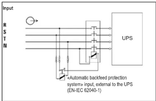
- This UPS should be connected with TN earthing system.
- The power supply for this unit must be 3-phase rated in accordance with the equipment nameplate. It also must be suitably grounded.
- The input power to 3-phase UPS models require a 3-pole breaker.
- Use of this equipment in life support applications where failure of this equipment can reasonably be expected to cause the failure of the life support equipment or to significantly affect its safety or effectiveness is not recommended.
- Connect the UPS power module's grounding terminal to a grounding electrode conductor.
- The UPS is connected to a DC energy source (battery). The output terminals may still be live, even when the UPS is not connected to an AC supply.
2. Important SafetyWarnings
- When installing the unit, verify that any maintenance bypass panel used is configured correctly before applying power to the unit.
- Be sure to place a warning label on all primary power isolators installed remotely from the UPS area and on any external access points between such isolators and the UPS. The warning label shall carry the following wording or equivalent.
Before working on this circuit
-
Isolate Uninterruptible Power System (UPS)
-
Then check for Hazardous Voltage between all terminals
including the protective earth.
Risk of Voltage Backfeed
2.8 Operation
Do not disconnect the earth conductor cable on the UPS or the building wiring terminals at any time, as this will cancel the protective earth of the UPS system.
In order to fully disconnect the UPS system, first press the "OFF" button, then disconnect the mains.
Ensure no liquid or other foreign objects can enter into the UPS system.
2.9 Standards
| *Safety | |
| IEC 62040-1: 2008+A1:2013 | |
| *EMI | |
| Conducted Emission......EN 62040-2: 2006 C category C3 | |
| Radiated Emission......EN 62040-2: 2006 C category C3 | |
| *EMS | |
| ESD......EN 61000-4-2 Level 4 | |
| RS......EN 61000-4-3 | Level 3 |
| EFT......EN 61000-4-4 | Level 4 |
| SURGE......EN 61000-4-5 | Level 4 |
| CS......EN 61000-4-6 | Level 3 |
| Power-Frequency Magnetic Field......EN 61000-4-8 Level 4 | |
| Low-Frequency Signals......EN 61000-2-2 | |
| Warning: This is a product for commercial applications. Installation restrictions or additional precautions may be needed to prevent disturbances. | |
3. Installation and Setup
3.1 Unpacking and Inspection
Unpack the unit and inspect its contents. Packaging may include additional accessories and components, depending on specific customer orders.
One (1) UPS
One (1) Owner's Manual
One (1) RS-232 Cable
One (1) paralleling cable for every set of UPS units being paralleled: P100200KIT
Other Accessory or Component Options Available Upon Request
One (1) Battery Charger Temperature Compensation Thermostat: TEMPC100200
Note: Do not turn on the unit. Make sure to inspect the unit prior to installation. Ensure nothing inside the package was damaged during transportation. Notify the carrier and dealer immediately if there is any damage or missing parts. Please keep the original packaging in a safe place for future use.
- Use a forklift to move the product to the installed area. Make sure the bearing capacity of forklift is sufficient. Refer to Figure 3.1.
- Follow the unpacking order in Figure 3.2 to remove carton (1, 2) and foams (3).
- Remove two fixing plates located on the two sides of the unit (1, 2 and 3) in Figure 3.3. Loosen leveling feet (4) by rotating them counterclockwise. Once loosened, move the cabinet from the pallet.
- To fix the cabinet into position, simply rotate leveling feet clockwise. Refer to Figure 3.4.
S3M100KX, S3M100KXD and S3M120KX, S3M120KXD Models
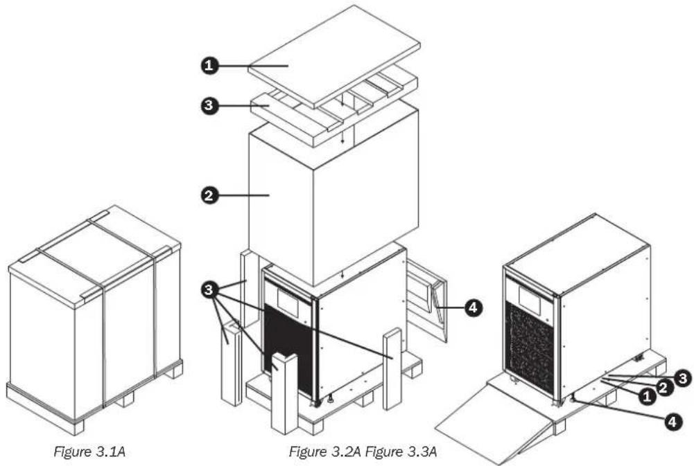
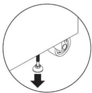
Figure 3.4A Figure 3.5A
3. Installation and Setup
S3M160KX, S3M160KXD, and S3M200KX, S3M200KXD Models
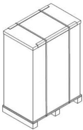
Figure 3.1B
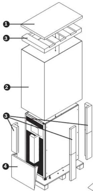

Figure 3.2B Figure 3.3B
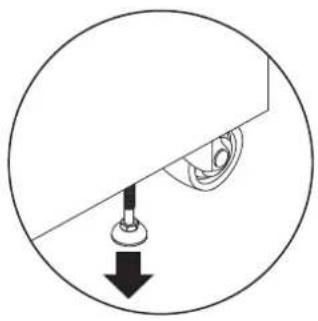
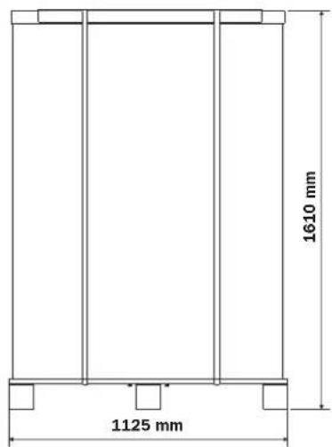

Figure 3.4B Figure 3.5B
3. Installation and Setup
Remove the accessory package and inspect the package contents. The standard shipping package should contain an Owner's Manual and RS-232 cable. The key to the UPS is attached to the front door with a cable tie. Packaging may also include additional accessories and components, depending on specific customer orders.
Note: Before installing, please inspect the unit. Ensure there is no physical damage to the unit. Do not turn on the unit. Notify the carrier and dealer immediately if there is any damage or missing parts and accessories. Keep the original packaging for future use. It is recommended you keep each equipment and battery set in their original packaging, as it is designed to provide maximum protection during transportation and storage.
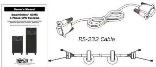
Owner's Manual
P100200KIT Paralleling Cable
3.2 Open Front Panel View
Each UPS comes equipped with a front door key. The key can be found attached to the front door with a cable tie. Upon opening the front door, you will see the communication area and several power stages/modules inside. From each power stage/module you can easily identify its ID.
Table 3.1 Power Stage ID
| Power Rating 100K 120K 160K 200K | ||||
| Stage ID-Individual Unit Operation | ||||
| Stage ID-For Parallel UPS | ||||
3. Installation and Setup
3.2.1 Interface and Communication
These UPS systems come equipped with various communication devices. Please refer to section 5. Interface and Communication for further details.
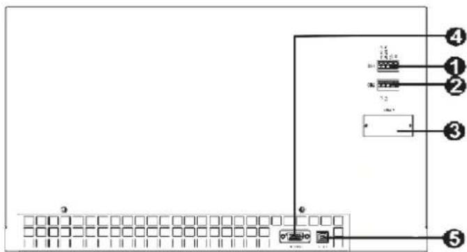
1 Dry Contact Port X1 (Optional battery temperature compensation thermostat)
2 Dry Contact Port X2 (EPO)
SNMP Slot (Optional WEBCARDLX or RELAYCARDSV card)
4 RS-232 Port
USB Port
3.2.2 Power Stage/Module
Each power stage/module includes a power factor correction rectifier, a battery charger, an inverter and control circuit.
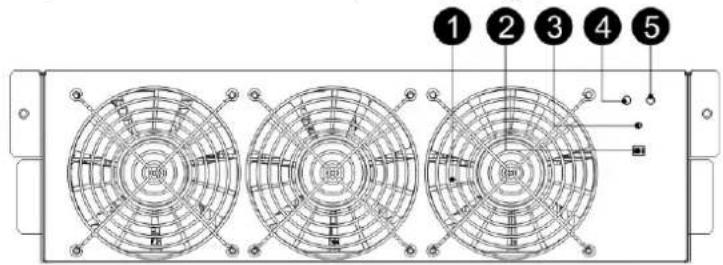
| No. Item Description | ||
| 1 | Fan | Air enters the power stage through the front grills and is exhausted through the rear of the module. Do not block the ventilation vent. |
| 2 | Stage Address DIP Switches | There are three DIP switches for Power Stage address setting. In the same cabinet, each Power Stage ID MUST be exclusive. Refer to Table 3.1 Power Stage ID for more information. |
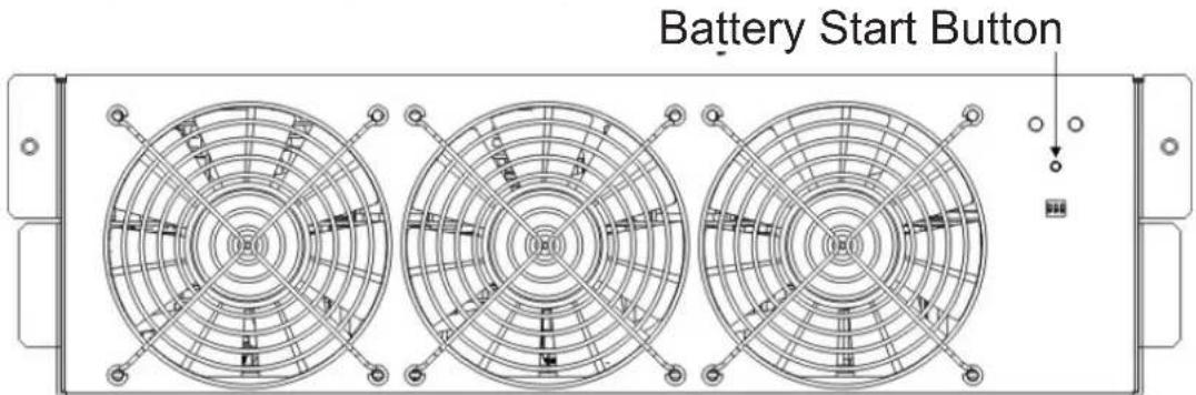
| 3 | Battery Start Button When AC input is not available, use this button to start UPS battery power. | |
| 4 | FAULT LED | ON The power stage is in fault condition. |
| ON/OFF 0.5 sec The power stage IDs are in conflict. | ||
| 5 | RUN LED | ON The power stage normally works as a secondary stage. |
| ON/OFF 0.5 sec The power stage normally works as a primary stage. | ||
| ON/OFF 0.15 sec The CAN Bus communication does not work. | ||
3. Installation and Setup
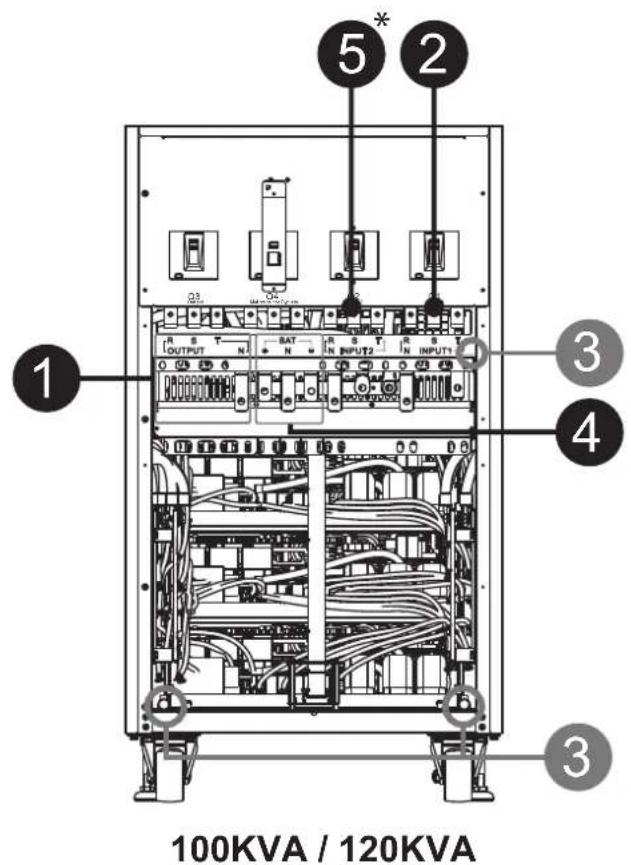
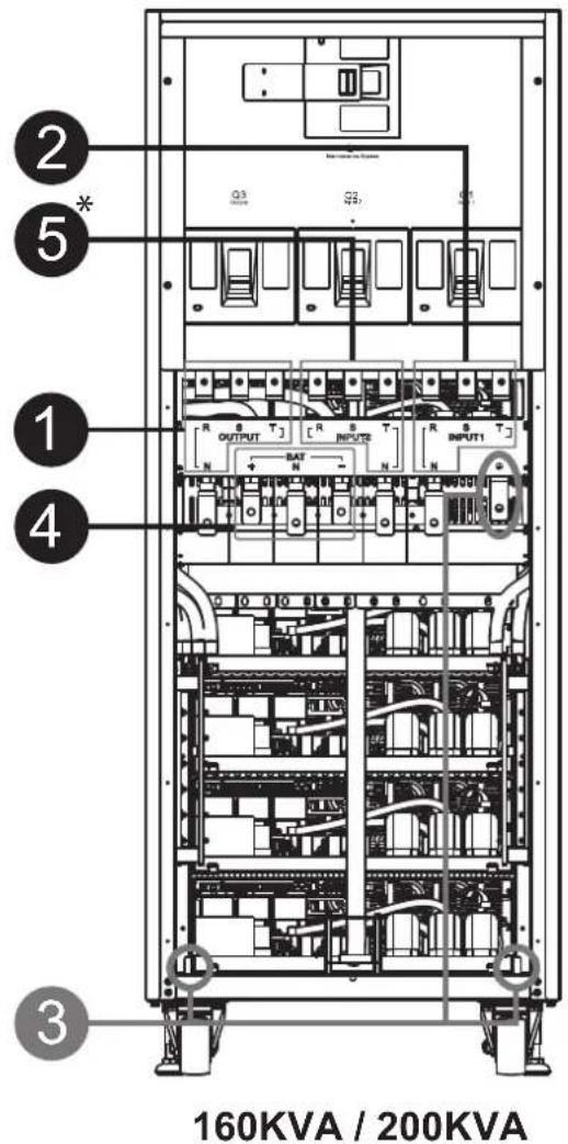
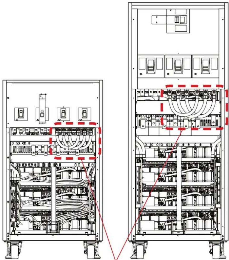
3.3 Rear Panel View
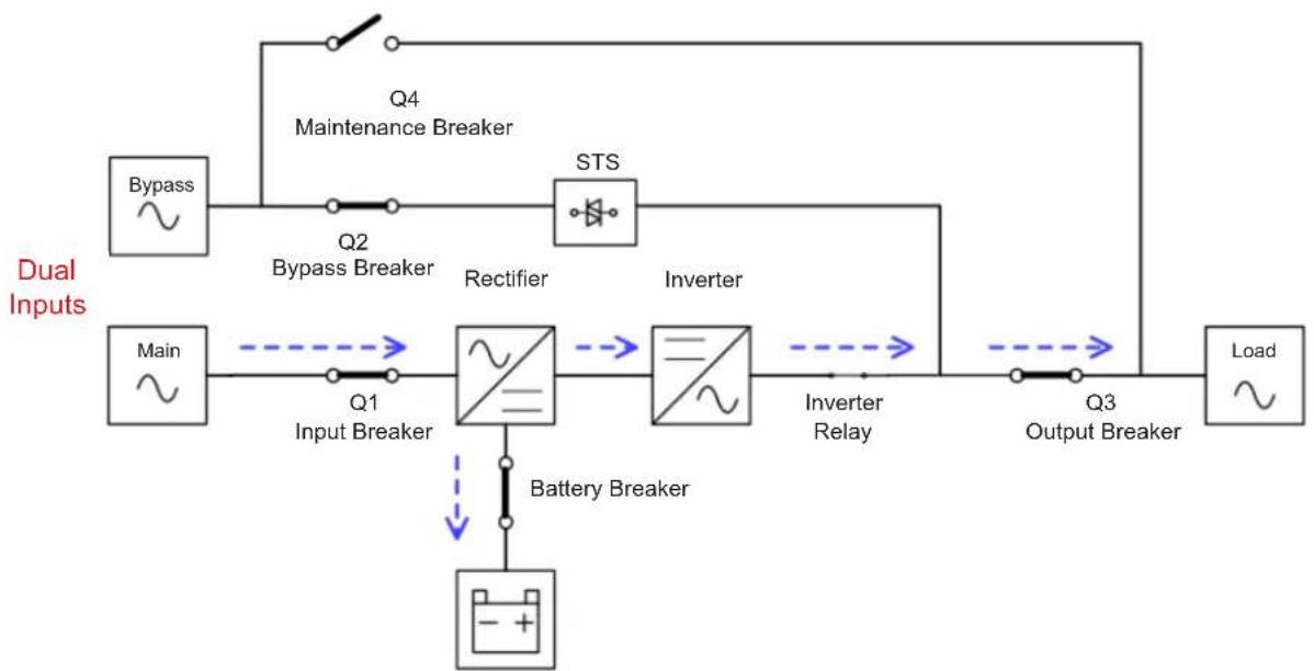
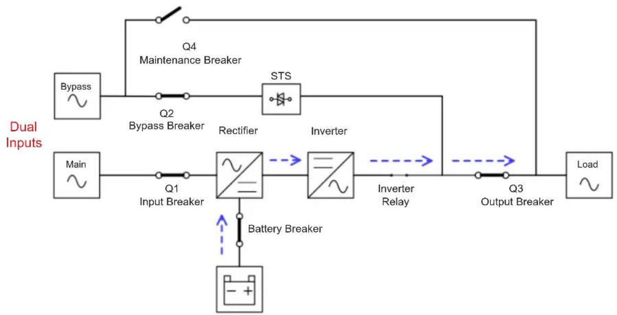
Several breakers are located on the rear panel of the UPS. Models with a second AC input (Q2) are also available. The breakers shown are Q1 input 1, Q2 input 2^* , Q3 output and Q4 maintenance bypass.
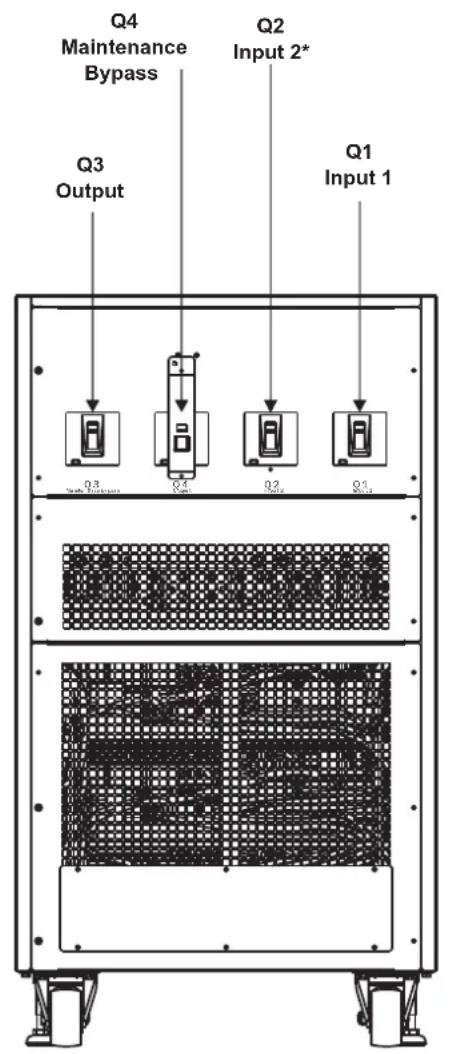
100KVA / 120KVA 160KVA / 200KVA
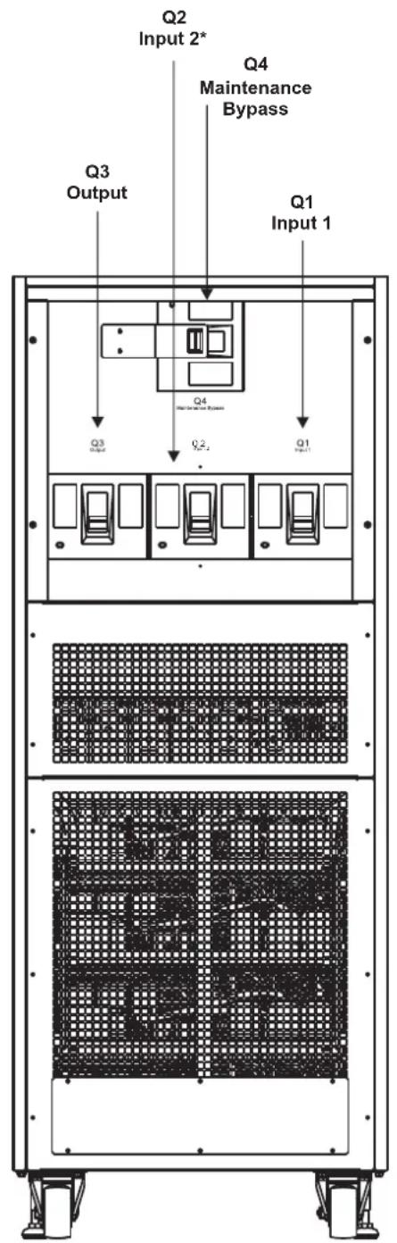
*Second AC circuit breaker (Q2) only applicable on second AC-input models with "KXD" suffix.
3. Installation and Setup
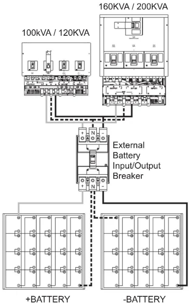
3.4 Wiring Terminal Views
| No. | Item Function Description | ||
| 1 | Output Block Connects to the critical loads Includes R, S, T and Neutral terminals. | ||
| 2 | Main Input Block Connects to main AC source Includes R, S, T and Neutral terminals. | ||
| 3 | Ground Connection For UPS grounding Includes one grounding terminal. | ||
| 4 | Battery Input Block Connects to an external battery cabinet | Includes: Positive (+), Negative (-) and Neutral (N) terminals. | |
| 5* | Second Input Block Connect to second AC source Includes R, S, T and Neutral terminals. |
*Second AC input block only applicable on second AC-input models with "KXD" suffix.
3. Installation and Setup
3.5 Single UPS Installation
Installation and wiring must conform with the local electric laws/regulations. The following procedures must be performed by a professional electrician:
1) Make sure the mains wire and breakers in the building provide adequate power for the rated UPS capacity so as to avoid electrical shock or fire hazards.
Note: Do not use the wall receptacle as the input power source for the UPS, as its rated current is less than the UPS system's maximum input current. Otherwise, the receptacle may be shorted and destroyed.
2) Switch off the mains in the building before installation.
3) Turn off all connected devices before connecting to the UPS.
4) Prepare the power cables according to Table 3.2. Refer to Table 3.3 for UPS Input Breaker sizes and Table 3.4 for Battery Cabinet Batteries and Breaker sizes.

Warning:
- Before connecting any wires, make sure the AC input and battery power are completely shut off.
Table 3.2 Power Cables
| Model | Power cable (mm2 and AWG) | ||||
| Input(Ph) Output(Ph) Neutral Battery | Ground | ||||
| 100KVA | 70 mm2(2/0 AWG) | 70 mm2(2/0 AWG) | 70 mm2(2/0 AWG) | 150 mm2(300 MCM) | 70 mm2(2/0 AWG) |
| 120KVA | 95 mm2(3/0 AWG) | 95 mm2(3/0 AWG) | 95 mm2(3/0 AWG) | 240 mm2(500 MCM) | 95 mm2(3/0 AWG) |
| 160KVA | 150 mm2(300 MCM) | 150 mm2(300 MCM) | 150 mm2(300 MCM) | 120 mm2x 2(4/0 AWG x 2) | 150 mm2(300 MCM) |
| 200KVA | 185 mm2(400 MCM) | 185 mm2(400 MCM) | 185 mm2(400 MCM) | 185 mm2x 2(400 MCM x 2) | 185 mm2(400 MCM) |
3. Installation and Setup
Table 3.3 UPS Input Breakers
| Model (Series Number) Breaker Size | |
| S3M100KX, S3M100KXD (AG-6100) 200A, | 3-Pole |
| S3M120KX, S3M120KXD (AG-6120) 250A, | 3-Pole |
| S3M160KX, S3M160KXD (AG-6160) 400A, | 3-Pole |
| S3M200KX, S3M200KXD (AG-6200) 400A, | 3-Pole |
Table 3.4 Battery Cabinet Batteries and Breakers
| Model Batteries Included | Rated Battery Size and | Qty. Breaker Size | |
| BP480V100 | 300A, 3-Pole | 100Ah x 40 400A, 3-Pole | |
| BP480V65 65Ah x 40 | |||
| BP480V40 40Ah x 40 | 200A, 3-Pole | ||
| BP480V100-NIB | (Designed For) 100Ah x 40 400A, 3-Pole | ||
| BP480V65-NIB (Designed For) 65Ah x 40 30 | OA, 3-Pole | ||
| BP480V40-NIB (Designed For) 40Ah x 40 20 | OA, 3-Pole |

Warning:
- Before connecting any wires, make sure the AC input and battery power are completely shut off.
- Make sure the breakers, input1 breaker (Q1), input2 breaker (input2, Q2 on dual input models only), output breaker (Q3 @120K/160K/200K) maintenance breaker (Q4 @ 120K/160K/200K) and battery breaker are all in the "OFF" position. For further reference, review the UPS rear panel images in section 3.3.
- Make sure the maintenance bypass switch is in "UPS" position (@ 100K).
5) Remove the terminal block cover on the rear panel of the UPS. Connect the input1, (input2 @ dual input UPS models), output and battery wires according to the function indicated on terminal block. Make sure to connect the grounding/earth wires first when establishing a wire connection. Disconnect the grounding/earth wire last when performing wire disconnection.
Notes:
- Ensure the wires are tightly and securely connected to the terminals.
- This breaker must have leakage current protective function.
- Be sure to also add an equipotential bonding wire between the UPS and the External Battery Cabinets.
6) Reattach the terminal block cover to the rear panel of the UPS.

Warning:
- Make sure a DC breaker or other protection device is installed between the UPS and external battery pack. Switch off the battery breaker before installation.
Note: Set the battery pack breaker to the "OFF" position before installing the battery pack.
- Pay special attention to the rated battery voltage marked on the label. If you want to change the numbers of the battery pack, make sure to modify the setting accordingly. The connection with the wrong battery voltage may cause permanent damage to the UPS.
- Make sure the protective grounding/earth wiring is correct. The current spec, colour, position, connection and conductance reliability of the wires must be checked carefully.
- Make sure the utility input and output wiring is correct. The current spec, colour, position, connection and conductance reliability of the wires must be checked carefully. Make sure the L/N is correct, not reversed or short-circuited.
3. Installation and Setup
3.6 UPS Installation for Parallel Systems

Warning:
- The input harmonic current distortion will be between 3% and 4.5% in parallel UPS operations.
- One parallel kit is needed for every two UPS systems.
3.6.1 Input and Output Wiring
- When installing the parallel system, the length of input wires (R, S, T, N) in one UPS must be equal to the input wires of the other UPS. Likewise, the length of output wires (R, S, T, N) must also be in equal length. If not, it will cause unbalanced current on the output load.
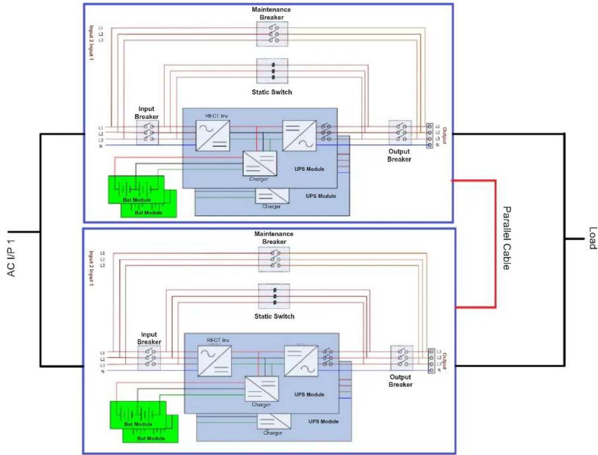
Figure 3.6 Single Input Wiring In Parallel System
3. Installation and Setup
Figure 3.7 For Dual Input Models Wiring models In Parallel System
3. Installation and Setup
3.6.2 Parallel Board Setting
3.6.2.1 Configure Parallel Board of UPS 1
- Set SW2 on the parallel board of the UPS 1 to the right side.
Figure 3.8 SW2 Position on UPS 1 (Default Setting)
3. Installation and Setup
3.6.2.2 Configure Parallel Board of UPS 2
- Set SW2 on the parallel board of the UPS 2 to the left side.
Figure 3.9 SW2 Position on UPS 2
3. Installation and Setup
3.6.3 Parallel Function Setting
- For input and output wiring, make sure to follow the instructions in section 3.6.1.
- For the parallel board setting, make sure to follow the instructions in section 3.6.2.
Confirm no power is applied to either UPS at this time.
Once the two steps above and the battery configuration have been completed correctly, proceed with the following steps:
1. Do not connect Parallel Cable until informed.
- Set the input breakers (Q1) of two UPS systems to the "ON" position. Make sure to keep the output breakers (Q3) of two UPS systems set to the "OFF" position.
- Tum on the battery breaker.
- Turn on the external AC source breaker to apply the AC input source to both UPS systems.
- Wait for the power-cycles to complete. Proceed to set UPS 1.
- Use the LCD panel on UPS 1 to set up the parallel function. Enter the "PARALLEL" menu in the "SETUP" page (refer to section 4.2.5.5 Setup-Parallel Screen for more information).
- Enable "UPS Parallel" function of UPS 1 (ignore the "Parallel UPS Cable Loose" warning).
- Choose the battery configuration as "independent" or "common" battery, depending on your preference.
- To save your settings, select the "Save Setting" icon in the "General" screen of the "SETUP" page.
- Proceed to set up UPS 2.
- Set up the parallel function through the LCD panel on UPS 2. Enter the "PARALLEL" menu in the "SETUP" page (refer to section 4.2.5.5 Setup-Parallel Screen for more information).
- Enable the "UPS Parallel" function of UPS 2 (ignore the "Parallel UPS Cable Loose" warning).
- Choose the battery configuration as "independent" or "common" battery, depending on your preference.
- To save your settings, select the "Save Setting" icon in the "General" screen of the "SETUP" page.
- Turn off the external AC source breaker and wait for complete shutdown of both UPS systems.
- Turn off the battery breakers.
3.6.4 Parallel Cable Connection
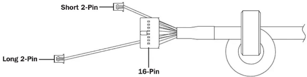
There are three connectors at the end of each parallel cable: one 16-pin connector and two 2-pin connectors.
Notes:
- For 100K and 120K UPS with One Parallel Board: Connect the 16-pin connector and the short 2-pin connector.
- For 160K and 200K UPS with Two Parallel Boards: Connect the 16-pin connector and the short 2-pin connector to the bottom board. Then, connect the long 2-pin connector to the top board.
- If the 2-pin connector is disconnected by accident, the UPS will prompt a fault: "Warning! Parallel UPS Cable Loose". Insert the 16-pin connector into CN7 and the 2-pin connector into CN10 of the Parallel Board of UPS 1. Connect the other end of the parallel cable into the Parallel Board of UPS 2, again connecting the 16-pin connector into CN7 and the 2-pin connector into CN10.
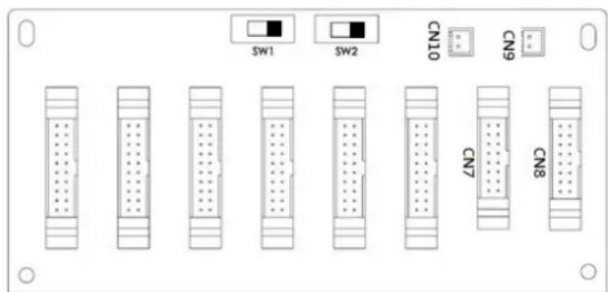
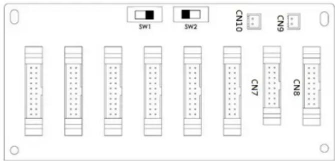
Figure 3.10 UPS 1 Parallel Board Figure 3.11 UPS 2 Parallel Board
3. Installation and Setup

Warning:
Improper parallel cable connections will result in abnormal operations. Verify each step while connecting the parallel cables on each UPS.
Confirm no power is applied to either UPS at this time.
3.6.5 Parallel System Turn On Procedure
- Make sure to follow sections 3.6.1 to 3.6.4 correctly.
- Confirm the input breaker and output breakers of each UPS have been turned "ON".
- Turn ON the battery breaker.
- Turn ON the external AC source breaker to apply AC input source to both UPS systems.
- Watch for abnormal event messages on the LCD display (refer to section 4.2.7 Event Screen for more information).
- Switch ON the UPS by pressing the power button on the UPS front panel or through the control page on the LCD panel (refer to section 4.2.3 Control Screen for more information).
3.7 Dual AC Input Installation
Dual AC Input UPS (or suffix "KXD") models are defaulted to a Single AC Input configuration via the placement of three shorting jumpers between AC Input 1 and AC Input 2. If you desire to operate the "KXD" models in a dual AC configuration, remove these three jumpers, and wire AC input 1 and AC Input 2 accordingly.
Jumperson "KXD" dual-AC input models.
4. Control Panel and LCD Operations
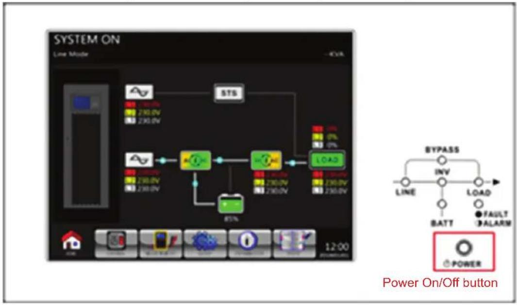
4.1 Control Panel Description
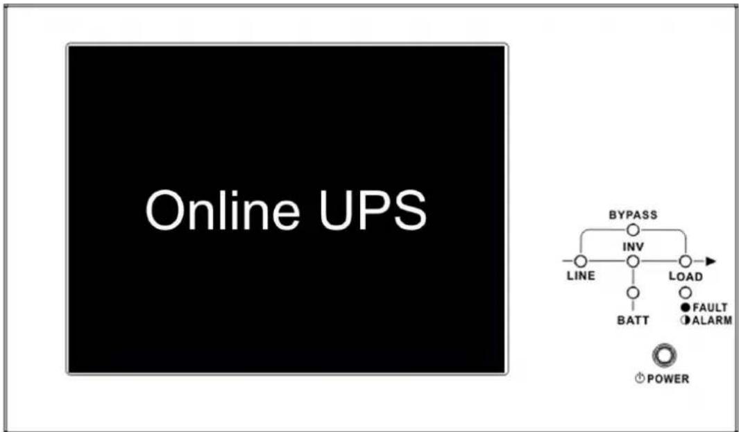
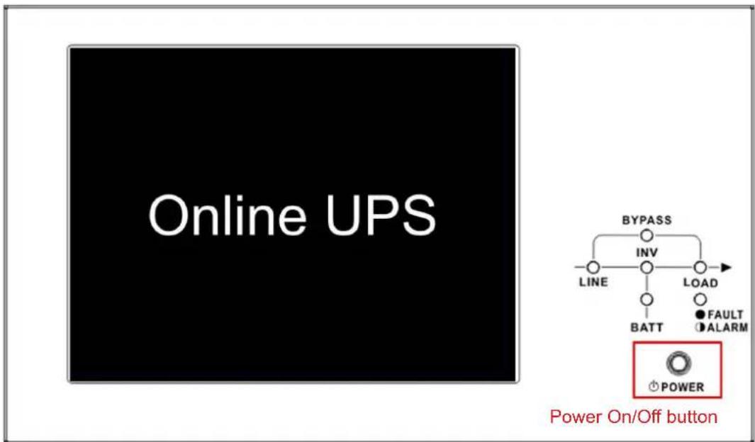
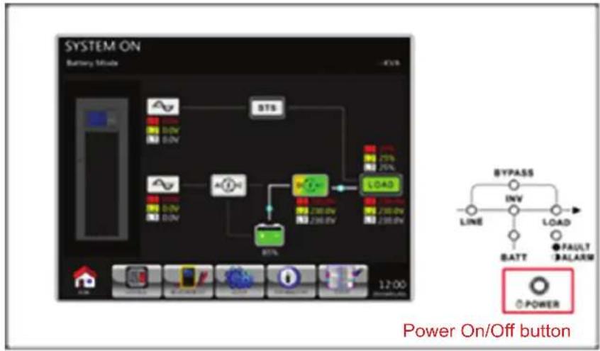
The control panel and display screen are located on the UPS front panel. This interface monitors all measured parameters, UPS status, battery status and alarms. The control interface is divided into four sections: (1) LCD panel, (2) LED indicators, (3) Power Button and (4) Audible Alarm. Refer to Figure 4.1.
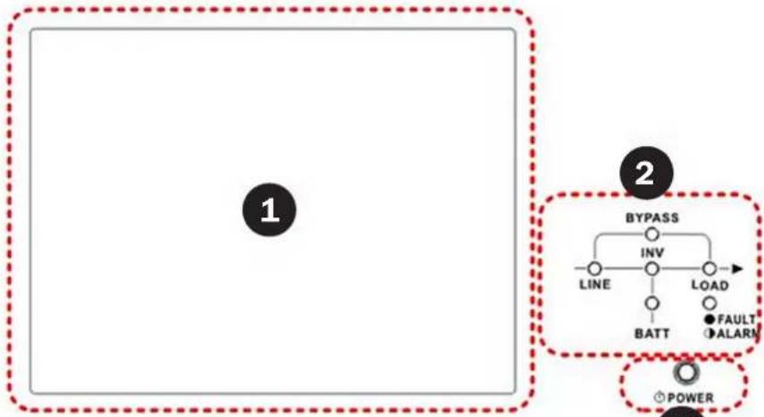
Figure 4.1 Control Panel
LCD Panel: Graphic display and all measured parameters.
2 LED Indicators: Refer to Table 4.1.
3 Power Button: Refer to Table 4.2.
4 Audible Alarm: Refer to Table 4.3.
Table 4.1: LED Indicators
| LED Colour Status | Definition | ||
| LINE Green | On Input source is normal. | ||
| Flashing Input source is abnormal. | |||
| Off No input source | |||
| BYPASS Yellow | On Load on Bypass. | ||
| Flashing Input source is abnormal. | |||
| Off Bypass not operating. | |||
| LOAD Green | On There is power output for the load. | ||
| Off There is no power output for the load. | |||
| INV Green | On Load on inverters. | ||
| Off Inverters not operating (unless in ECO Mode). | |||
| BATTERY Red | On Load on Battery. | ||
| Flashing Low battery | |||
| Off Battery converter is normal and battery is charging. | |||
| FAULT/ALARM Red | On UPS fault. | ||
| Flashing UPS alarm. | |||
| Off Normal. | |||
Table 4.2:Power Button
| Control Key | Description |
| Power On/Off | Turn on UPS or Turn off UPS (hold 2 seconds). |
Table 4.3: Audible Alarm
| UPS Condition | Description |
| Power On/Off | Buzzer sounds every 2 seconds. |
| Bypass Mode | Buzzer sounds once every minute. |
| Battery Mode | Buzzer sounds every 2 seconds. |
| Low Battery | Buzzer sounds every 0.5 seconds. |
| UPS Alarm | Buzzer sounds every 1 second. |
| UPS Fault | Buzzer sounds continuously. |
4. Control Panel and LCD Operations
4.2 LCD Screen Description
4.2.1 Initial Screen
Upon powering on, the UPS will execute POST (Power-On Self-Test). The initial screen (shown below) will display for approximately 5 seconds.

Figure 4.2 Initial Screen
4.2.2 Main Screen
After initialization, the main screen will display.
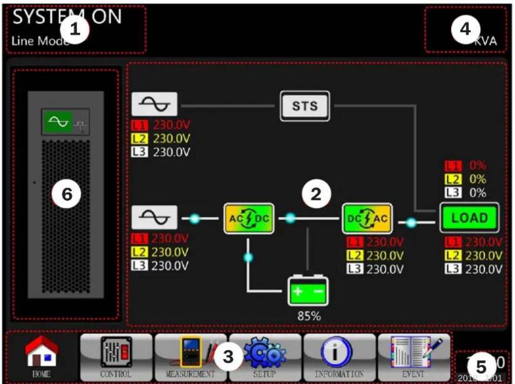
Figure 4.3 Main Screen
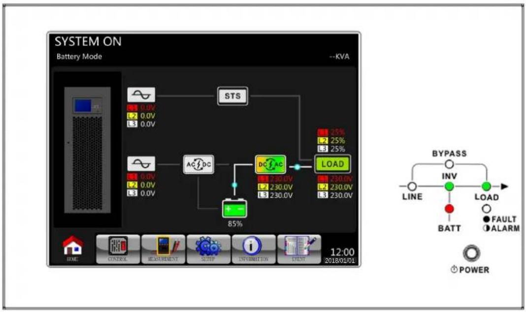
The Main Screen is divided into six sections:
UPS Operation Mode: Shows UPS current operation mode and status.
UPS Flow Chart: Shows current flow chart and measurement data.
3 Main Menu: Touch each icon to enter submenu. Refer to Figure 4.4 for menu tree.
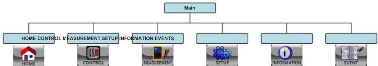
Figure 4.4 Menu Tree
4 UPS Power Rating: Shows UPS power rating.
Date and Time: Shows current date and time.
4. Control Panel and LCD Operations
UPS Status: The descriptions of each icon and its status are listed as:
| Icon UPS Status | LED Status | |
| UPS operating in Standby Mode or Shutdown Mode. LOAD - Off | ||
| UPS operating in Line Mode or Converter Mode. LINE, INV and LOAD - On | ||
| UPS operating in Bypass Mode or ECO Mode. LINE, BYPASS and LOAD - On | ||
| UPS operating in Battery Mode or Battery Test Mode. BATT, INV and LOAD - On | ||
| UPS operating in Fault Mode. FAULT - On or Flashing (Alarm) |
4.2.3 Control Screen
Touch enter into the submenu (as shown in Figures 4.5 and 4.6).
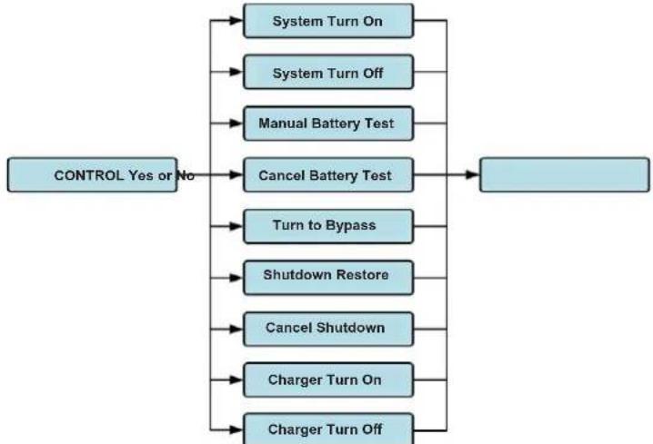
Figure 4.5 Control Screen
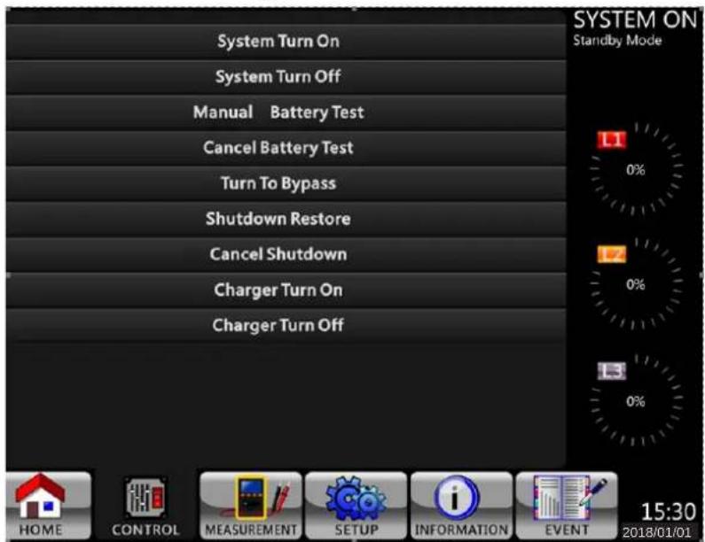
Figure 4.6 Control Menu
4. Control Panel and LCD Operations
Touch any option directly. The confirmation screen will pop up. Touch Yes to confirm command or No to cancel command.
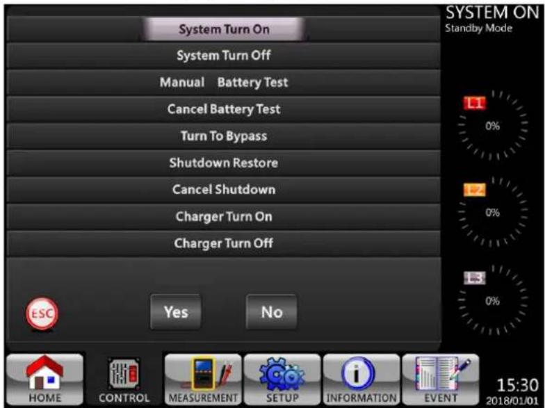
Figure 4.7 Confirmation Screen
4.2.4. Measurement Screen
to enter into the Measurement submenu. You may choose Input, Output, Bypass, Load or Battery to monitor each detailed status. Refer to Figures 4.8 and 4.9.
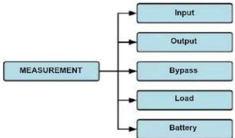
Figure 4.8 Measurement Menu
4. Control Panel and LCD Operations
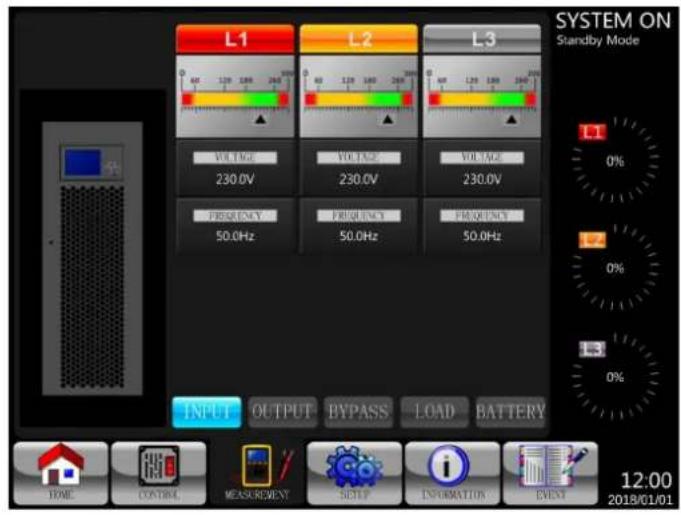
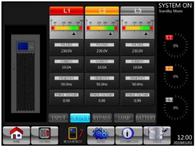
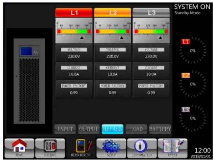
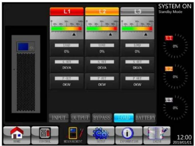
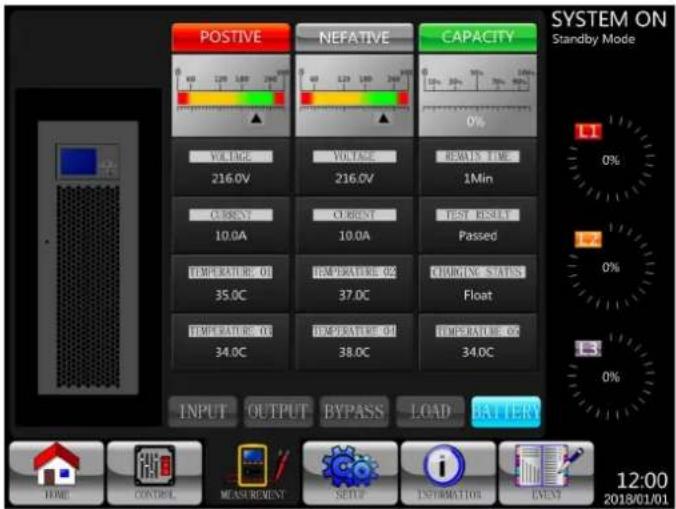
Figure 4.9 Measurement Screens: INPUT, OUTPUT, BYPASS, LOAD, and BATTERY
4. Control Panel and LCD Operations
Table 4.4: Measurement Items
| Submenu Item | Explanation | |
| Input | L-N Voltage (V) Input phase voltage (L1, L2, L3). Units: 0.1V. | |
| Frequency (Hz) Input frequency (L1, L2, L3). Units: 0.1 Hz. | ||
| Output | L-N Voltage (V) Output phase voltage (L1, L2, L3). Units: 0.1V. | |
| L-N Current (A) Output phase current (L1, L2, L3). Units: 0.1A.* | ||
| Frequency (Hz) Output frequency (L1, L2, L3). Units: 0.1 Hz. | ||
| Power Factor Output power factor (L1, L2, L3). | ||
| Bypass | L-N Voltage (V) Bypass phase voltage (L1, L2, L3). Units: 0.1V. | |
| Frequency (Hz) Bypass frequency (L1, L2, L3). Units: 0.1 Hz. | ||
| Power Factor Bypass power factor (L1, L2, L3). | ||
| Load | Sout (kVA) Apparent power. Units: 0.1kVA. | |
| Pout (kW) Active power. Units: 0.1kW. | ||
| Load Level (%) The percentage of connected load. Units: 1%. | ||
| Battery | Positive Voltage (V) Battery positive voltage. Units: 0.1V. | |
| Negative Voltage (V) Battery negative voltage. Units: 0.1V. | ||
| Positive Current (A) Battery positive current. Units: 0.1A. | ||
| Negative Current (A) Battery negative current. Units: 0.1A. | ||
| Remain Time (Sec) Battery remaining runtime. Units: 1 sec. | ||
| Capacity (%) The percentage of the battery capacity. Units: 1%. | ||
| Test Result Battery test result. | ||
| Charging Status Battery charging status. | ||
| Temperature 01(℃) Temperature of external battery pack. Units: 0.1℃. | ||
| Temperature 02(℃) Temperature of external battery pack through extra communication card T1. Units: 0.1℃. | ||
| Temperature 03(℃) Temperature of external battery pack through extra communication card T2. Units: 0.1℃. | ||
| Temperature 04(℃) Temperature of external battery pack through extra communication card T3. Units: 0.1℃. | ||
| Temperature 05(℃) Temperature of external battery pack through extra communication card T4. Units: 0.1℃. | ||
- Output current at zero load or low load may indicate up to 1% current flow on the display due to inverter activity. For load power readings, go to the LOAD submenu on the display.
4.2.5. Setup Screen
Touch the to enter into the Setup submenu. It requires a password to access the General, SYSTEM, BATTERY and PRE-ALARM submenus (as shown in Figures 4.10 and 4.11). The default password is 0000.
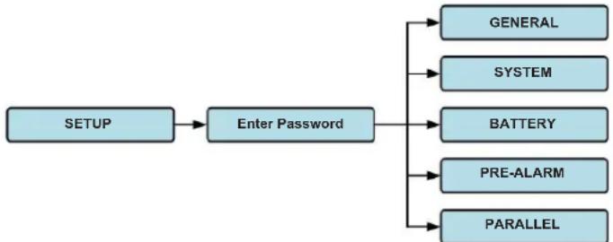
Figure 4.10 Setup Menu
4. Control Panel and LCD Operations
Touch the grey column to access the numerical keyboard. Enter a 4-digit password and press to enter the SETUP menu. If an incorrect password is entered, you may retry.
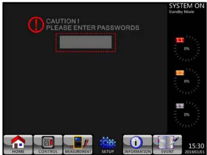
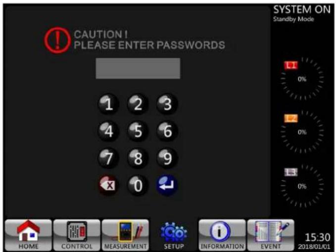
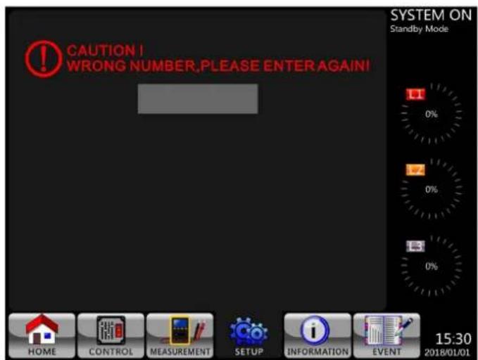
Figure 4.11 Enter Password Screens
There are two levels of password protection: user password and administrator password.
The default user password is 0000. It may be changed by the user.
The administrator password is owned by trained service personnel.
Different password levels can access different settings. The setting can be changed in various operation modes. Refer to Table 4.5 for details.
4. Control Panel and LCD Operations
Table 4.5: All Setting Items in Setup Menu
| UPS Operation Mode Setting item | Standby Mode | Bypass Mode | Line Mode | Battery Mode | Battery Test Mode | Fault Mode | Converter Mode | ECO Mode | Authorisation | ||
| User | Maintainer/Administrator | ||||||||||
| General | Model Name* YYYYYYYYY | ||||||||||
| Language** YYYYYYYYY | |||||||||||
| TIME YYYYYYYYY | |||||||||||
| Change Password YYYYYYYYY | |||||||||||
| Baud Rate YYYYYYYYY | |||||||||||
| Audible Alarm YYYYYYYYY | |||||||||||
| Factory Reset Y | |||||||||||
| EEPROM Reset Y | |||||||||||
| EPO Function Y | |||||||||||
| Save Setting | YY | YY | |||||||||
| Startup Screen | YYYYYYYYYY | ||||||||||
| System | Output Voltage | YY | Y | ||||||||
| Bypass Voltage Range | YYYYYYYYYY | ||||||||||
| Bypass Frequency Range | YY | Y | |||||||||
| Converter Mode | YY | ||||||||||
| ECO Mode YYY | YY | ||||||||||
| Bypass Mode YY | Y | ||||||||||
| Auto-Restart | YYYYYYYYYY | ||||||||||
| Cold Start | YYYYYYYYYY | ||||||||||
| Battery Mode Delay Time | YY | YYYY | |||||||||
| System Shutdown Time | YYYYYYYYYY | ||||||||||
| System Restore Time | YYYYYYYYYY | ||||||||||
| Charger Test | YY | YYYY | |||||||||
| Redundancy | YYYYYYYYYY | ||||||||||
| Battery | Battery Capacity in Ah | YY | YYYY | ||||||||
| Maximum Charging Current | YY | Y | |||||||||
| Battery Low/Shutdown Setting | YY | YYYY | |||||||||
| Periodic Battery Test | YYYYYYYYYY | ||||||||||
| Battery Test Interval | YYYYYYYYYY | ||||||||||
| Stop by Time | YY | YYYY | |||||||||
| Stop by Battery Voltage | YY | YYYY | |||||||||
| Stop by Battery Capacity | YY | YYYY | |||||||||
| Battery Age Alert | YYYYYYYYYY | ||||||||||
| Temperature Compensation | YYYYYYYYYY | ||||||||||
| Charging Voltage | YY | Y | |||||||||
| Auto-Restart Battery Voltage | YYYYYYYYYY | ||||||||||
| Pre-Alarm | Line Voltage Range | YYYYYYYYYY | |||||||||
| Line Frequency Range | YYYYYYYYYY | ||||||||||
| Load YYYYYYYYY | |||||||||||
| Parallel | UPS Parallel | YY | Y | ||||||||
| Independent Battery | YY | Y | |||||||||
"Y" indicates available options exist in each given mode.
Model names can be customised.
* English only.
4. Control Panel and LCD Operations
Setup Procedure
Step 1: Choose between GENERAL, SYSTEM, BATTERY and PRE-ALARM.
Step 2: Each item will show its current value and alternative settings.
Step 3: Choose to confirm the change or to cancel any modifications.
Figure 4.12 Setting Procedure
4.2.5.1 Setup-General Screen
The Setup-General screen and setting list options are shown in Figure 4.13 and Table 4.6.
Figure 4.13 Setup-General Screen
4. Control Panel and LCD Operations
Table 4.6: Setup-General Setting List
| Setting Item Sub Item Explanation | ||
| Model Name -- | Set UPS Name (xxxxxxxxxx).The max. length is 10 characters. | |
| Language -- English only | ||
| TIME | Adjust Time | Set current date and time.(yyyy / mm / dd hour : min : sec)MUST be set after UPS installation |
| System Installed Date | Set system installed date(yyyy / mm / dd)2018/1/1 (Default)MUST be set after UPS installation | |
| System Last Maintain Date | Set system latest maintenance date(yyyy / mm / dd)MUST be set after UPS installationMaintainer/Administrator Only | |
| Battery Installed Date | Set battery installed date(yyyy / mm / dd)MUST be set after UPS installation | |
| Battery Last Maintain Date | Set battery latest maintenance date(yyyy / mm / dd)MUST be set after UPS installation | |
| Baud Rate -- | Set SNMP Port (COM Port0) Baud Rate·2400 (Default)·4800·9600Set RS-232 Port (COM Port1) Baud Rate·2400 (Default)·4800·9600 | |
| Audible Alarm -- | Set Audible Alarm·Disable·Enable (Default) | |
| Factory Reset -- | Restore to factory default settingRefer to Table 4.7 | |
| EEPROM Reset -- | Restore EEPROM to default settingRefer to Table 4.7 | |
| EPO Function -- | Set EPO active status·Normal Close Active (Default)·Normal Open Active | |
| Password -- | Set New Password.0000 (Default) | |
| Save Setting -- | Save all settings to EEPROM.Use this feature to save the changed setting(s). Must be performed when any changes are made to the settings. | |
| Startup Screen -- | Set up initial screen. (xxxxxxxxxx).The max. length is 12 characters. | |
4. Control Panel and LCD Operations
Table 4.7: EEPROM Reset Category List
| Setting Item Factory Reset EEPROM Reset | |||
| General | Model Name | ||
| Language Y Y | |||
| Adjust Time | |||
| System Installed Date Y | |||
| System Last Maintain Date Y | |||
| Battery Installed Date Y | |||
| Battery Last Maintain Date Y | |||
| Change Password Y | |||
| Baud Rate Y | |||
| Audible Alarm Y Y | |||
| Factory Reset | |||
| EEPROM Reset | |||
| EPO Function Y | |||
| Save Setting | |||
| Startup Screen | |||
| System | Output Voltage Y | ||
| Bypass Voltage Range Y Y | |||
| Bypass Frequency Range | Y Y | ||
| Converter Mode | Y Y | ||
| ECO Mode | Y Y | ||
| Bypass Mode | Y Y | ||
| Auto-Restart | Y Y | ||
| Cold Start | Y | ||
| Battery Mode Delay Time | Y Y | ||
| System Shutdown Time | Y Y | ||
| System Restore Time | Y Y | ||
| Charger Test | |||
| Battery | Battery Capacity in Ah Y Y | ||
| Maximum Charging Current | Y Y | ||
| Battery Low/Shutdown Setting | Y Y | ||
| Periodic Battery Test | Y Y | ||
| Battery Test Interval | Y Y | ||
| Stop by Time | Y Y | ||
| Stop by Battery Voltage | Y Y | ||
| Stop by Battery Capacity | Y Y | ||
| Battery Age Alert | Y Y | ||
| Temperature Compensation | Y Y | ||
| Charging Voltage | Y Y | ||
| Auto-Restart Battery Voltage | Y Y | ||
| Pre-Alarm | Y | ||
4. Control Panel and LCD Operations
The Setup-System Screen and setting options are shown in Figure 4.14 and Table 4.8. System Setting can only be accessed when the UPS is operated in a specific mode (refer to Table 4.5 for the details). If an option is not available under a specific mode, a warning screen will appear (Figure 4.15).
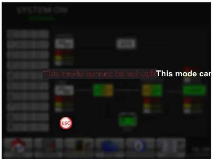
Figure 4.14 Setup-System Screen Figure 4.15 Warning Screen
Table 4.8: Setup-System Setting List
| Setting Item Sub Item Explanation | ||
| Output Voltage (Line ->N) | -- | Set output voltage ·220V AC (Default) ·230V AC ·240V AC MUST be reviewed after UPS installation |
| BYPASS SETTING | Bypass Voltage Range | Set bypass voltage range: Upper limit ·+10% ·+15% (Default) ·+20% Lower limit ·-10% ·-20% (Default) ·-30% |
| Bypass Frequency Range | Set bypass Frequency range: Upper/ Lower limit ·+/- 1 Hz ·+/- 2 Hz ·+/- 4 Hz (Default) | |
| Converter Mode -- | Set Converter Mode ·Disable (Default) ·Enable | |
| ECO Mode -- | Set ECO Mode ·Disable (Default) ·Enable | |
| Bypass Mode -- | Set Bypass Mode ·Disable ·Enable (Default, MUST be in Bypass Mode to disable) MUST be reviewed after UPS installation. If you need the Bypass power when UPS is OFF, please enable it. | |
| Auto-Restart -- | Set auto_restart ·Disable ·Enable (Default) When “Enable” is set and a UPS shutdown occurs due to low battery, the UPS will return to Line Mode once the utility power is restored. | |
| Redundancy -- | Set redundancy ·Redundancy: the QTY of unit MUST be set after UPS parallel enable | |
4. Control Panel and LCD Operations
| Setting Item Sub Item Explanation | ||
| Cold Start -- | Set cold start • Disable • Enable (Default) After “Enable” is set, the UPS can be turned on without connecting to utility by pressing Battery Start Button. Refer to cold start operation for the details (refer to 7.2 Cold Startup). | |
| Battery Mode Delay Time | -- | Set system shutdown delay time in Battery Mode (0~9990 sec). • 0: Disable (Default) • Not 0: Enable When this feature is enabled, UPS will shut off output after UPS operates in Battery Mode for the set number of seconds. |
| Shutdown/Restore | System Shutdown Time | Set system shutdown time (0.2~99 min.) • 0.2 min. (Default) This delay time will start counting when the CONTROL-Shutdown Restore command is executed. |
| System Restore Time | Set system restore time (0~9999 min.) • 1 min. (Default) This delay time will start counting after shutdown time is elapsed when the CONTROL-Shutdown Restore command is executed. | |
| Charger Test -- | Set charger test • Disable (Default) • Enable | |
4.2.5.3 Setup-Battery Screen
The Setup-Battery Screen and Setting options are shown in Figure 4.16 and Table 4.9. Battery Setting can only be set when UPS is operated in Standby Mode.
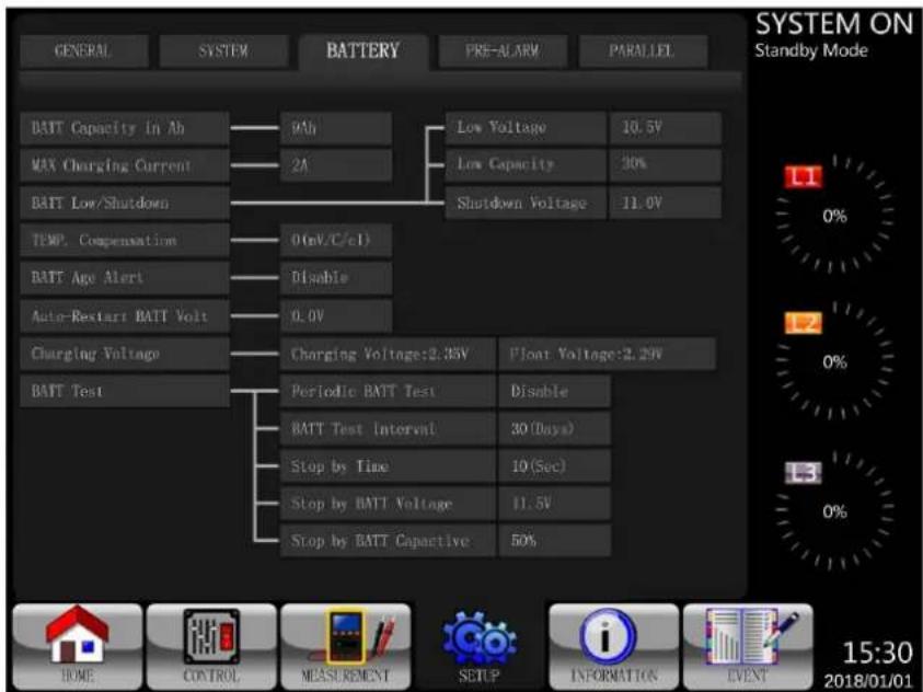
Figure 4.16 Setup-Battery Screen
4. Control Panel and LCD Operations
Table 4.9: Setup-Battery Setting List
| Setting Item Sub Item Explanation | ||
| Battery Capacity in Ah | -- | Set battery capacity. (up to 999) · 9Ah (Default) MUST be set after UPS installation or battery capacity is changed. |
| Maximum Charging Current | Recommended to Use 10% Battery Amp-Hour Rating | Set battery maximum charging current. (1~24A 100KVA/1~32A 120KVA/1~40A 160KVA/1~48A 200KVA) · 2A (Default), may be increased via the display MUST be set after UPS installation or battery capacity is changed. |
| Battery Low/ Shutdown Setting | Low Voltage | Set battery low voltage. (10 ~11.5V) x (Battery Number) · 11V x Battery Number (Default) |
| Low Capacity | Set battery low capacity. (20~50%) · 20% (Default) | |
| Shutdown Voltage (LVC) | Set battery voltage point for system shutdown in Battery Mode. (10.0V) x (Battery Number) · 10V x Battery Number (Default) | |
| Battery Test Periodic | Battery Test | Set periodic battery test disable or enable. · Disable (Default) · Enable |
| Battery Test Interval | Set battery test interval. (7~99 Days) · 30 Days (Default) | |
| Stop by Time | Set testing time for battery test. (10~1000 Seconds) · 10 sec (Default) | |
| Stop by Battery Voltage | Set stop battery voltage in battery test. (11~12V) x (Battery Number) · 11V x Battery Number (Default) | |
| Stop by Battery Capacity | Set battery capacity to stop battery testing. (20~50%) · 20% (Default) | |
| Battery Age Alert Battery Age Alert (Months) | Set battery age for replacement. (Disable, 12~60 Months) · Disable (Default) If this feature is enabled and the battery has been installed over this period, there is a "Battery Age Alert" warning to indicate it. | |
| Temperature Compensation | -- | Set battery temperature compensation. · When Enabled, 3(mV/C/cell) |
| Charging Voltage -- | Set battery charging voltage. (2.30~2.35V) · 14.1V/Battery, 2.35V/Cell (Default) Set battery float voltage. (2.23~2.35V) · 13.65V/Battery, 2.27V/Cell (Default) | |
| Auto-Restart Battery Voltage | -- | Set auto_restart battery voltage. (0 or 12.0V~13.0V) · 0V (Default) |
4. Control Panel and LCD Operations
4.2.5.4 Pre-Alarm Screen
The Pre-Alarm Screen Setup and Setting options are shown in Figure 4.17 and Table 4.10. The Pre-Alarm Setting can be accessed in any operation mode.
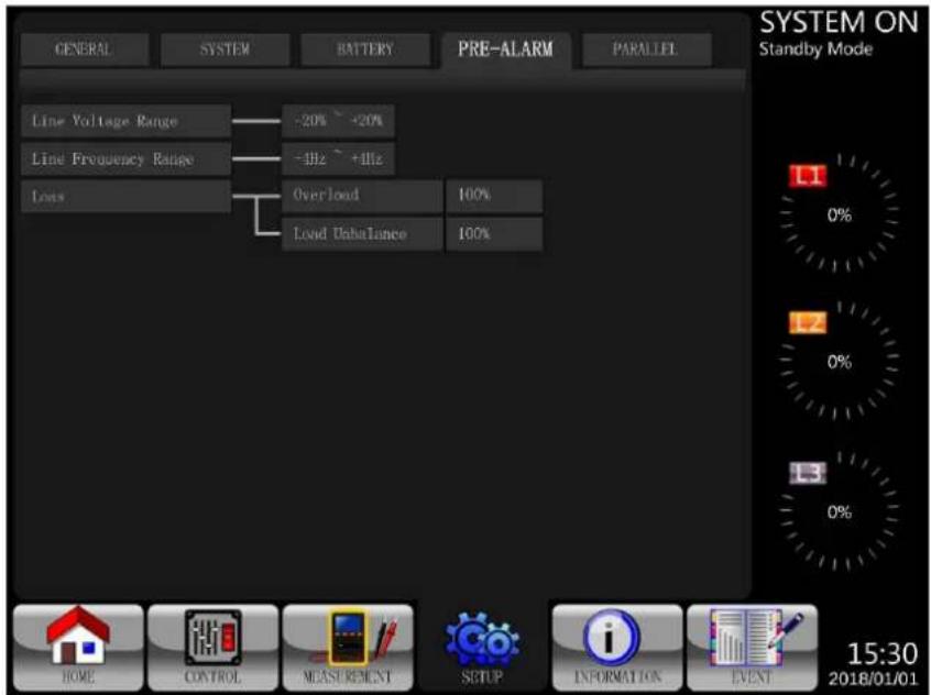
Figure 4.17 Setup-Pre-Alarm Screen
Table 4.10: Setup Pre-Alarm Setting List
| Setting Item Sub Item Explanation | ||
| Line Voltage Range -- | Set line voltage range: Upper limit • +5% • +10% • +15% • +20% (Default) Lower limit • -5% • -10% • -15% • -20% (Default) | |
| Line Frequency Range | -- | Set line frequency range: Upper / Lower limit • +/- 1 Hz • +/- 2 Hz • +/- 3 Hz • +/- 4 Hz (Default) |
| Load -- | Set UPS overload percentage (40~100%) • 100% (Default) Set UPS load unbalance percentage (20~100%) • 100% (Default) | |
4. Control Panel and LCD Operations
4.2.5.5 Setup Parallel Screen
Touch the "PARALLEL" tab to access the parallel function page. Refer to Table 4.11 for Setup Parallel Setting List.
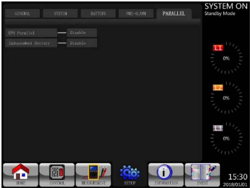
Figure 4.18 Setup Parallel Screen
Touch the "SYSTEM" tab to access the parallel or redundancy options.
(a) Paralleling two S3MX units for power. (b) Paralleling two S3MX units for redundancy, where each UPS is carrying 50% of the load. If one UPS goes down, the other will take over the full load.
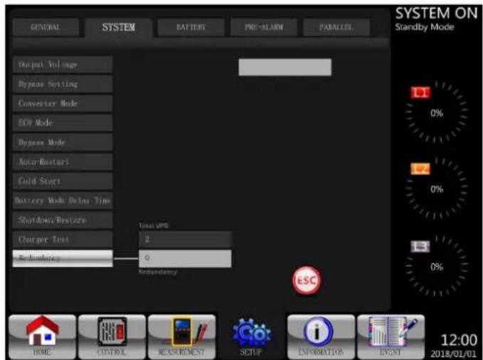
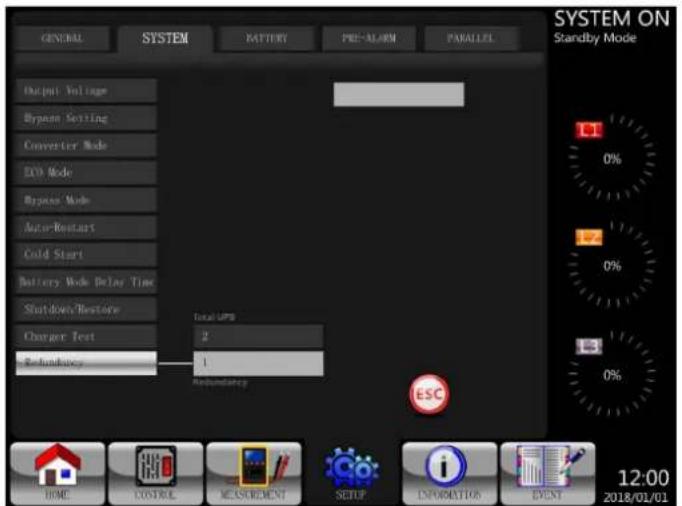
Figure 4.19 Parallel Two Units Figure 4.20 Redundancy Across Two Units
Table 4.11: Setup Parallel Setting List
| Setting Item Sub Item Explanation | ||
| UPS Parallel -- | Set UPS Parallel • Disable (Default) • Enable | |
| Independent Battery -- | Set Independent Battery • Disable (Default) • Enable | |
4. Control Panel and LCD Operations
4.2.6 Information Screen
Touch to enter the menu. In this screen, you can check the UPS configurations. There are three submen: Identification, System and Battery.
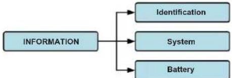
Figure 4.21 Information Menu
4.2.6.1 INFORMATION - Identification Screen
When the Identification submenu is selected, the Model Name, Serial No. and Firmware Version will display. Use the UP and DOWN arrows to switch between pages.

Figure 4.22 Identification Screen Page
4.2.6.2 INFORMATION - System Screen
When the System submenu is selected, information such as the system power, nominal voltage, nominal frequency, etc. will display. Use the UP and DOWN arrows to switch between pages.

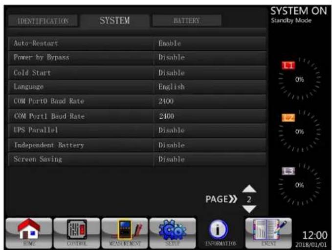
Figure 4.23 INFORMATION System Screen Page 1 Figure 4.24 INFORMATION System Screen Page 2
4. Control Panel and LCD Operations
4.2.6.3. INFORMATION - Battery Screen
When the Battery submenu is selected, information such as battery, capacity, charging current, etc., will display.
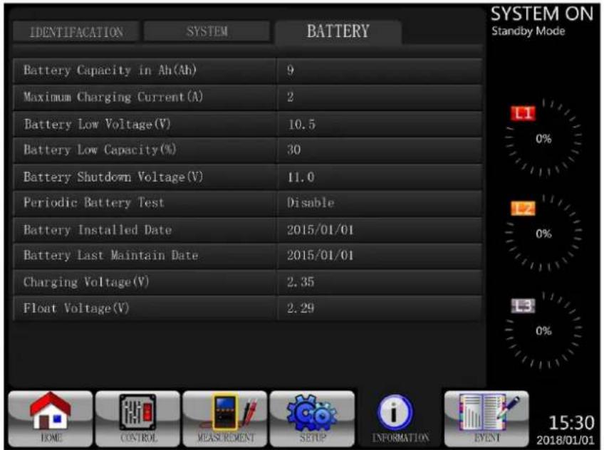
Figure 4.25 INFORMATION Battery Screen Page
4.2.7 Event Screen
When an event occurs, will flash on the main screen. You also can touch to check the latest events and history. Refer to Figure 4.27 for the menu tree.
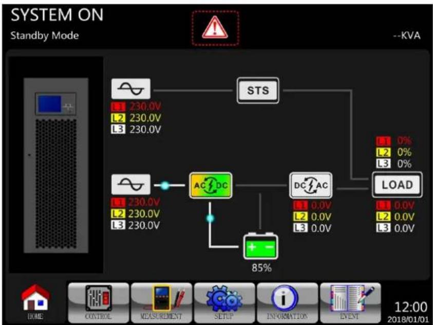
Figure 4.26 Alarm Warning Screen

Figure 4.27 Events Menu
4. Control Panel and LCD Operations
4.2.7.1 Current Events
When an event occurs, it will display the power stage ID* and alarm code on the Current Events screen. Up to 50 events can be saved, though only 10 events are listed per page. If more than 10 events are exceeded, touch PAGE to scroll to other events on the list.
Note: Refer to section 3.2 Open Front Panel to identify power stage ID.
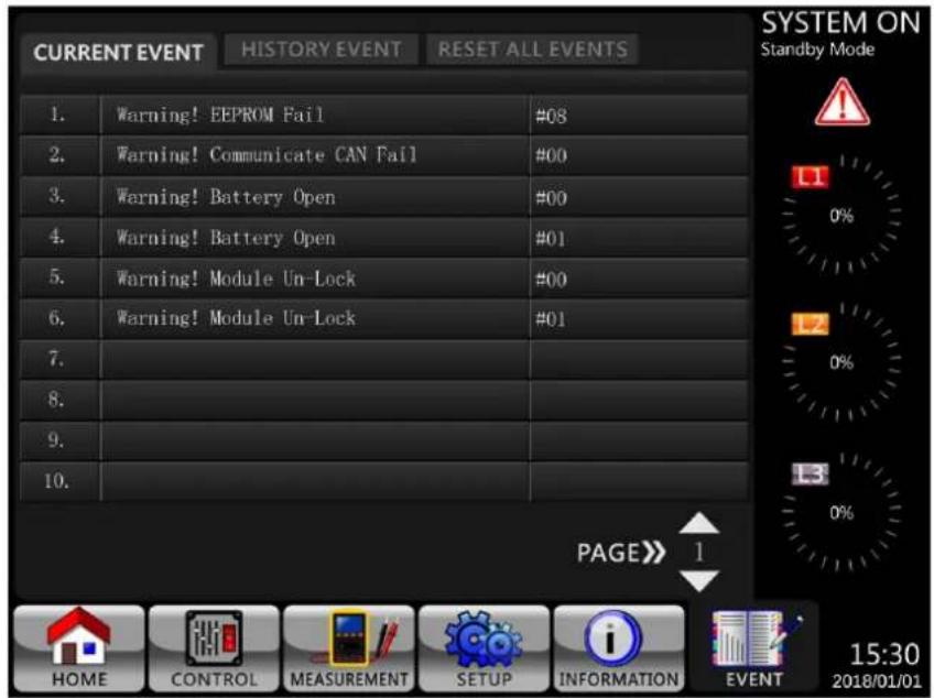
Figure 4.28 Current Events Screen
4.2.7.2 History Events
Detailed event information is saved in HISTORY EVENT. Up to 500 events can be saved. When a warning occurs, it will display the alarm code, alarm time and power stage ID (refer to section 3.2 Open Front Panel to identify power stage ID). When a fault event occurs, it will display the alarm description, alarm time and power stage ID (refer to Table 4.12). In order to record more historical information about the UPS system, the important changes in setting (Table 4.13), UPS operation mode changes (Table 4.14) and control action execution (Table 4.15) will be saved in HISTORY EVENT. Refer to Figure 4.29 for details.
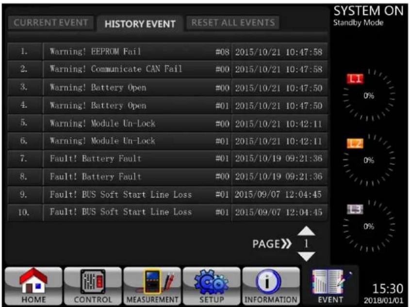
Figure 4.29 History Events Screen
4. Control Panel and LCD Operations
4.3 Alarm List
Table 4.12 provides the complete list of UPS alarm messages.
| Messages in the LCD Explanation | |
| Fault! Bus Over Voltage DC bus voltage is too high. | |
| Fault! Bus Under Voltage DC bus voltage is too low. | |
| Fault! Bus Voltage Unbalance DC bus voltage is not balanced. | |
| Fault! Bus Short DC bus is short. | |
| Fault! Bus Soft Start Time Out The rectifiers cannot start due to low DC bus voltage within specified duration. | |
| Fault! Inverter Soft Start Time Out Inverter bus voltage cannot reach desired voltage within specified duration. | |
| Fault! Inverter Voltage Over Inverter Voltage is over Peak Value. | |
| Fault! Inverter Voltage High Inverter Voltage is too high. | |
| Fault! Inverter Voltage Low Inverter Voltage is too low. | |
| Fault! R Inverter Voltage Short R phase inverter Output is short-circuited. | |
| Fault! S Inverter Voltage Short S phase inverter Output is short-circuited. | |
| Fault! T Inverter Voltage Short T phase inverter Output is short-circuited. | |
| Fault! RS Inverter Voltage Short R-S inverter Output is short-circuited. | |
| Fault! ST Inverter Voltage Short S-T inverter Output is short-circuited. | |
| Fault! TR Inverter Voltage Short T-R inverter Output is short-circuited. | |
| Fault! Inverter R Negative Power R phase inverter Output Negative Power over range. | |
| Fault! Inverter S Negative Power S phase inverter Output Negative Power over range. | |
| Fault! Inverter T Negative Power | T phase inverter Output Negative Power over range. |
| Fault! Over Load Fault | Heavy overload causes UPS fault. |
| Fault! Battery Fault | Batteries reversed. |
| Fault! Over Temperature | Make sure adequate space is allowed for air ventilation and that the fan is working. |
| Fault! CAN Fault | CAN communication fault. |
| Fault! TRIGO Fault | Synchronised trigger signal fault. |
| Fault! Relay Fault | Inverter relay fault. |
| Fault! Line SCR Fail | Line SCR short circuit fault. |
| Fault! EEPROM Fault | EEPROM operation error. |
| Fault! Parallel Cable Loose Fault | As stated. |
| Fault! DSP MCU Stop Communicate | As stated. |
| Fault! Bypass Temperature Fault | As stated |
| Fault! Bypass SCR Fault | As stated. |
| Line Fail | Utility lost or abnormal. |
| Line Restore | Utility recovered to normal. |
| Warning! EPO Active | Check the EPO connector. |
| Warning! Over Load Fail | The load devices are demanding more power than the UPS can supply. Line Mode will transfer to Bypass Mode. |
| Warning! Communicate CAN Fail | CAN communication error. |
| Warning! Over Load | When in Line Mode, the load devices are demanding more power than the UPS can supply. |
| Warning! Battery Open | Battery not connected. |
| Warning! Battery voltage High | Battery voltage is too high. |
| Warning! Turn On Abnormal | As stated. |
| Warning! Charge Fail | As stated. |
| Warning! EEPROM Fail | EEPROM operation error. |
| Warning! Fan Lock | As stated. |
| Warning! Line Phase Error | As stated. |
| Warning! Bypass Phase Error | As stated. |
| Warning! N Loss Neutral loss. | |
| Warning! Internal Initial Fail | As stated. |
| Warning! Comm Syn Signal Fail | Communicate Synchronization Signal Fail. |
| Warning! Comm. TRIGO Fail | Communicate Trigger signal fault. |
| Warning! Power Stage loss | Power stage is not detected. |
| Warning! Parallel Sys Config. Wrong | Parallel System Configure error. |
| Warning! Maintenance Bypass | Enter maintenance. |
| Warning! Battery Age Alert | Battery Life expiration. |
| Warning! Parallel UPS Cable Loose | As stated. |
4. Control Panel and LCD Operations
| Messages in the LCD Explanation | |
| Warning! Parallel UPS Config. Wrong | Parallel UPS Configure error. |
| Warning! Battery Voltage Low Battery | voltage is too low. |
| Warning! ID Conflict Power stage ID in | conflict. |
| Warning! Redundancy Set Fail As stated. | |
| Pre-Alarm! Line Voltage Fail Line voltage over range. | |
| Pre-Alarm! Line Voltage Normal Line voltage recovered to normal. | |
| Pre-Alarm! Line Frequency Unstable Line frequency over range. | |
| Pre-Alarm! Line Frequency Normal Line frequency recovered to normal. | |
| Pre-Alarm! Over Load Output Load over range. | |
| Pre-Alarm! Load Normal Output Load recovered to normal. | |
| Pre-Alarm! Load Unbalance Output Load unbalance. |
4.4 History Record
Table 4.13: Warning List For Changing Important Settings
| Item No. | Description | Item No. | Description |
| 1 | Setup! Model Name | 2 | Setup! Turn On Password |
| 3 | Setup! Language | 4 | Setup! Change Turn On Password |
| 5 | Setup! Adjust Time | 6 | Setup! Nominal Power Display |
| 7 | Setup! System Installed Date | 8 | Setup! Output Voltage |
| 9 | Setup! System Last Maintain Date | 10 | Setup! Bypass Voltage Range |
| 11 | Setup! Battery Installed Date | 12 | Setup! Bypass Frequency Range |
| 13 | Setup! Battery Last Maintain Date | 14 | Setup! Converter Mode |
| 15 | Setup! Change Password | 16 | Setup! ECO Mode |
| 17 | Setup! Baud Rate | 18 | Setup! Bypass Mode |
| 19 | Setup! Audible Alarm | 20 | Setup! Auto-Restart |
| 21 | Setup! Factory Reset | 22 | Setup! Cold Start |
| 23 | Setup! EEPROM Reset | 24 | Setup! Battery Mode Delay Time |
| 25 | Setup! EPO Function | 26 | Setup! Shutdown Restore Time |
| 27 | Setup! Save Setting | 28 | Setup! Redundancy |
| 29 | Setup! Power Rating Setting | 30 | Setup! Charger Test |
| 31 | Setup! Nominal Battery Voltage | 32 | Setup! Battery Capacity in Ah |
| 33 | Setup! Maximum Charging Current | 34 | Setup! Battery Low Voltage |
| 35 | Setup! Battery Low Capacity | 36 | Setup! Battery Shutdown Voltage |
| 37 | Setup! Periodic Battery Test | 38 | Setup! Stop By Time |
| 39 | Setup! BATTERY Age Alert | 40 | Setup! Temperature Compensation |
| 41 | Setup! Charging Voltage | 42 | Setup! PRE-ALARM |
| 43 | Setup! UPS Parallel | 44 | Setup! Independent Battery |
| 45 | Setup! Auto-Restart Battery Voltage | ||
Table 4.14:UPS Mode Changes
| Item No. | Description | Item No. | Description |
| 1 | UPS Mode! Power On Mode | 2 | UPS Mode! Standby Mode |
| 3 | UPS Mode! Bypass Mode | 4 | UPS Mode! Line Mode |
| 5 | UPS Mode! Battery Mode | 6 | UPS Mode! Battery Test Mode |
| 7 | UPS Mode! Fault Mode | 8 | UPS Mode! Converter Mode |
| 9 | UPS Mode! ECO Mode | 10 | UPS Mode! Shutdown Mode |
| 11 | UPS Mode! Un-Connection | ||
Table 4.15: Control Action Execution
| Item No. | Description | Item No. | Description |
| 1 | Control! System Turn On | 2 | Control! System Turn Off |
| 3 | Control! Manual Battery Test | 4 | Control! Cancel Battery Test |
| 5 | Control! Turn To Bypass | 6 | Control! Shutdown Restore |
| 7 | Control! Cancel Shutdown | 8 | Control! Charger Turn On |
| 9 | Control! Charger Turn Off | ||
5. Interface and Communication
The front panel contains a Battery Temperature sensor port, two Emergency Power Off Ports, a communication port (RS-232/USB), SNMP card slot and an extra communication card slot.
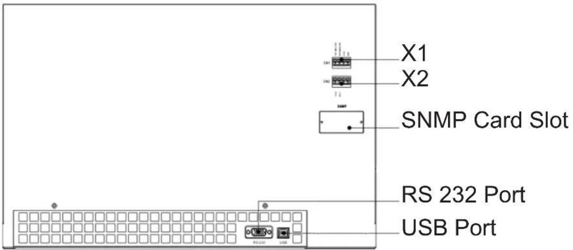
Figure 5.1 Dry Contact Ports and Communication Ports
| Dry Contact No. Function |
| X1 Battery Temperature Detection Thermostat Port |
| X2 Remote EPO Input Port |
5.1. X1 - Temperature Detection Port for External Battery Pack
The UPS is equipped with a battery temperature detection function. The UPS can receive a battery temperature signal through the temperature detection thermostat board. Communication between the UPS and battery temperature detection thermostat board is via I2C communication protocol. X1 is the battery temperature detection port. The port is shown in Figure 5.2 and described in Table 5.1.
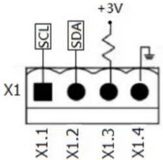
Figure 5.2 Battery Temperature Detection Port
Table 5.1 Description of Battery Temperature Detection Port
| Name Position Description | ||
| SCL X1.1 I2C communication SCL Signal | ||
| SDA X1.2 I2C communication SDA Signal | ||
| +3.0V X1.3 3V | ||
| Power GND X1.4 GND |
5. Interface and Communication
5.2 X2 - Remote EPO Input Port
The UPS is equipped with Emergency Power Off (EPO) Function that can be operated by a remote contact assigned by the users. EPO is defaulted to Normally Closed (N.C.).
Note: The open contact activates EPO function.
Users may change the setting to Normally Open via the LCD display.
X2 is the remote EPO input port. This port is shown in Figure 5.3 and described in Table 5.2.
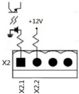
Figure 5.3 Remote EPO Input Port
Table 5.2 Description of Remote EPO Port
| EPO Logic Setting Position Description | ||
| N.C X2.1 and X2.2 EPO activated when Opened X2.1 and X2.2 | ||
| N.O X2.1 and X2.2 EPO activated when Shorted X2.1 and X2.2 |
If EPO Logic setting is Normally Closed (N.C), the EPO will be triggered when pins 1 and pin 2 of X1 are opened. Otherwise, EPO Logic setting is Normal Opened (N.O). The EPO will be triggered when pins 1 and pin 2 of X2 are closed.
Notes:
- EPO function shuts down the rectifiers, chargers, inverters and static transfer switch, but it does not internally disconnect the input power supply.
- The default setting of the EPO function logic is Normal Closed (N.C).
- A user-supplied REPO button must be latching type and in a normally closed position.
5.3 Other Communication Interfaces
5.3.1 RS-232 Port
The RS-232 port is located on the panel behind the front door. The RS-232 port provides service support when upgrading the UPS software to a different revision.
5.3.2 USB Port
This port is for service purposes only.
Note: The RS232 and USB ports WILL NOT work simultaneously.
5.3.3. SNMP Slot for Monitoring Using WEBCARDLX (Optional cards)
Install an optional WEBCARDLX card in this slot to remotely monitor and control the UPS via network. The RELAYCARDSV may also be inserted in this slot to provide dry contact I/P and O/P signals and temperature sensors communication functionality. Refer to the WEBCARDLX and RELAYCARDSV manuals for further details.
Note: Only one card may be used at a time.
6. Operation Principles
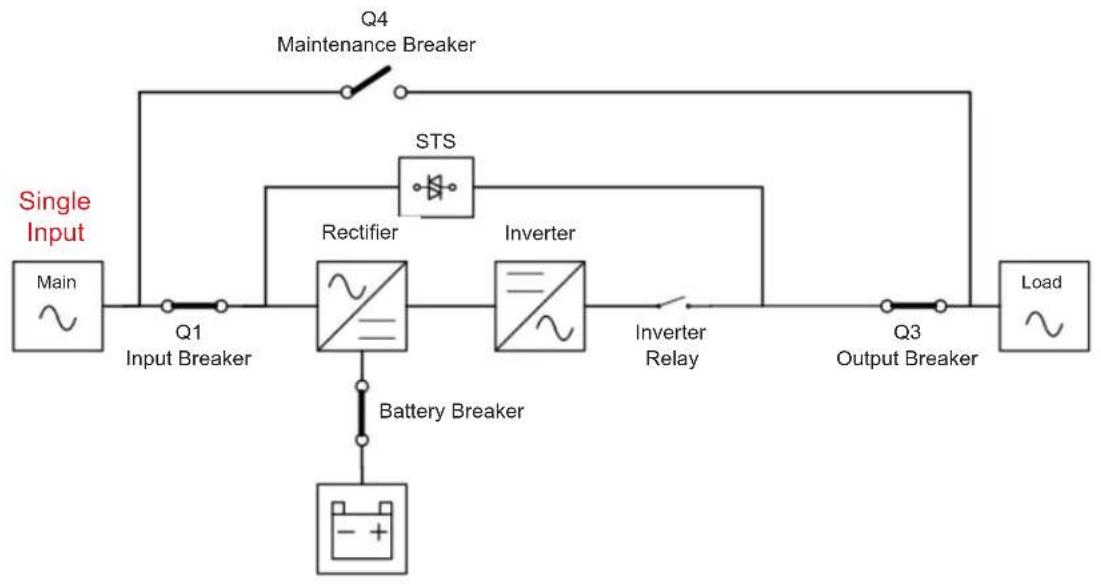
6.1 UPS Block Diagram
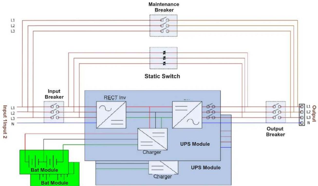
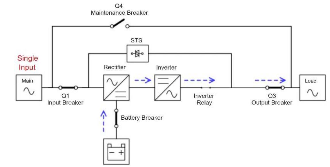
Figure 6.1 Wiring Diagram for a Standard Single Input UPS
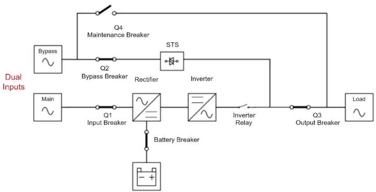
Figure 6.2 Wiring Diagram for Dual Inputs (Offered on a Different S3MX UPS Model)
6. Operation Principles
6.2 Operation Modes
This UPS is a 3-phase, four wire on-line, double-conversion and reverse-transfer UPS that permits operation in the following modes:
- Standby Mode
- Line Mode
- Battery Mode
- Bypass Mode
- Converter Mode
ECO Mode - Shutdown Mode
- Maintenance Bypass Mode (Manual Bypass)
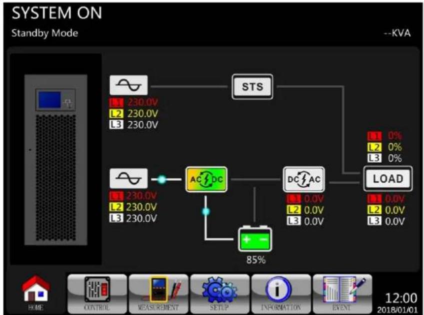
6.2.1 Standby Mode
The UPS will enter Standby Mode (if BYPASS is disabled) until the UPS is turned on. When the UPS is powered on in Standby Mode, the charger function will be active when the battery is connected. The load is not powered under this mode.
Standby Mode Diagrams
6. Operation Principles
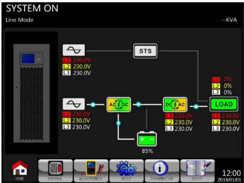
6.2.2 Line Mode
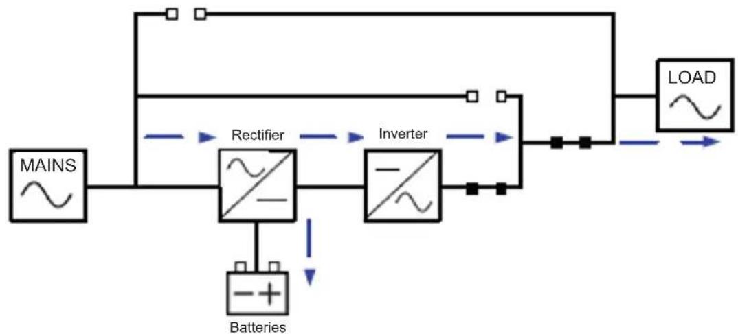
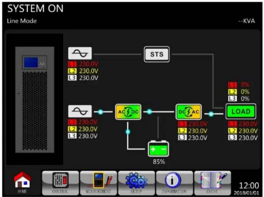
In Line Mode, the rectifier delivers power from the mains and supplies DC power to the inverter and the charger charges the battery. The inverter filters the DC power and converts it into pure, stable AC power to power the load.
Line Mode Diagrams
6. Operation Principles
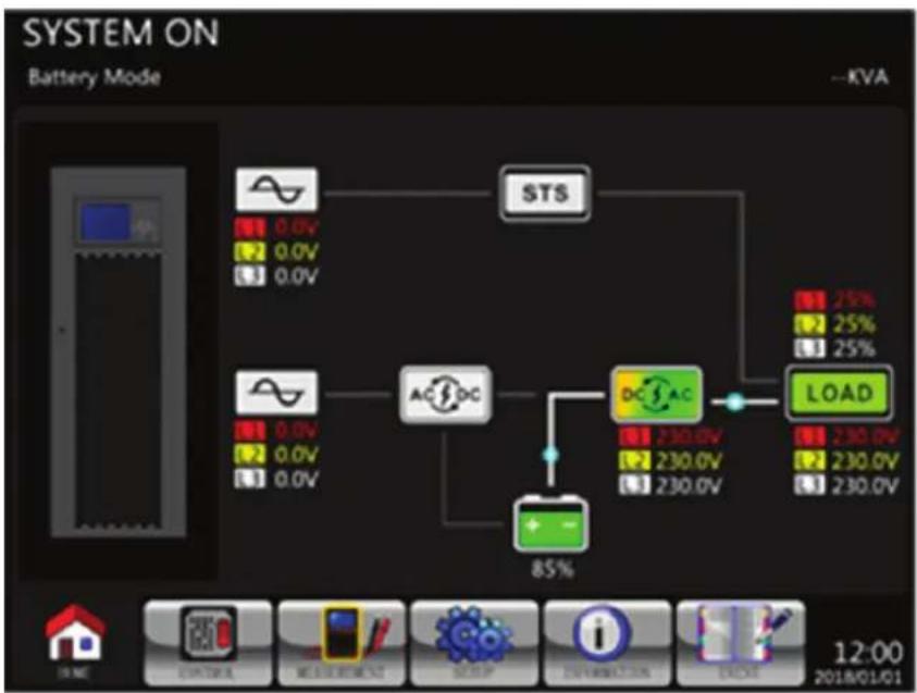
6.2.3 Battery Mode
The UPS automatically transfers to Battery Mode if the Utility fails. There is no interruption to the load upon failure. In Battery Mode, the rectifier delivers power from the battery and supplies DC power to the inverter. The inverter filters the DC power and converts it into pure and stable AC power to power the load.
Battery Mode Diagrams
6. Operation Principles
6.2.4 Frequency Conversion Mode
When the UPS is manually set in Converter Mode, the output frequency can be set as 50Hz or 60Hz . After the output frequency is set up, the system will automatically disable the bypass function. Once the inverter shuts down, there is no bypass output. During Converter Mode, the NORMAL LED indicator (NORMAL) illuminates (green).
Frequency Conversion Mode Diagram
6. Operation Principles
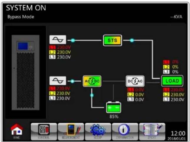
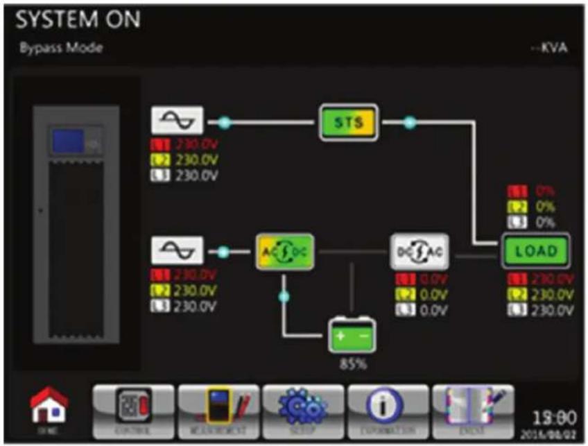
6.2.5 Bypass Mode
Upon connecting to utility input power, the UPS is in Bypass Mode before the UPS is turned on (if BYPASS setting is enabled), and charger function will be active when battery is connected.
If the UPS has been turned on and encounters abnormal situations (over-temperature, overload, etc.), the static transfer switch will transfer the load from the inverter to the bypass source with no interruption. If the transference was caused by a recoverable reason, the UPS will return to Line Mode once the situation has been resolved.
Bypass Mode Diagrams
6. Operation Principles
6.2.6 ECO Mode
ECO Mode can be enabled through the LCD control panel. In ECO Mode, the load is diverted to bypass when the bypass voltage and frequency are within their acceptable range. If the bypass voltage is out of range, the UPS will transfer the power source from bypass to inverter. In order to shorten the transfer time, the rectifier and inverter will be operating when the UPS is in ECO Mode.
ECO Mode Diagrams
6. Operation Principles
6.2.7 Shutdown Mode
When the UPS is in the off state and utility power source is absent, the UPS will enter Shutdown Mode. When the utility power source is absent and the UPS has discharged the batteries to the cut-off voltage level of 10V/battery at 25C, the UPS will also enter into a Shutdown Mode. When the UPS enters this mode, it will shut off the control power of the UPS and rectifier, and shut down the charger and inverter.
Shutdown Mode Diagrams
6. Operation Principles
6.2.8 Maintenance Bypass Mode
A manual bypass switch is available to ensure continuity of supply to the critical load when the UPS becomes unavailable (e.g. during a maintenance procedure). Before entering the Maintenance Bypass Mode, make sure the bypass power source is available.
Maintenance Bypass Mode Diagrams
7. UPS Operation

WARNING
- Do not start the UPS until the installation is completed.
- Make sure the wiring is connected correctly and power cables are firmly fixed.
- Make sure the Power Stages' addresses have been configured correctly. Refer to section 3.3 and Table 3.1 for details.
- Make sure all breakers are switched OFF.
7.1 AC Startup
Use the following procedures when turning on the UPS from a fully "powered-down" state.
Step 1: Apply utility power to the UPS.
Step 2: Turn ON the battery breaker (external battery cabinet).
Step 3: Turn ON the Input breaker (Q1).
For Dual Input models: Turn ON both the Input breaker (Q1) and Bypass breaker (Q2).
Step 4: Wait one minute. The LCD panel is displayed as shown below. The UPS will enter Bypass Mode if the setting of Bypass Mode is enabled (default setting). If Bypass Mode is disabled, the UPS will remain in Standby Mode.

7. UPS Operation
Step 5: Make sure there are no warning or fault events recorded. However, if there is a warning or fault event, please refer to 8. Troubleshooting to resolve the issue.
Step 6: Turn ON the Output breaker (Q3).
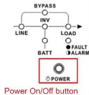
Step 7: Press the Power ON/OFF button for two seconds until a beep is heard, then release to start the inverter.
Step 8: The UPS is now in Line Mode. AC startup is now complete.
7. UPS Operation
7.2. Cold Start Startup
Step 1: Switch ON the battery breaker (external battery cabinet).
Step 2: Press the "Battery Start" button on any one of power stages to start up the control power.
Step 3: After pressing the "Battery Start" button, the UPS will display the initialization screen.
Step 4: While the UPS is displaying the Online screen, immediately press the "Power On/Off" button for 2 seconds until a beep is heard, then release to start the inverter.
7. UPS Operation
Step 5: The UPS will enter Battery Mode.
Step 6: Switch ON the output breaker (Q3). The cold start startup procedure is complete.
Step 7: Turn on the Input Breaker (Q1) when utility power is restored and verified OK.
For Dual Input models: Turn ON the Input breaker (Q1) and Bypass breaker (Q2) when utility power is restored and verified OK.
7. UPS Operation
7.3 Maintenance Bypass Operation
Follow the below steps to transfer to maintenance bypass for power stage maintenance and UPS protection.
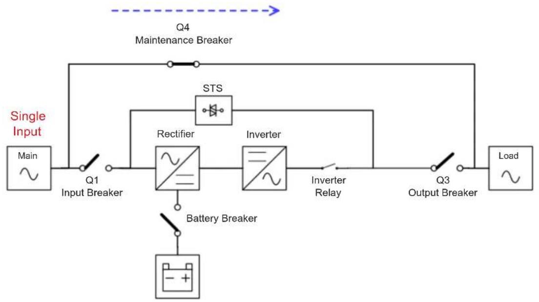
7.3.1 Transfer Critical Load from Line Mode to Maintenance Bypass

Confirm Bypass Mode is enabled via the LCD display menu prior to performing the Maintenance Bypass procedure.
| Step 1 | Remove the mechanical locking plate securing the Q4 Maintenance Bypass breaker (all models). | |
| S3M100KX/S3M100KXD S3M120KX/S3M120KXD (100 kVA/120 kVA) Models | S3M160KX/S3M160KXD S3M200KX/S3M200KXD (160 kVA/200 kVA) Models | |
| Step 2 | Confirm the UPS is operating in Bypass Mode. | |
| SYSTEM ON Bypass Mode -KVA STS 230.0V 230.0V ACDC 230.0V 230.0V + - 0% 0% 0% LOAD 230.0V 230.0V 230.0V 12:00 2018/01/01 | ||
| Step 3 | Turn ON the Q4 Maintenance Bypass breaker (all models). | |
| ON OFF Q4 Maintenance Bypass S3M100KX/S3M100KXD S3M120KX/S3M120KXD (100 kVA/120 kVA) Models | ONOFF Q4 Maintenance Bypass S3M160KX/S3M160KXD S3M200KX/S3M200KXD (160 kVA/200 kVA) Models | |
7. UPS Operation
| Step 4 | Turn OFF the Q3 Output breaker. S3M100KX/S3M100KXD S3M120KX/S3M120KXD (100 kVA/200 kVA) Models | Turn OFF the Q3 Output breaker. S3M160KX/S3M160KXD S3M200KX/S3M200KXD (160 kVA/200 kVA) Models |
| Step 5 Single input model: Turn OFF the Q1 Input 1 breaker. Q1 Input 1 S3M100KX S3M120KX (100 kVA/200 kVA) Models | Single input model: Turn OFF the Q1 Output breaker. Q1 Input 1 S3M160KX S3M200KX (160 kVA/200 kVA) Models | |
| Dual input models (Optional): Turn OFF the Q1 Input breaker and Q2 Input breaker. Q1 Input 1 S3M100KXD S3M120KXD (100 kVA/200 kVA) Models | Dual input models (Optional): Turn OFF the Q1 Input breaker, Q2 Input breaker. Q1 Input 1 S3M160KXD S3M200KXD (160 kVA/200 kVA) Models | |
| Step 6 | The UPS will enter Shutdown Mode and will slowly de-energise. After the UPS powers off, turn OFF the battery breaker (external battery cabinet). | |
| Step 7 | The critical load is now supported in Maintenance Bypass Mode. | |
7. UPS Operation
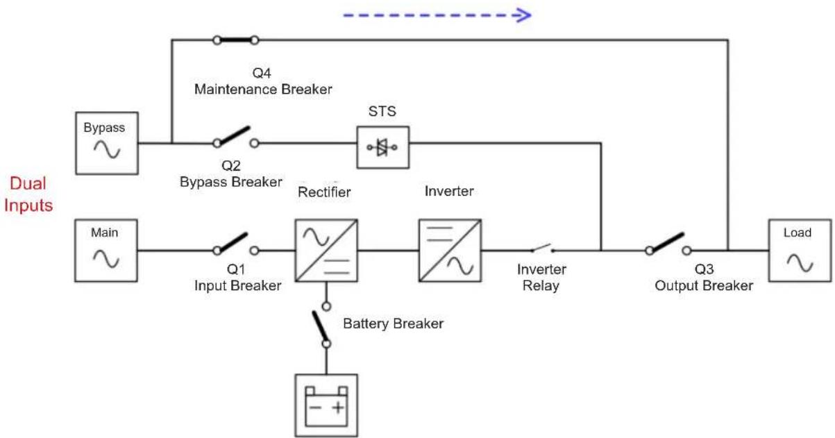
7.3.2 Transfer Critical Load from Maintenance Bypass to Line Mode
| Step 1 | Turn ON the battery breaker (external battery cabinet). | |
| Step 2 Single input model: Turn ON the Q1 Input 1 breaker. S3M100KX S3M120KX (100 kVA/200 kVA) Models | Single input model: Turn ON the Q1 Input 1 breaker. S3M160KX S3M200KX (160 kVA/200 kVA) Models | |
| Dual input model (Option): Turn ON the Q1 Input breaker and Q2 Input breaker. Q1 Input 1 S3M100KXD S3M120KXD (100 kVA/200 kVA) Models | Dual input model (Option): Turn ON the Q1 Input breaker and Q2 Input breaker Q1 Input 1 S3M160KXD S3M200KXD (160 kVA/200 kVA) Models | |
| Step 3 | Go to the LCD INFORMATION Menu. Choose "SYSTEM" to ensure that Bypass Mode is enabled ("Power By Bypass"). If Bypass Mode is disabled, set it to "enabled" through the SETUP menu and confirm the UPS is operating in Bypass Mode before proceeding. | |
| Step 4 | Turn ON the Q3 Output breaker. Q3 Output S3M100KX/S3M100KXD S3M120KX/S3M120KXD (100kVA/120kVA) Models | Turn ON the Q3 Output breaker. Q3 Output S3M160KX/S3M160KXD S3M200KX/S3M200KXD (160 kVA/200 kVA) Models |
7. UPS Operation
| Step 5 | Turn OFF the Q4 Maintenance Bypass breaker (all models). | |
| ON OFF Q4 Maintenance Bypass S3M100KX/S3M100KXD S3M120KX/S3M120KXD (100 kVA/200 kVA) Models | ONOFF Q4 Maintenance Bypass S3M160KX/S3M160KXD S3M200KX/S3M200KXD (160 kVA/200 kVA) Models | |
| Step 6 | Secure the mechanical locking plate to the Q4 Maintenance Bypass breaker (all models). | |
| S3M100KX/S3M100KXD S3M120KX/S3M120KXD (100 kVA/200 kVA) Models | S3M160KX/S3M160KXD S3M200KX/S3M200KXD (160 kVA/200 kVA) Models | |
| Step 7 | Press Power ON/OFF button for 2 seconds until a beep is heard, then release to start the inverter. | |
| Step 8 | The critical load is now supported in Line Mode. | |
7. UPS Operation
7.4 Turn Off Operation
7.4.1 Turn Off Operation in Line Mode

WARNING: The UPS system shutdown procedure will eliminate the AC power output for all loads. Before shutdown, confirm all power loads are turned off.
The LCD diagrams shown below are when the UPS is operating in Line Mode.
Step 1: Stop the inverter. Press the "Power On/Off" button for 2 seconds until a beep is heard to turn off the UPS, or use the MenuControl-System. The UPS will transfer to Bypass Mode - or Standby Mode if the Bypass Mode setting is disabled.
7. UPS Operation
The LCD diagram below is showing Bypass Mode (Bypass Mode is enabled).
Step 2: Turn off the Output Breaker (Q3).
Step 3: Turn off the Input Breaker (Q1).
For Dual Input models: Turn off the Input Breaker (Q1) and Bypass Breaker (Q2).
Step 4: The UPS will enter Shutdown Mode and slowly de-energise. Wait until the LCD is OFF.
Step 5: After the UPS powers off, switch OFF the external power switch to disconnect the AC power to the UPS.
Step 6: If the UPS will remain disconnected from the AC power for an extended period, switch OFF the battery breaker (external battery cabinet).
7.4.2 Turn Off Operation in Battery Mode

WARNING: The UPS system shutdown procedure will eliminate the AC power output for all loads. Before shutdown, confirm all power loads are turned off.
The LCD diagrams shown below are when the UPS is operating in Battery Mode.
7. UPS Operation
Step 1: Press the "Power On/Off" button for 2 seconds to turn off the UPS, or use the Menu-Control-System. The UPS will first transfer to Standby Mode, then Shutdown Mode after a few seconds.
Step 2: Turn off the Output Breaker (Q3).
Step 3: Turn off the Input Breaker (Q1).
For Dual Input models: Turn off the Input Breaker (Q1) and Bypass Breaker (Q2).
Step 4: While in Shutdown Mode the UPS will slowly de-energise. Wait until the LCD is OFF.

Step 5: After the UPS powers off, switch OFF the external power switch to disconnect the AC power to the UPS.
Step 6: If the UPS will remain disconnected from the AC power for an extended period, switch OFF the battery breaker (external battery cabinet).
8. Troubleshooting
Fault and Warning events should be reviewed by authorised service personnel.
| LCD Message Explanation Solution | ||
| Fault! Bus Over Voltage DC bus voltage is too high. Contact service personnel. | ||
| Fault! Bus Under Voltage DC bus voltage is too low. Contact service personnel. | ||
| Fault! Bus Voltage Unbalance DC bus voltage is not balanced. Contact service personnel. | ||
| Fault! Bus Short DC bus is short. Contact service personnel. | ||
| Fault! Bus Soft Start Time Out The rectifiers could not start due to low DC bus voltage within specified duration. | Turn off UPS and then restart the UPS. If it fails again, contact service personnel. | |
| Fault! Inverter Soft Start Time Out Inverter voltage cannot reach desired voltage within specified duration. | Turn off UPS and then restart the UPS. If it fails again, contact service personnel. | |
| Fault! Inverter Voltage Over Inverter Voltage over (Peak Value). Contact service personnel. | ||
| Fault! Inverter Voltage High Inverter Voltage is too high. Contact service personnel. | ||
| Fault! Inverter Voltage Low | Inverter Voltage is too Low. Contact service personnel. | |
| Fault! R Inverter Voltage Short | R phase inverter Output is shorted. | Contact service personnel. |
| Fault! S Inverter Voltage Short | S phase inverter Output is shorted. | Contact service personnel. |
| Fault! T Inverter Voltage Short | T phase inverter Output is shorted. | Contact service personnel. |
| Fault! RS Inverter Voltage Short | R-S inverter Output is shorted. | Contact service personnel. |
| Fault! ST Inverter Voltage Short | S-T inverter Output is shorted. Contact service personnel. | |
| Fault! TR Inverter Voltage Short | T-R inverter Output is shorted. Contact service personnel. | |
| Fault! Inverter R Negative Power | R phase inverter Output Negative Power over range. | Contact service personnel. |
| Fault! Inverter S Negative Power | S phase inverter Output Negative Power over range. | Contact service personnel. |
| Fault! Inverter T Negative Power | T phase inverter Output Negative Power over range. | Contact service personnel. |
| Fault! Over Load Fault | Heavy overload causes UPS fault. | Reduce some load. |
| Fault! Battery Fault | Battery reverse. | Check the polarity of battery connection and contact service personnel. |
| Fault! Over Temperature | Make sure adequate space is allowed for air vents and the fan is working. | Check if the ambient temperature is over specification or contact service personnel. |
| Fault! CAN Fault CAN communication fault. Contact service personnel. | ||
| Fault! TRIGO Fault | Synchronised trigger signal fault. | Contact service personnel. |
| Fault! Relay Fault | Inverter relay fault. | Contact service personnel. |
| Fault! Line SCR Fail | Line SCR short circuit fault. | Contact service personnel. |
| Fault! EEPROM Fault | EEPROM operation error. | Contact service personnel. |
| Fault! Parallel Cable Loosen Fault | As stated. | Check if the parallel cable is loose and contact service personnel. |
| Fault! DSP MCU Stop Communicate | As stated. | Contact service personnel. |
| Fault! Bypass Temperature Fault | As stated. | Check if the ambient temperature is over specification or contact service personnel. |
| Fault! Bypass SCR Fault | As stated. | Contact service personnel. |
| Warning! EPO Active | Check the EPO connector. | Check if the connector is loose when EPO acts abnormally. |
| Warning! Over Load Fail | The load devices are demanding more power than the UPS can supply. Line Mode will transfer to Bypass Mode. | Reduce some load and check output Load-Capacity and specification. |
| Warning! Communicate CAN Fail | CAN communication error. | Contact service personnel. |
| Warning! Over Load | When in Line Mode, the load devices are demanding more power than the UPS can supply. | Reduce some load and check output Load-Capacity and specification. |
| Warning! Battery Open | Battery not connected. | 1. Check battery breaker.2. Check if the battery connection is well connected.3. Check the setting of Nominal Battery voltage.4. Contact service personnel if necessary. |
| Warning! Battery voltage High | Battery voltage is too High. | Check the setting of Nominal Battery voltage and contact service personnel. |
| Warning! Turn On Abnormal | As stated. | Check if the input voltage or frequency is out of range. |
| Warning! Charge Fail | As stated. | Contact service personnel. |
| Warning! EEPROM Fail | EEPROM operation error. | Contact service personnel. |
| Warning! Fan Lock | As stated. | Check if the fan is blocked or contact service personnel. |
8. Troubleshooting
| LCD Message Explanation Solution | ||
| Warning! Line Phase Error As stated. Check if the Mains phase sequence is correct and contact service personnel. | ||
| Warning! Bypass Phase Error As stated. Check if the Bypass phase sequence is correct and contact service personnel. | ||
| Warning! N Loss Neutral loss. Check if the Neutral connection is correct and contact service personnel. | ||
| Warning! Internal Initial Fail As stated. Contact service personnel. | ||
| Warning! Comm. Syn. Signal Fail Communicate Synchronization Signal Fail. Contact service personnel. | ||
| Warning! Comm. TRIGO Fail Communicate Trigger signal fault. Contact service personnel. | ||
| Warning! Power Stage Loss As stated. Check if the number of power stages installed in the system is correct | ||
| Warning! Parallel Sys Config. Wrong Parallel System Configure error. Contact service personnel. | ||
| Warning! Maintenance Bypass Enter maintenance. Check if the connector is loose when it acts abnormally. | ||
| Warning! Battery Age Alert | Battery Life expiration. | Check if the battery has been used over its service age or contact service personnel. |
| Warning! Parallel UPS Cable Loosen | As stated. Check if the Parallel UPS Cable is loose and contact service personnel. | |
| Warning! Parallel UPS Config. Wrong | Parallel UPS Configure error. | Check that the Parallel UPS Setting is correct and contact service personnel. |
| Warning! Parallel Firmware Error | Power Stage parallel firmware error. | The firmware version does not support UPS Parallel feature. Contact service personnel. |
| Warning! ID Conflict | Power Stage ID conflict. | There are two Power Stages with the same ID numbers. Change the repeated ID to release it or contact service personnel. |
| Warning! Redundancy Set Fail | As stated. Check if the UPS is set from parallel to single. The Redundancy setting needs to be set to 0. | |
9. Storage and Service
9.1 Storage
The UPS system must be stored in a clean, secure environment with a temperature less than 40^ and a relative humidity less than 90% (non-condensing). Store the UPS system in its original shipping container, if possible. If installation occurs more than 6 months after you receive the UPS system, recharge the batteries for at least 24 hours prior to use. Do not rely on the UPS system to provide backup power to connected equipment until the batteries are fully charged.
Note: If the UPS system remains off for an extended period of time, it should be turned on periodically to allow the batteries to recharge. The UPS system should be turned on and the batteries should be recharged at least one uninterrupted 24-hour period every 3 months. Failure to recharge the batteries periodically may cause irreversible battery damage.
9.2 Service
- The UPS system operates with hazardous voltages. Repairs should only be performed by qualified service personnel.
- Even after the unit is disconnected from the mains, potentially dangerous components inside the UPS system are still connected to the battery packs.
- Before carrying out any service and/or maintenance, disconnect the batteries and verify that no current is present and no hazardous voltage exists.
- Only qualified technicians taking the required precautionary measures may replace batteries and supervise operations. Unauthorized persons should not perform battery maintenance.
- Verify that no voltage between the battery terminals and the ground is present before maintenance or repair. The battery circuit is not isolated from the input voltage. Hazardous voltages may occur between the battery terminals and the ground.
- Batteries may cause electric shock and have a high short-circuit current. Remove all wristwatches, rings and other metal personal objects before maintenance or repair, and only use tools with insulated grips and handles for maintenance or repair.
- When replacing the batteries, install the same number and same type of batteries.
- Do not attempt to dispose of batteries by burning them. This could cause a battery explosion. The batteries must be appropriately disposed according to local regulations.
- Do not open or destroy batteries. Escaping electrolytes may be toxic and can cause injury to the skin and eyes.
- To avoid fire hazards replace fuses only with the same type and amperage and do not disassemble the UPS.
9.3 Batteries (External Only - Refer to the Battery Cabinet Manual for More Information)
Trip Lite's S3MKX-Series UPS systems use sealed lead-acid batteries. Battery life depends on operating temperature, usage, and charging/discharging frequency. High-temperature environments and high charging/discharging frequency will quickly shorten battery life. Please follow the suggestions below to ensure a normal battery lifecycle.
- Keep operating temperature between 0^ 40^ .
- For optimum battery performance and life cycle, operate at a regulated 25^
- When the UPS needs to be stored for an extended period, the batteries must be recharged once every three months and the charging time must be at least 24 hours each time.
9.4 Fans
Higher temperatures shorten fan life. When the UPS is running, check to see all fans work normally and make sure air can move freely around and through the UPS. If not, replace the fans.
Note: Contact Tripp Lite Technical Support for more maintenance information. Do not perform maintenance if you are not qualified to do so.
10. Specifications
| Model S3M100KX/KXD* S3M120KX/KXD* S3M160KX/KXD* S3M200KX/KXD* | ||||
| Capacity (VA) 100 kVA 120 kVA 160 kVA 200 kVA | ||||
| Capacity (Watts) 90 kW 108 kW 144 kW 180 kW | ||||
| INPUT | ||||
| Nominal Voltage Ph-Ph 380V/400V/415V (Ph-N 220V/230V/240V) | ||||
| Voltage Range | Ph-Ph 208-478V at < 50% Load; Ph-Ph 208-478V to 305-478V at 50% to 80% Load(Voltage Range Varies with Load); > 80% Load: Ph-Ph 305-478V | |||
| Voltage Comeback Low-Loss Voltage +10V; | High-Loss Voltage -10V | |||
| Nominal Frequency 50/60 Hz (Auto-Selectable) | ||||
| Frequency Range 40-70 Hz | ||||
| Phase 3-Phase with Neutral (3-Phase, Neutral + Ground) | ||||
| Power Factor (100% Load) > 0,99 | ||||
| Harmonic Distortion (THDi; 100% Load) < 3% | ||||
| OUTPUT | ||||
| Phase 3-Phase with Neutral (3-Phase, Neutral** + Ground) | ||||
| Nominal Voltage | Ph-Ph 380V/400V/415V (Ph-N 220V/230V/240V) | |||
| AC Voltage Regulation(Double-Conversion Mode) | ±1% (Balanced Load) | |||
| AC Voltage Regulation(Converter Mode or Battery Mode) | ±1% | |||
| Power Factor | 0,9 | |||
| AC Voltage Regulation (ECO Mode) | ± 15V of Nominal | |||
| Frequency | Selectable ± 1 Hz, ± 2 Hz, ± 4 Hz of Input (Default: ± 4 Hz) | |||
| Frequency Regulation(Converter Mode or Battery Mode) | ± 0,1 Hz | |||
| Frequency Range (Battery Mode) 50 Hz ± 0 | 1 Hz or 60 Hz ± 0,1 Hz | |||
| Overload (AC Mode) | Up to 110% = 1 hr; Up to 125% = 10 min;Up to 150% = 1 min; > 150% = 200 ms | |||
| Overload (Battery Mode) | Up to 110% = 1 hr; Up to 125% = 10 min;Up to 150% = 1 min; > 150% = 200 ms | |||
| Current Crest Ratio | 3:1 Maximum | |||
| Harmonic Distortion (100% Load) | ≤ 2% THD (Linear Load); ≤ 4% THD (Non-Linear Load) | |||
| Transfer Time (Line → Battery) | 0 ms | |||
| Transfer Time (Inverter → Bypass) | Synchronous = 0 ms; Asynchronous < 1 cycle | |||
| Transfer Time (Inverter → ECO) | < 20 ms | |||
| BYPASS INPUT | ||||
| Nominal Voltage | Ph-Ph 380V/400V/415V | |||
| Phase 3-Phase with Neutral (3-Phase, Neutral + Ground) | ||||
| Voltage Range | Upper Limit: +10%, +15% or +20% (Default: +15%)Lower Limit: -10%, -20% or -30% (Default: -20%) | |||
| Nominal Frequency 50/60 Hz (Auto-Selectable) | ||||
| Frequency Range | Selectable: ± 1 Hz, ± 2 Hz, ± 4 Hz (Default: ± 4 Hz) | |||
| Overload (Bypass Mode) | 105-110% = 1 hr; 111-125% = 10 min;126-150% = 1 min; > 150% = 200 ms | |||
| EFFICIENCY | ||||
| AC Line Mode | 94% at 100% Resistive Load; 93,5% at 50% Resistive Load | |||
| ECO Mode | 98% at 100% Resistive Load; 97% at 50% Resistive Load | |||
| Battery Mode | 93% at 100% Resistive Load; 92,5% at 50% Resistive Load | |||
| PARALLEL | ||||
| Parallel for Capacity | Up to 2 Units | |||
| Parallel for Redundancy | Requires externalN+1 bypass panel | Up to 2 units | ||
| EXTERNAL BATTERIES(S3M100KX/KXD*, S3M120KX/KXD*, S3M160KX/KXD* and S3M200KX/KXD* require external batteries to operate.) | ||||
| Type | 12V Non-Spillable VRLA AGM/GEL | |||
| DC Nominal Acceptance Voltage | ± 240 VDC | |||
| Quantity | 40N (N ≥ 1 x Strings of 20 + 20) | |||
| Maximum Charging Current | Adjustable up to 24A ± 1% | Adjustable up to 32A ± 1% | Adjustable up to 40A ± 1% | Adjustable up to 48A ± 1% |
KXD models are dual-AC input capable. *The UPS output Neutral must be connected to the Load Neutral at all times.
10. Specifications
| Model S3M100KX/KXD* S3M120KX/KXD* | S3M160KX/KXD* S3M200KX/KXD* | |||
| EXTERNAL BATTERIES(S3M100KX/KXD*, S3M120KX/KXD*, S3M160KX/KXD* and S3M200KX/KXD* require external batteries to operate.) | ||||
| Float Voltage 13,65V/Battery; 2,27V/Cell | ||||
| Boost Charging 14,1V/Battery; 2,35V/Cell | ||||
| End of Discharge 10V/Battery; 1,67V/Cell | ||||
| Charger Temperature Compensation -3 mV/Cell/°C (Requires optional TEMPC100200 thermostat kit.) | ||||
| PHYSICAL | ||||
| Dimensions (H x W x D) | 1015 x 567 x 945 mm | 1455 x 567 x 995 mm | ||
| Unit Weight (With Internal Batteries) | N/A N/A | N/A N/A | ||
| Unit Weight (Without Internal Batteries) | 197 kg 232 kg | 309 kg 343 kg | ||
| ENVIRONMENT | ||||
| Operating Temperature 0 to 40°C (< 25°C for optimal battery lifespan.) | ||||
| Storage Temperature 0 to 35°C (UPS with Batteries), -15 to 60°C (UPS without Batteries) | ||||
| Operating Humidity 0 to 95% (Non-Condensing) | ||||
| Operating Altitude | < 1000 m (Derate output power by 1% per 100 m above 1000 m.) | |||
| Audible Noise | < 70 dBA at 1 m | < 73 dBA at 1 m | ||
| Heat Dissipation (100% Load) | 19600 BTU/hr | 23507 BTU/hr | 31343 BTU/hr | 39179 BTU/hr |
| Heat Dissipation (50% Load) | 9974 BTU/hr | 11048 BTU/hr | 14731 BTU/hr | 18414 BTU/hr |
| MANAGEMENT | ||||
| Network Management Interface | Requires optional WEBCARDLX. (Monitor, control and reboot the UPS using embedded HTML5 web, SSH/telnet and SNMP interfaces. Supports centralised management through integration with a wide range of Network Management Systems and DCIM platforms.) | |||
| Control Panel | Large 254 mm / 10 in. colour LCD touchscreen with supplemental LEDs. (Monitor, control, configure and diagnose the UPS from the display.) | |||
| Contact Closure Interface | Requires Optional RELAYCARDSV Programmable Relay I/O Card | |||
| Remote Emergency Power Off (REPO) | Feature Included (Default: Normally Closed) | |||
| RS-232 | Included (Service Only) | |||
| STANDARDS | ||||
| Safety | IEC 62040-1:2008+A1:2013 (TUV Approval) | |||
| EMC/EMI | EN 62040-2:2006 (Category C3) (TUV Approval) | |||
| Ingress Protection Rating | IP20 | |||
| CE Marking | Yes | |||
| RoHS Compliant | Yes | |||
| Quality Management System | ISO 9001 | |||
| OTHER INFORMATION | ||||
| Colour | RAL 9005 Jet Black | |||
| Mobility | Casters | |||
| ACCESSORIES (Sold Separately) | ||||
| Scalable Battery Cabinets | Support 5 min. to 3 h runtime at 100% load. Available models include BP480V100-NIB, BP480V100, BP480V65-NIB, BP480V65, BP480V40-NIB, BP480V40. (NIB=No internal batteries.) | |||
| Network Management Card | WEBCARDLX(Monitor, control and reboot the UPS using embedded HTML5 web platform, SSH/telnet or SNMP. Supports centralised management via third-party NMS or DCIM platform.) | |||
| Remote Environmental Sensors(Require WEBCARDLX.) | E2MT (Temperature Sensor); E2MTDO (Temperature Sensor with Digital Outputs); E2MTDI (Temperature Sensor with Digital Inputs); E2MTHDI (Temperature/Humidity Sensor with Digital Inputs) | |||
| Contact Closure Card | RELAYCARDSV | |||
| External Bypass Panel | Contact your local sales representative or distributor for more information. | |||
| Scalable Charger Board Kits | CBKIT30-40(Aids 4A; Max 2) | CBKIT30-80(Aids 8A; Max 2) | N/A | |
| Battery Temperature CompensationThermostat Kit | TEMPC100200 | |||
*KXD models are dual-AC input capable.
10. Specifications
12V 65/100Ah x 40pcs 12V 40Ah x 40pcs
| Battery Cabinet Models Breaker Included | Dimensions (H x W x D) mm Description | ||
| BP480V100 | 400A, 3-Pole | 1501 x 826 x 1136 | Battery Cabinet with 40 x 100Ah batteries |
| BP480V100-NIB | Battery Cabinet without batteries, but designed for 40 x 100Ah batteries (includes battery cabling and breaker) | ||
| BP480V65 | 300A, 3-Pole | Battery Cabinet with 40 x 65Ah batteries | |
| BP480V65-NIB | Battery Cabinet without batteries, but designed for 40 x 65Ah batteries (includes battery cabling and breaker) | ||
| BP480V40 | 200A, 3-Pole 122 | 0 x 626 x 900 | Battery Cabinet with 40 x 40Ah batteries |
| BP480V40-NIB | Battery Cabinet without batteries, but designed for 40 x 40Ah batteries (includes battery cabling and breaker) | ||
11. Warranty
Your SmartOnline 3-Phase UPS System is covered by the limited warranty described below. Extended warranties (3- and 4-year) and start-up service programs are available. For more information, call Tripp Lite Customer Service at +1.773.869.1234 or visit tripplite.com/support.
3-Phase UPS System Limited Warranty
Seller warrants this product, if used in accordance with all applicable instructions as verified by Tripp Lite's "Start-up" service, to be free from original defects in material and workmanship for a period of two (2) years from the date of start-up. If the product should prove defective in material or workmanship within that period, Seller will repair or replace the defective parts without charge for labor or parts. If the product was not started- up by authorised Tripp Lite service, replacement parts will be provided but labour charges will apply based on published Tripp Lite Time and Material Rates. Tripp Lite will assign to you any warranties provided by the manufacturers of components of the Tripp Lite product. Tripp Lite makes no representations as to the extent of these warranties and assumes no responsibility for warranties of these components. Service under this Warranty can only be obtained by contacting: Tripp Lite Customer Service; 1111 W. 35th Street; Chicago IL 60609; +1.773.869.1234; intlservice@triplite.com.
THIS WARRANTY DOES NOT APPLY TO NORMAL WEAR OR TO DAMAGE RESULTING FROM ACCIDENT, IMPROPER INSTALLATION, MISUSE, ABUSE OR NEGLECT. SELLER MAKES NO EXPRESS WARRANTY OTHER THAN THE WARRANTY EXPRESSLY SET FORTH HEREIN. EXCEPT TO THE EXTENT PROHIBITED BY APPLICABLE LAW, ALL IMPLIED WARRANTYES, INCLUDING ALL WARRANTYES OF MERCHANTABILITY OR FITNESS, ARE LIMITED IN DURATION TO THE WARRANTY PERIOD SET FORTH ABOVE; AND THIS WARRANTY EXPRESSLY EXCUSES ALL INCIDENTAL AND CONSEQUENTIAL DAMAGES. (Some states do not allow limitations on how long an implied warranty lasts, and some states do not allow the exclusion or limitation of incidental or consequential damages, so the above limitations or exclusions may not apply to you. This Warranty gives you specific legal rights, and you may have other rights which vary from jurisdiction to jurisdiction).
Regulatory Compliance Identification Numbers
For the purpose of regulatory compliance certifications and identification, your Tripp Lite product has been assigned a unique series number. The series number can be found on the product nameplate label, along with all required approval markings and information. When requesting compliance information for this product, always refer to the series number. The series number should not be confused with the marketing name or model number of the product.
WEEE Compliance Information for Tripp Lite Customers and Recyclers (European Union)

Under the Waste Electrical and Electronic Equipment (WEEE) Directive and implementing regulations, when customers buy new electrical and electronic equipment from Tripp Lite they are entitled to:
- Send old equipment for recycling on a one-for-one, like-for-like basis (this varies depending on the country)
- Send the new equipment back for recycling when this ultimately becomes waste
Tripp Lite has a policy of continuous improvement. Specifications are subject to change without notice. Photos and illustrations may differ slightly from actual products.


1111 W. 35th Street, Chicago, IL 60609 USA · triplite.com/support
Modelos: S3M100KX, S3M100KXD, S3M120KX, S3M120KXD, S3M160KX, S3M160KXD, S3M200KX, S3M200KXD
Entrada: 220V / 230V / 240V (Fase - Neutro) 380V / 400V / 415V (Fase - Fase), 30 4 Hilos + Tierra Física
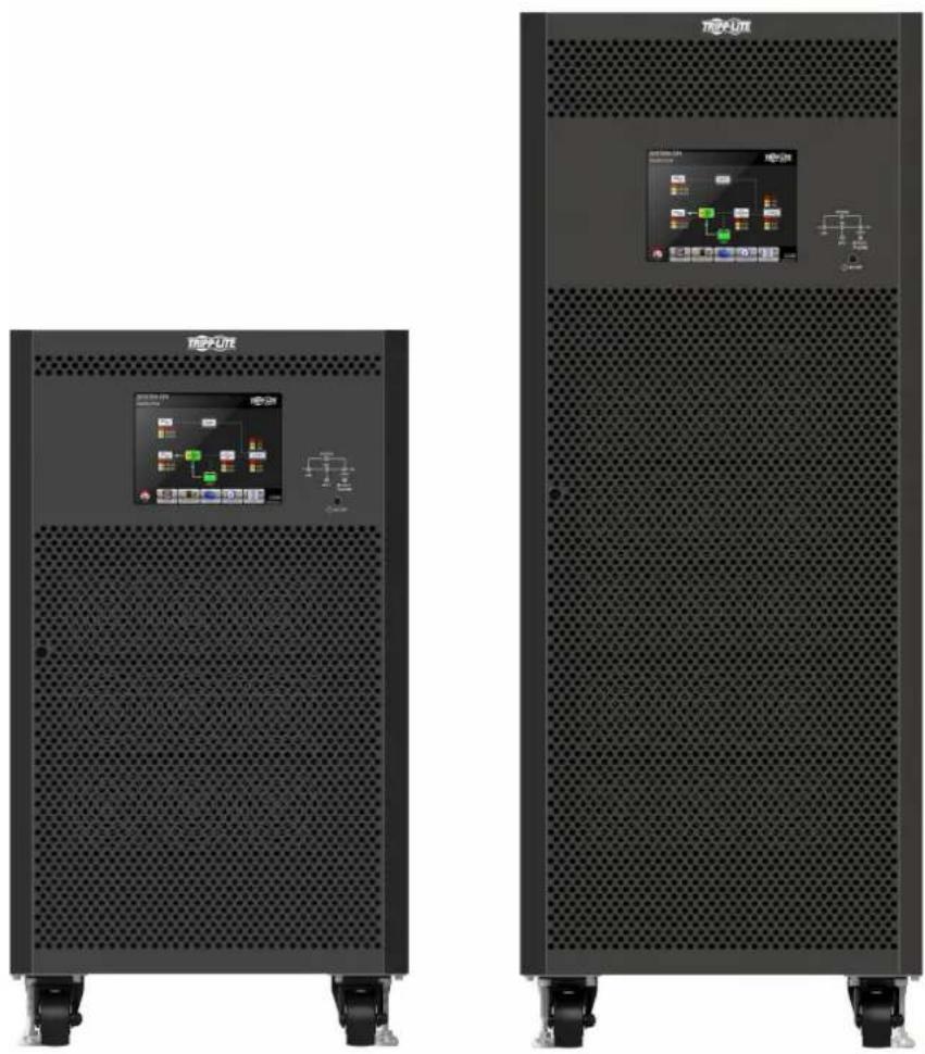


1111 W. 35th Street, Chicago, IL 60609 USA · tripnite.com/support
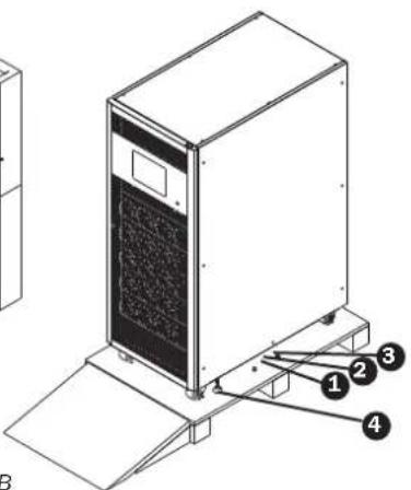
Figure 3.2B Figure 3.3B
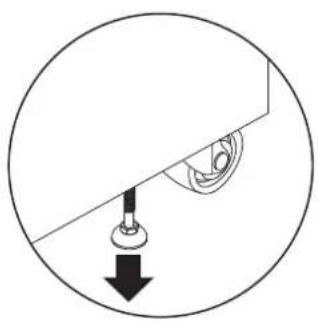
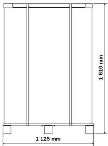

Figure 3.4B Figure 3.5B
3. Installation et configuration
6.2.5 Mode Derivation

12 V 65/100 Ah x 40 pieces 12 V 40 Ah x 40 pieces
1111 W. 35th Street, Chicago, IL 60609 USA • tripplite.com/support
Tpexфа3ныe ИБп cepи SmartOnline S3MX
Mодени: S3M100KX, S3M100KXD, S3M120KX, S3M120KXD, S3M160KX, S3M160KXD, S3M200KX, S3M200KXD
BxOJHoe nHTaHHe: 220/230/240 B (Φ.-H.), 380/400/415 B (Φ.-Φ.), 3-Φa3Hoe, 4 npoBoa + 33
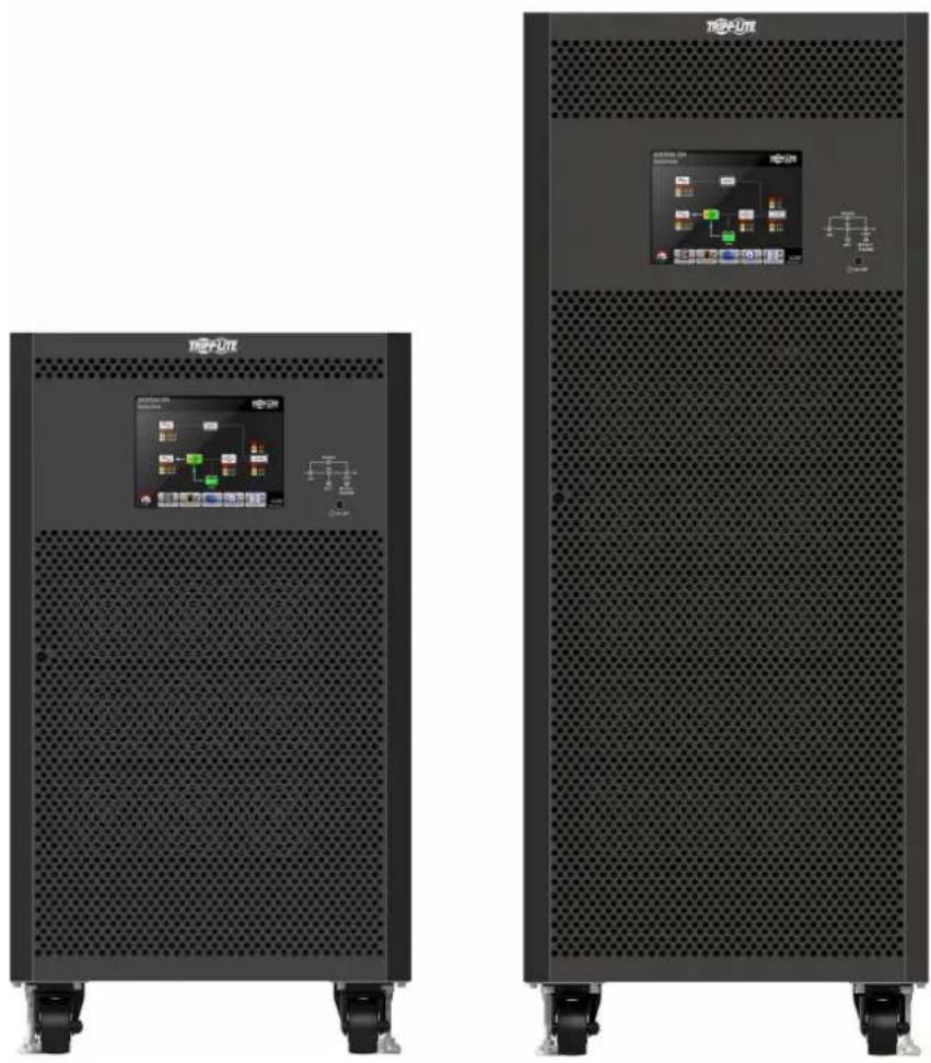


PryyBmR BcHnrs KBCF370A
CopepkHne
1. BBeDHeN 214
2. Baxhble npedynpekdeHn no Texnke 6e3onachoctn 215
2.1 Pnpynpexkndnna OTHoCHTbNo MeTa pa3MeueHn N5P 215
2.2 PpeynpckdeneoTHocntenbHO noKnIOeHnO6OpydoBaHa 215
2.3 PpeynpexdHnOTHoCHTeBHO6aTapei 215
2.4 TpAnCnpTIpOBKa HxpaHeHne 216
2.5 IoproToBka 216
2.6 YctaHOBka 216
2.7 PnpynpexdHnO tHocntbNo noknouehn 216
2.8 PoppokKcknnyataun 217
2.9 CoOTBcTCTBmC tAndaptam 217
3.YctaHObKa HnacTpoiKa 218
3.1.PacnaKOBka NOCMOTp 218
3.2.BWDcOTKpbTToI nepeDneHnaneHb2 220
3.2.1 WntepfeiChbIe N KOMMyHuaKaiUOHbIe 3JIeMeHTbl 221
3.2.2 CnnoBoi KaKaI/MoDyIb 221
3.3 3eMeHTb3aDHeN naHEn 222
3.4 Bnblco cToPOhbl MoHTaXhblx 3aXHMOB 223
3.5 YctaHOBKa OdINHOuHOrO IVI 224
3.6 YctahOBKa IVB B CNTeMax c npaJIeIbHbIM NOKJIHOeHHem 226
3.6.1BxOHaN BbIXoHaN npOBKa 226
3.6.2 Hacroka nata npaannelno noKluuhen 228
3.6.3 HacpoKa ha paaboTy B pekIme npaapanenbHoro noKnUoyehn 230
3.6.4IapalJIeBHOe noKIOUeHne Ka6eJe 230
3.6.5IopraDOKBKNIOUeHnCINCTeMbICnapaIIeHBbIM 231 noKnIOUeHnEMIBI
3.7 YCTAHOBKa CO CDBOeHHbIM BXoDM IITaHINI INPeMeHHoro TOKa 231
Moden S3M100KX, S3M100KXD u S3M120KX, S3M120KXD
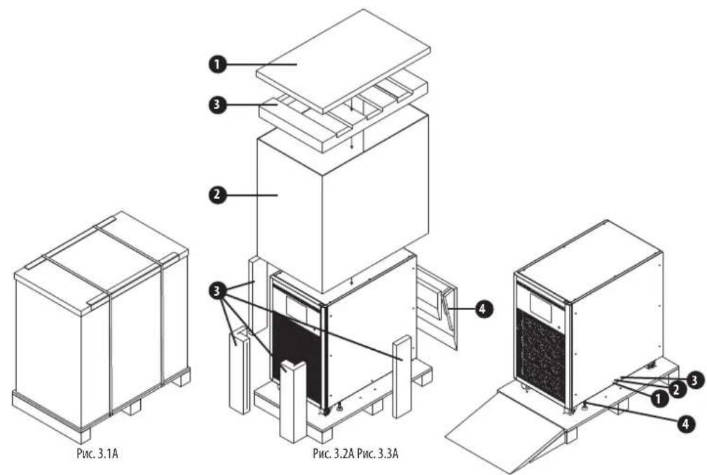
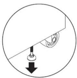
Puc.3.4A Puc.3.5A

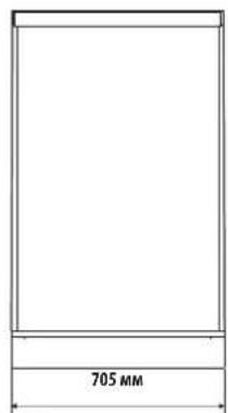
3.YctahOBka nHaCTpoiKa
Moden S3M160KX, S3M160KXD, u S3M200KX, S3M200KXD

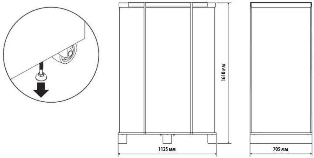
PUC.3.4B PUC.3.5B
3.YctaHOBka NHaCTpoiKa
BbHbTe ynakobky cKomnlektyoummu n npoebpe te e coepkmoe. B ctaHapthoTpaHcnpTnpOBOOHnyakobke donKhb haxoDutcb PykoBDCTBO noh3oBaTeaN Kabe RS-232.KnoUOT WpI npKpenneK nepedHe Dbepe C nomoiu kabeHo CTAAKK. Bynakobke taKke Moryt HaxoHTcRdoONHnTeHBie KOMnlektyounie N KomHOENTb IB 3aBNCMOCTOn KOHKpeTHoK Komnlektauin KInneHTcknx 3aKa3OB.
IpmeueHne. Iepa yctahOBKn H3dennn erc cneyertocmoptb. Y6eBteCb B otcyTCTBN h3ueecknx nobpekDn HycpOCTBa. He kmoaHTaeYcTPOCTBO.B Cnyae obhApkyenKaKHX-Nb6o NBpeXdEHN KNTOTCYTBQUHN Detane/ KOJIINNEKTOUHX HEMeDnHNO COoUeHTe 03Tom pncTabeTteno nepeBosWka Hnn Dnepy. CoxpaHIne 3abOckyynAkoKBy nI INCNIOB3OBAHN BdyuueM. KaKdb KOMOHEHT O6pyOBAHNI KOMNKeT 6atapEn peKOMHeYcTa XPAHnB T CBOE 3abOckOy yNAKOKE, NOCKOKNO HA paccHTHa Ha o6ceueHne MaKcmMaBHO 3auHTb BO BPEMTPAHNCNPTPOBNN XpAHENH
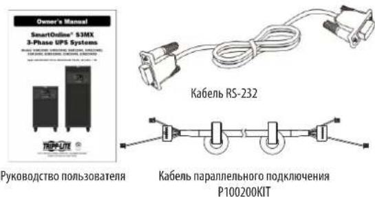
3.2 BnD cOTKpbITOn npepeHne naHeBIO
Kakdbn HbNocTabnTcB KOMnneKTe cKnouom O TpepeHdBepu. Knou npknpenn K nepeHdBepue c NmOoBIO KabenbHO CTaKKU. OTkpBnpeepHIO depuy, Bby BVnnte BHTPNkkaof KOMmyHkaunHbH oTEc NK HeCKOBKO CNOBbIX KAKdaob/Moyne. Y kaoDoro CNOBOrO KACKaDA/MoyyI MMeTcR Xopo0o 3AmTHbI NeHTnKAtop.
Ta6nua 3.1 NdeHTnHkaaun CnnoBbIX KacKaIOB
3.4 BnDblcoCTopoHbIMOHTaXhbIX 3aXHMOB
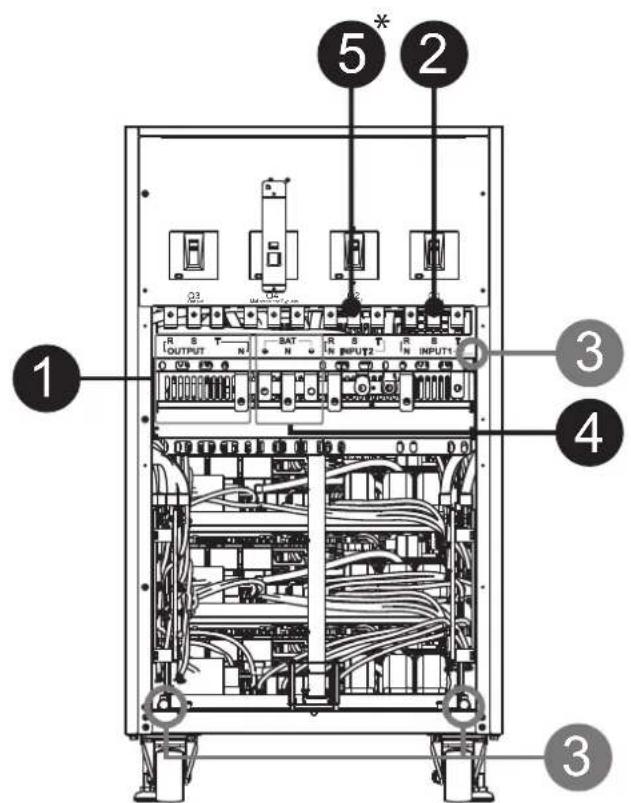
100 KBA / 120 KBA
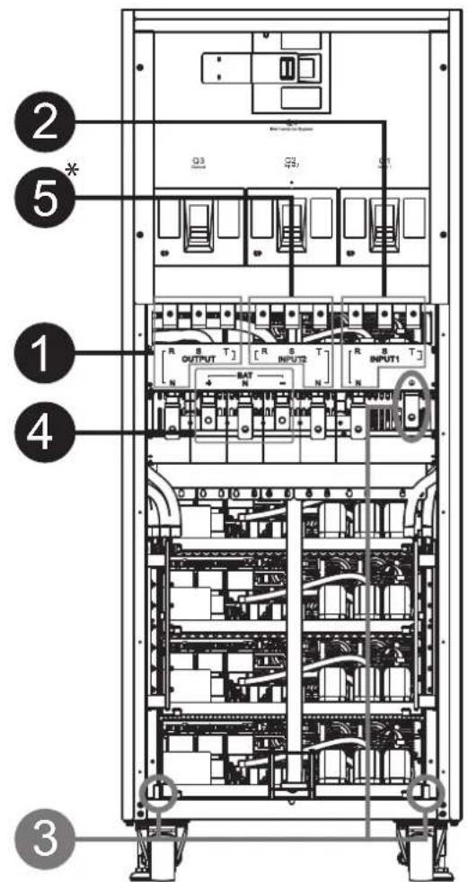
160 KBA/200 KBA
Y6eHntecb TOM, YTOB DAHHBI MOMeHT HN Ha OIN N3 IVI He NOaTeC 3NeKtpOnITAHNA.
Pocne npabnboHO BbnoHHeMa DBy Bx BbIeOnmCaHHbX DeCTBn N HactpoKo KOnHpypaum 6aTape nepexOJte K CndyoUcM DeEChTBnA
1.He noocnHnre KaebnapaennbHoro noKKnUeyHndo coOTBeTCTByuOero yka3Ha Ha 3KpaHe.
- YctahOBtBe BxOJHbE abTOMaTHueCKHe BblKIOuATeIN (Q1) 06oHX M5P B nOIOXeHne "ON" (BKJI).Y6eIITcB TOM, yTO BbIXOHDbe aBtOMaTHueCKHe BblKIOUaTeIN (Q3) 06oHX M5P HaxoJrTaB nOIOXeHn "OFF" (BblKI).
3.IpebeDHTe ABToMaTHueCKn BbIKJIOaTeNb 6aTapeN B noJoxKeHne "ON"(BKJI). - IpebeBnTe BbKIOaTeIb BHeHrero HcToHmKa nepeMeHHoro ToKa B nOIOKeHne "ON" (BKJI) nIra nOauHnITAHHa ha 06a N5N.
5.Doxntecb noHoro BKJIOHnme HOBX uCTPOINCTB.NepexoTe K nactpoKe IV5I1. - HacpoBte paboty B npaJIbIbHom pexHme Ha KxNanEn I5I 1. BoiInTe B MeHIO "PARALLE" ("PAPJIeIbHOE IIOKIIIOUHENE") Ha ctpaHne "SETUP"(HAHApIbHAR YCTAHOBKA") (6oee noipobhna HOpmaun npedctabnHa B paDe 4.2.5 3Kpah "HauaIbHa YtAHOBKa — Papanenbhoe npoknouHe).
- BkIIOHTe cyHxuOUPS Parallel"("PapJIenbHoe noKIOUeHne N5Pi") N5Pi 1 (npdynpeXeHne "Parallel UPS Cable Loose" ("HennoTHbIKoTAKT Ka6eNpaIINbHoro noKnIOUeHn N5Pi") cndyET npOHOpOpOBaTB).
- BbIepeTe npednoTneBHyIO nlaCe6aKoHpyaunO batapei:"independent"(He3aBcMma)INn"common"(O6bHna).
9.Ди coханенс CBONH hactpoek haxmite Ha 3aouok "Save Setting"(CoxpaHt b HacptoiKn)Ha kpahe "General"(O6uue HacptoiKn)CTpaHnbl"SETUP"(HAYAHLBA YCTAHOBKA"). - NepexoJnte KnaCTpOKe N5P 2.
- NaCTPOIte pa60by b npaJIeHbOM pexmHe na XK-naneHn I5I 2. BoJInTe B meHIO PARALLEL" ("NAPALJIeHbHOE NOKIIOYEHNE") Ha cTpaHne "SETUP" ("HAUYANbHAR YCTAHOBKA") (6oJIee noPpO6Ha HnΦOpMaun npedctabHeA b pa3dene 4.2.5.5 3Kpaan "HaayAbHra yCTahOBKa — NapannenbHoe noKnIOueHne").
- BkHouHe cyHKUO"UPS Parallel"(PapalnBhoe noKJIOueHne N5Pi) N5Pi 1 (npedynpeXdHne "Parallel UPS Cable Loose"(HennoTHbIKoHTaKT Ka6ena npaIJIenbHoro nokKnouHnN5Pi") cneyet npOHrOpHpOBat).
- Bb6peHne npednoHTeBHyIOIe 6e8 KOHpyrauio 6aapei:"independent"(He3ABmHa) mui "common"(O6bHna).
14.ДлcaoxpaHnHcBmH NaCTpoeK HAKMITE Ha3aOoK"Save Setting"(CoxpaHnHb HacTpoiKn)Ha Kpahe"General"(06uue NaHcTpoiKn)ctpaHnIb"SETUP"(HAHAlbHAR YCTAHOBKA"). - IpebeJeTe ATOmatMueckn BbIKIOuAteIb BHeHrero NcToOHNkA nepeMeHHOrO ToKa B NoIOXeHne "OFF" (BbIKI) MdoJNTeCb NIoHOro BbIKIOUeHn O6mX IVI.
16.песьдente abTomatmueckne bblknuaytei nbaapeB noIonoJeHne "OFF"(BblKI).
3.6.4 NapalnebHoe npKIOUeHne Ka6eIe
HaKoHcKaJdOrO Ka6EbnapaIeHnOIOKJIoueHmHMeOTc TpNpa3bema,OINH NKTOKOpbIX ABnETc16-KoHTAKThbIM,aDBApyTHx-2-KoHTAKThbIM.
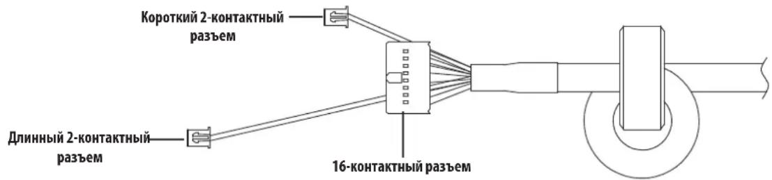
Приимechanical:
IINbI moen 100K n 120K cnoH noaonnapnneBho n oKnOueHHN e 16-KoHTA h bpa3eM N KopoTkn 2-KoHTA h bpa3eM.
IIN61 moen 160K 200K c Dmy napamn npaennbHoro nocknueHHra: noocoeHHte 16-koHTAeHHpa3bem H KopoTkn 2-KoHTAKTHb pa3bem K HxHne pnaTe.3aTe mnoCoedHHTe nnHHb 2-KoHTAeTHb pa3bem K BepxHne pnaTe.
Ipn cyuahom ocoeMHmH 2-koTHaTHoro pa3bema IV5Bbdaet ouh6y:Warning! Parallel UPS Cable Loose"(BHMMHHe HEnnoTHbIKoHTAKKabeNapannelbHO NOOKIOHnueIVI).BCTabte 16-koTHaTHbpa3bem B nHE3do CN7, a 2-KoTHaTHbpa3bem -B nHE3do CN10 natab npanenbHorO noKnIOHnueIVI. BCTabte BTOPO KOncE npanenbHorO noKnIOHnueB pntaty npannelbHorO noKnIOHnueIVI 2 n ananorHbM ibp3oM CTabbe 16-koTHaTHb pa3bem B nHE3do CN7, a 2-KoTHaTHb pa3bem -B nHE3do CN10.
Pnc.3.10 Pnata npannenbHoro noKnouhen H51 Pnc.3.11 Pnata npannenbHoro noKnouhen H51 Pnc
3.YctaHOBKa nHaCTpoiKa

BHHMaHHe!
Hnpabnha pa3bka ka6ene npannelbHoro noKnouhen npBeet K hapuene HOpMaBHO pa6otbl. IpobepaTe npabnboctb kaidoro dectbn npnoedneHH Ka6ene npannelbHoro noKnouehn KKaKdomyIbI.
Y6eHNTecb B TOM, YTOB DAHHBIMOMENT HN HA OINH N5I He nOdaTc3 NeKtponrTaHn.
3.6.5 NopaoK BkIooHn CNTembl napanJIeNbHbIM IOKIOueHnEM IVI
1.y6eHntecbBnpaunbHOCTM BblnoJIHeHHaYyka3AHm,IM3NOKeHHbIX pa3dennax 3.6.1-3.6.4.
2.Y6eHITcB B TOM, YTO BXOHOH BbIKIOHATen H bIXOHNbE BbIKIOHATEKAKDOrO N5Pi nepeBeDeHb B noJooHeH "ON"(BKJI).
3.пегеведente abTomatmeckи bblknnoateNBaatapeN b noJIOKeHne"ON"(BKN).
4. IpebeJeHte BbKIOuTeJIb BHeUHero HcTOUHka IpeMeHHoro ToKa B NIOJOKeHHe "ON"(BKJ)IINaIPOaHnHTAHHa 06a N5N.
5. CnneIte 3a coo6ueHmIM O hapuueHHx HopmaJIbHOJ paOTo bHa JK-dmcIIee (60lee noDpO6Hn HnHOFMaun npEcdTbnHe B pa3Je 4.2.7KpaH co6bTm.
6. BkIIOHTe IbI HauKHeM KhoNKe Ha erO IueBcHn NaHEn Nm Upe3 cTpaHnU ynpabHeHn Ha XK-naHn (6oone noDpo6Ha nHΦopMaua npedctabHeBa paDeJe 4.2.3 3KpAn npapabHeHn).
3.7 YctahOBKa CO cDBoeHHbIM BXoIDOM NITaHnI nepeMeHHoro TOKa
MoJIeH N5Ic o CBOEHHbIM BXoDM mTAHnHnpeMeEHORo TOKa (oO3NaueHnKOTopbIX cOpEgKAT cyphiKc"KXD") npBueHeBk K6a3OB0 KoHpyaunm COnHapbHM BXoDM nTAHnnepeMeEHORo TOKa nocpeCTBOM yCTAHOBKN Tpex 3akopaUmbauux npembueK Mekdy BXoDM npemeHHoro ToKa 1 (AC Input 1) uBXoDM npemeHHoro ToKa 2 (AC Input 2).Pnp JxenaHnncIOJIb3OBAbMoJIn "KXD" co CBOEHHbIM BXoDM npemeHHoro ToKa Heo6XoDMn CHaTb 3TN TPN npembuiuN BblONHITb pa3BOKy BXoDA npemeHHoro ToKa 1 IN BXOda npemeHHoro ToKa 2 COOTBETCTBYUUM 6pa3OM.
IpeembukmBoMoJenX"KXD"coCboeHHbIMBXoDMpeMeHHoroToka.
KoCHNTcB KONIKI Dn BxOaB NoDMeHIO Measurment (M3MepeHne).B TOM NoDMeHIO MOKHO Bb6paTb NIObyu H3 OOni (Input/BxOaD, Output/BbxOaD, Bypass/06xOHaA ueB, Load/ Harpy3ka Hn Battery/Batape) dna nOtuYenHn noPb6Hn HNOOPMaun o CTayce COOTBETCTBYouero 3eMAEHTa CNTEMbl. cm. pnc.4.8 u 4.9.
Puc.4.8 MeHIO Measurement (N3mpeHne)
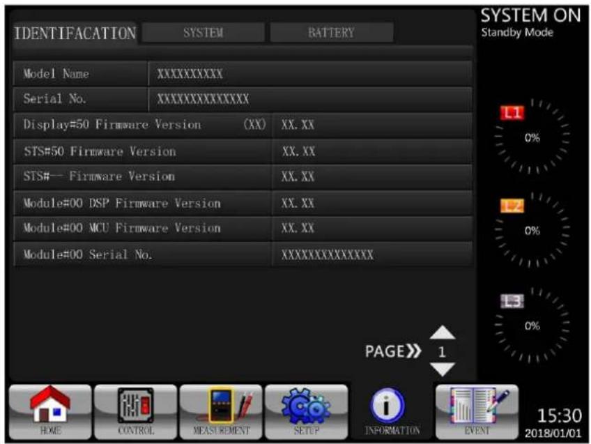
Pnc.4.22 CtpaHnua 3KpaHa lndfication (NdeHTnFkAauHbne npametpb)
4.2.6.2 3KpaH INFORMATION - System (HHOPMAUHA — Cnctema)
PnBbOpe noMeHO System (CnCTema) Ha nncnne BbBOIDTCa TAKA HOpMaZRA KAK MOHOCb CnCTembl, HOMHaIbHOe HApJXeHHe, HOMHaIbHAn Yactota m dp. Iner nepexoda MeKdy cTpaHcAmn NOnb3yTeCB CTpeKamN BBEPX HBN3.
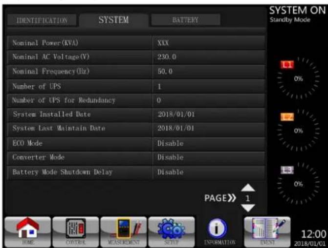
PmC.4.23 CtpaHua 1KpaHa INFORMA Tion - System (MHOPMALIA-Cntema)
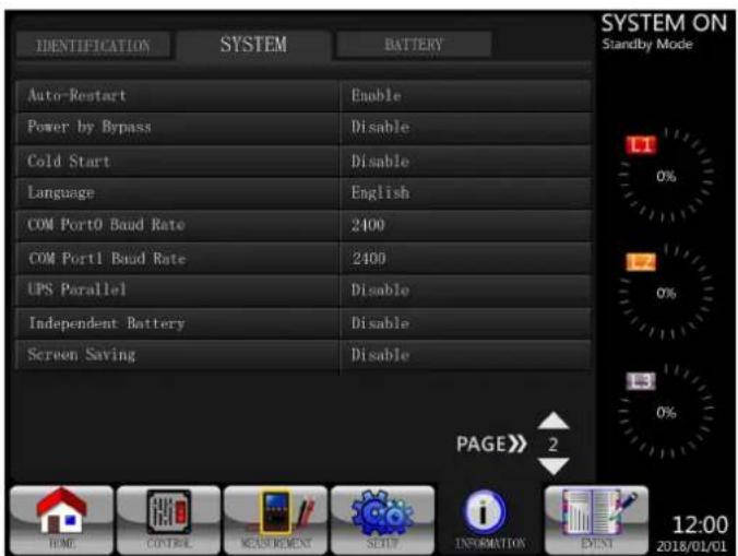
PmC.4.24 CtpaHua 2 Ekapha INFORMATION - System (MHOPMALHA - Cntema)
6.2.6 Pekm ECMO (3KoHOMuHbI)
PekmE ECO moKET BkIIOUaTbcape3 naneHb npAbeHnHa KK-dcnnee. B pexmE ECO notpe6nten nepeKIOaOTc ha 0xOHyu cIe npy uCNOBm, yTO ee hapJaeHe H aCTota haoTcB doynctTMOM dnaana3oE. Ecm HapJaeHeHne 0xOHOH cIe H bIXoJIT 3a rpaHmUpDOnyCTMIMO dnaana3oHa, to IVPi nepeKIOaET NCTOHN MNTAHNA C 0xOHOH cIeHn Ha npoe6p3oBaTeB. Ida cokpaueHn BpeMeHn TAKORo pekeKIOUeHn Pn pa6ote IVPi B pexmE ECO bInpamnteln nppe6p3oBaTeB fynHKUHOHPYOT NOCTOAHHO.
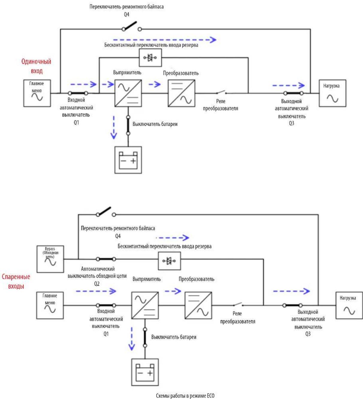
6.Приицпы paбовы
6.2.7 PeknM OTKIOUeHHN
PbBkyKnHueHHN 16nOyCTBnCteBOrO nctOuyHnKa nTahnA H5npepOoHT B pexmOtKNoHcHnA.
Ecn cTeBo HcTOnHn nHTAHn OTCyTCTByet, a NpN mChepnAn 3Heprn6 batae I do ypoBn OteCkN, cooTBcTbYIOero 10 B ha KaKdyio 6batae npri TeMnpaType 25^, to Np TaKe npexoDn B pekm OTKIOueHn.
Bcnyae nepexoHa IBn B 3OT pekim OH otknioaet ynpablaooee Hapjace He NbH bblpmaTeIa, a TaKke BkIOaet 3apdHoe ycpoICTBO n npoe6pa0BaTeIb.
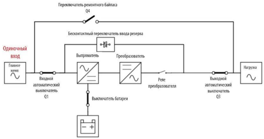
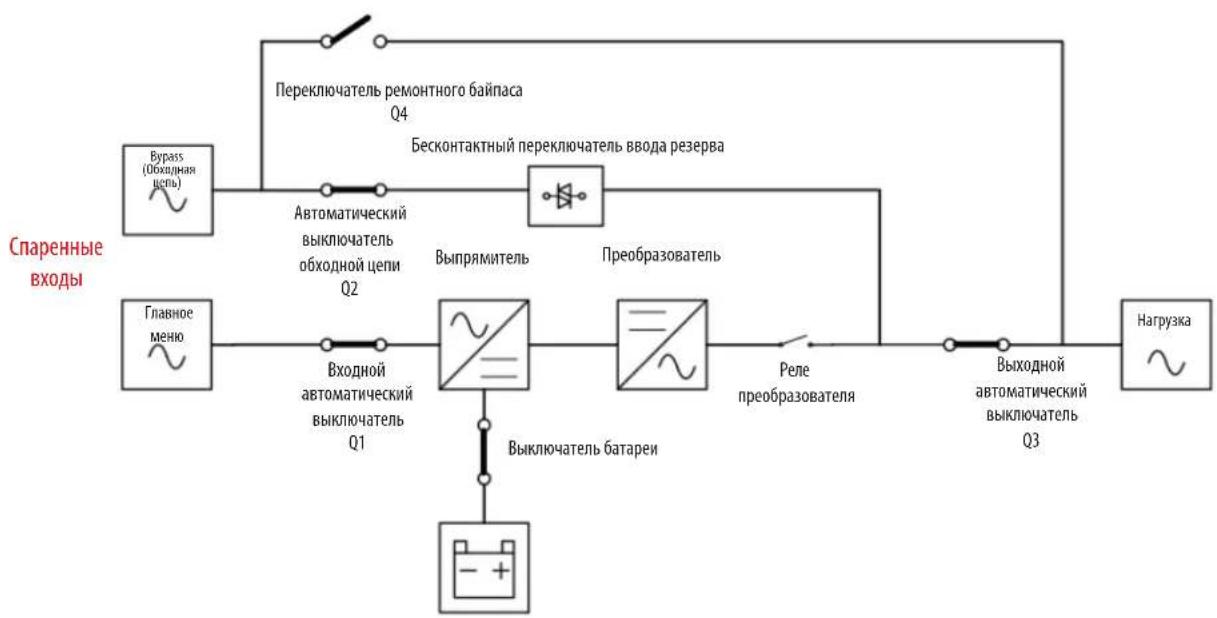
CEmbIpa0bTbBpeKImeOtKnloueHn
6.Приицпы paбовы
6.2.8 Pekum pemohthoro 6ainaca
UcTbO OCHaTaCpUHbIM NepeKIOuATEMeHa 06xOHyUeNb dIa ObceueHnE 6bcpeBooHoi NpaDn HTHAHKn KpnTuCKBaxHbIM nTopeBteMaB E Tx cyuaay, KOrDa OCHOBHe yHKuHm IBIT CTAHOBTCA HeoCTyHbIM (HapPMep, BO BPEM TExHueckoro 06cyuHBnHA).Peep nepeKIOuHem B pexHM peMOHTHO baiNa cHa eHo6xOHNMo y6eNTbCBA DocTyHNOCTNtOuyHMA nHTAHNA 06xOHN UeHN.
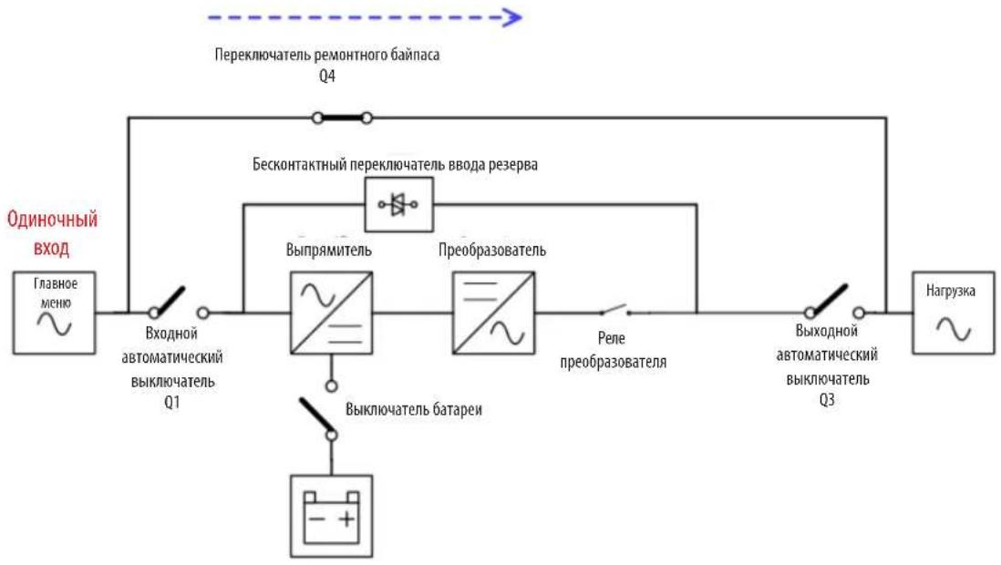
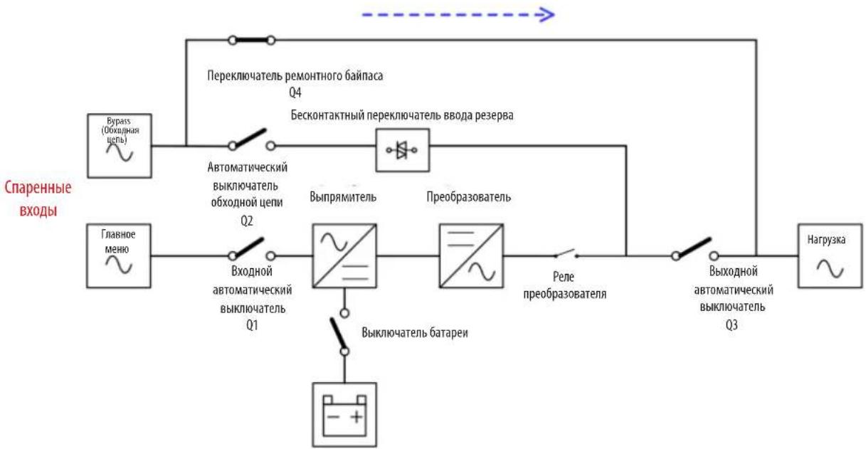
Cxemblpa60tbBpekmmepeMOHTHOro6aInaca
7.Зкпnyataцnia NBП

BHIMAHHE!
- He 3aynckaiTe M6Pi do 3abepeHnna npoecca eero yctanOBKn.
-86eDnTcB nPabunbHocTH npKnIouehn 3NeKtpnpoBOKn npOpoHocTH oKcaHn cnNoBbIX kaBeen. - Y6eHntecb B npabInbHocTHn HacptpOKn aDpecoB CNoBbIX KackaNoB. Pndpo6Hee cm. B pa3dene 3.3 n Ta6nue 3.1.
- Y6eDHTecb TOM, YTO BCE ABToMaTHUcKHe BbIKNIOuATEHn HaxoJITcB NnoJooKeHHN OFF (BbIKJI).
7.1 3anyck B pexkme nHTaHn oT ceTu nepeMeHHoro ToKa
PnBkNoHcHmNbMnNoHcTbNo"06eToeHHo"coCToAHmNcNoMb3yTeaCneDyUaA npOeDpya.
- PaoTaB cTeBoe nTahHe Ha VbI.
War 2. PpeBecn BbIKIOaTeNb 6aTapeN (BHeHero 6aTapeHoro IkaFa) B noIooKeHne ON (BKJI).
- IpebeCTn BxOdoHn ABToMaTHueckn BbIKIOuTeNb (Q1)B noJooJeHne ON (BKJI).
Ira moen co cnapenHbim BxOIOM: npepeBcTN BxOHOH ABToMaTHueckn BbIKIOuATEnb (Q1) nABToMaTHueckn BbIKIOuATEnb o6xoHNO CEIN (Q2) BnoIOKeHe "ON" ("BKII").
I 4. BbKdab 0nHy Mmhy. Ha KK-dncnnee oTo6paKaeta HmOpMaun, npedctaneeHna Hnke. IBp nepeoxuB pekmm pa6to b no 6xohnoe, eon 3oT pekm pa3pewe (daHHa HacptoKa yCTahOBnHa no ymonauHIO). Ecm pekm pa6to b no 6xohnoe cen n3anpeuen, to IBn octaTcB pekmme Standby (OxmaHne).
7.Зкпnyataцnia NBП
I 5. y6eHbTcB OTCyTCTBn npeynpeckdenn mnn 3aФmKcnpoabaHbix cobttn OK3a. Pnp HauuNN KAKORO-lno ppeynpeckdnn nnn cobttn OK3a cneYET nnonbTaBC peumtb BoHHKny npo6nemy B COOTBeTCTBn Cpa3denom 8. BbIaBHeNe H yctpAneHne HeKnPabHocTei.
War 6. NpepeBcTb BixoHOn ABToMaTHueCKn BbKIOaTeNb (Q3) B nIonoJKeHne ON (BKJI).

Khonka "Power On/Off"
MoeJx S3M100KX/S3M100KXD S3M120KX/S3M120KXD (100kBA/120kVA)
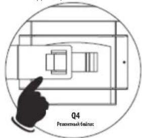
MoenX53M160KX/S3M160KXD S3M200KX/S3M200KXD (160 KBA/200kVA)
War 2Y6eHHTbC B TOM, yTO I5I ΦyHKUONHpyET B pexMe pa60tbo no 6xOHOH cENM.
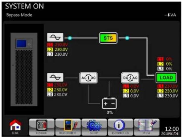
War3pepebctnpeknoatentb pemonthoro 6ainaca 04 b noonoxene "ON"/"BKJ"(dna Bcex moenei).
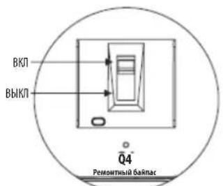
MoeJax S3M100KX/S3M100KXD S3M120KX/S3M120KXD (100kBA/120kBA)
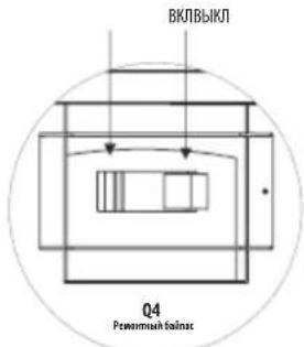
MoeJax S3M160KX/S3M160KXD S3M200KX/S3M200KXD (160 kBA/200 kBA)
7.Зкпnyataцnia NBП
Uar 3. IpepeBcTn BxOHN aBToMaTHueCKM bByKIOuATEb Q1 BnonOKeHne "OFF" (BbIKJ).
Ima moen Co cnapenHbim BxOom: nepeBecTn BxOHO ABToMaTHueckn BblIOHateNB (Q1) n AToMaTHueckn BblIOHouTeNB 06xOHOH CEIN (Q2) B noLoJeHe "OFF"(BBKJI).
W4.BpeKmme OTKIOUeHnIbI NOCTeNEHNO oEoctOuBaETc. DoXaTaBcO TkIOUeHnI Kx-IMCnne.
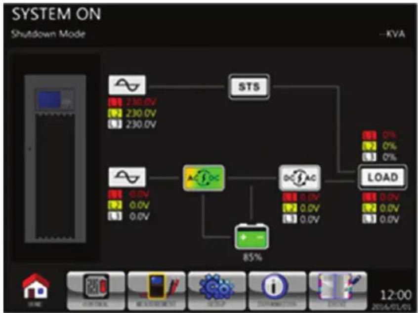
War 5. Nocne otKIOUeHnM IVIeNpeBedeTbe BIKIOuHTeNBHEHrO IITAHMa B NOIOXHeHne OFF (BbIK) dIra OTOeDINHMe IISIOT HcOTyHnKa IITAHMa NpeMeHHORo ToKA.
War 6. Ecn NbIb ydt OT KIOHueh OT NCTOCHKA NHTAHNA NEPEMeHHORo TOKa HA DNIITeNBHO BpEMr, TO CNEyET NepeBecT NBIKIOUaTeNB 6aTapei (BHeuHero 6aTapeHoro Ika) B noJooXeHne OFF (Bblk).
8. BbIaBHeHne n yctpaHHeHne HncnpaBHOCTe
PObepka OTKa3OB IN ppeynpexdHn DOnJHn PPOIN3BOuNTbCBy yNtOHMOUeHHbIM CepBnCHbIM nepcoHaONOM.
| Coobuchene na Jęk-dinclnepe Pa3b3c3nene Meocb yctrahenne | |||
| Fault! Bus Over Voltage Слишков Велиcodе на симпостаху на симпостаху на симпostаху на симпostаху на симпostаху на симпostаху на симпostаху на симпostаху на симпostаху на симпostаху на симпostаху на симпostаху на симпostаху на симпostаху на симпostаху oncochondrofa. 06patitec b k cepbrichomny nepceohany. | |||
| Fault! Bus Under Voltage Слишков Н��codе насшалду на симпостаху на симпostаху на симпostаху на симпostаху на симпostаху oncochondrofa. 06patitec b k cepbrichomny nepceohany. | |||
| Fault! Bus Voltage Unbalance Haprajekene Na lihne noctoanhhoro Toke He cboaHnHoro Toke He cboaHnHoro Toke. 06patitec b k cepbrichomny nepceohany. | |||
| Fault! Bus Short Kopotkoze zambyakane ushno mbocorpo. 06patitec b k cepbrichomny nepceohany. | |||
| Fault! Bus Soft Start Time Out 3aunck blypmaitener Nebozmojenen H3-3a H3K00r npaRajpeHnHoro Na 0uHne noctoanhhoro Toke TceHne 3adahnhoro Bvemehn. | Быкочite МБПи з苹устен erо посторно. Пглп посторном отkaaze epobatitec b K cepbrichomny nepceohany. | ||
| Fault! Inverter Soft Start Time Out Haprajekene pree Opa3ozabatey nhe dcstnlaeet jxenaemoro 3nauchenry B Teuehme 3adahnhoro Bvemehn. | Быкочite МБПи з苹устен erо посторно. Пглп посторном oztakae epobatitec b K cepbrichomny nepceohany. | ||
| Fault! Inverter Voltage Over Haprajekene npoeobop3ozabotare Na preeblyaet npoeiBelhoe 3nauchenry. | Быкочite МБПи з苹устен erо посторно. Пглп посторном oztakae epobatitec b K cepbrichomny nepceohany. | ||
| Fault! Inverter Voltage High Cnizikom Mblcokoe Naprajekene npoeobop3ozabotare. | Быкочite МБПи з苹устен erо посторно. Пглп посторном oztakae epobatitec b K cepbrichomny nepceohany. | ||
| Fault! Inverter Voltage Low Cnizikom Nl3K0e Naprajekene npoeobop3ozabotare. | Быкочite МБПи з苹устен erо посторно. Пглп посторном oztakae epobatitec b K cepbrichomny nepceohany. | ||
| Fault! R Inverter Voltage Short Kapotkoze zambyakane Pha3b R Na blyxoedne preeobop3ozabotare. | Быкочite МБПи з苹устен erо посторно. Пглп посторном oztakae epobatitec b K cepbrichomny nepceohany. | ||
| Fault! S Inverter Voltage Short Kapotkoze zambyakane Pha3b S Na blyxoedne preeobop3ozabotare. | Быкочite МБПи з苹устен erо посторно. Пглп посторном oztakae epobatitec b K cepbrichomny nepceohany. | ||
| Fault! T Inverter Voltage Short Kapotkoze zambyakane Pha3b T Na blyxoedne preeobop3ozabotare. | Быкочite МБПи з苹устен erо посторно. Пглп посторном oztakae epobatitec b K cepbrichomny nepceohany. | ||
| Fault! RS Inverter Voltage Short Kapotkoze zambyakane Pha3 R-S Na blyxoedne preeobop3ozabotare. | Быкочite МБПи з苹устен erо посторно. Пглп посторном oztakae epobatitec b K cepbrichomny nepceohany. | ||
| Fault! ST Inverter Voltage Short Kapotkoze zambyakane Pha3 S Na blyxoedne preeobop3ozabotare. | Быкочite МБПи з苹устен erо посторно. Пглп посторном oztakae epobatitec b K cepbrichomny nepceohany. | ||
| Fault! TR Inverter Voltage Short Kapotkoze zambyakane Pha3 T-R Na blyxoedne preeobop3ozabotare. | Быкочite МБПи з苹устен erо посторно. Пглп посторном oztakae epobatitec b K cepbrichomny nepceohany. | ||
| Fault! Inverter R Negative Power Kapotkoze npoeobop3ozabotare. | Быкочite МБПи з苹устен erо посторно. Пглп посторном ouzhoctm no 0a3e Ra Na blyxoedne preeobop3ozabotare. | ||
| Fault! Inverter S Negative Power Kapotkoze npoeobop3ozabotare. | Быкочite МБПи з苹устен erо посторно. Пглп посторном ouzhoctm no 0a3e Ra Na blyxoedne preeobop3ozabotare. | ||
| Fault! T Negative Power Kapotb V naeBdoYCIMOnO 3nauchenry Oprua3d4tBnHnHnMoUOHTNIO 0a3e Ra Na blyxoedne preeobop3ozabotare. | Быкочite MCB K cepbrichomny nepceohany. | ||
| Fault! Over Load Fault Otsa3 I5I13-3a 3nauchetntbHnHneperegrpy3kn. | УменьшITE Na rhyz. | ||
| Fault! Battery Fault Hapuyeshne noJoparHnToPri niPojdKluoyenHnBatapei. | Поверъte пог�ность рогдкунчесь варотерь и obpatitec b K cepbrichomny nepceohany. | ||
| Fault! Over Temperature U6beDITb B naiHnMnDcTaoTuHoro npocrtanctBa DЯцркулдз in 803duXa i n cnpaRbHnHnO Bov3duXa i n cnpaRbHnHnO 603duXa i n cnpaRbHnHnO 603duXa i n cnpaRbHnHnO 603duXa i n cnpaRbHnHnO 603duXa i n cnpaRbHnHnO 603duXa i n cnpaRbHnHnO 603duXa I n cnpaRbHnHnO 603duXa I n cnpaRbHnHnO 603duXa I n cnpaRbHnHnO 603duXa I n cnpaRbHnHnO 603duXa I n cnpaRbHnHnO 603duXa I n cnpaRIY3X. | |||
| Fault! CAN Fault Oubi6bKa pRni BzaiMDoeiCTBn C miiH ON CAN. | Оветсь К керсИСМOTупс�ану. | ||
| Fault! TRIGO Fault Hapuyeshne cimHxpoHnHaZaZCuNi NucKOBOrO CmIHANLA. | Оветсь К КерсИСМOTупс�ану. | ||
| Fault! Relay Fault HeiciprabHnCTb pele npoeobop3azobatare. | Оветсь К КерсИСМOTупс�ану. | ||
| Fault! Line SCR Fail Kapotkoze zambyakane Na chtype TINPcHSTOPHORO uCTPOCTBA DЯцркулдз in 803duXa i n cnpaRbHnHnO 603duXa i n cnpaRbHnHnO 603duXa i n cnpaRbHnHnO 603duXa i n cnpaRbHnHnO 603duXa i n cnpaRbHnHnO 603duXaNTOA. | |||
| Fault! EEPROM Fault Oubi6bKa B p6o6Te 3c7CII3X. | Оветсь К КерсИСМOTупс�ану. | ||
| Fault! Parallel Cable Loosen Fault HeppoiHnCnTakT Ka6eNa napalIeNBHOrO PodKluoyenHn IBI. | Поверъte, He otcoeDInHnCnT Ka6eNa napalIeNBHOrO PodKluoyenHn IBI. | ||
| Fault! DSP MCU Stop Communicate Hapuyeshne CBs3i C minkpOpoeeccorpHbM KOHTpOIpLepom CmIFpOBoW B6pOboTm CmIHANLOB. | Оветсь К КерсИСМOTупс�ану. | ||
| Fault! Bypass Temperature Fault Hapuyeshne TempePAtyrHnO reEzima M6bMa 6b6DnHnO 603duXa i n cnpaRbHnHnO 603duXa i n cnpaRbHnHnO 603duXa i n cnpaRbHnHnO 603duXa i n cnpaRbHnHnO 603duXa i n cnpaRbHnHnO | |||
| Fault! Bypass SCR Fault Hapuyeshne HopmaIeNBHOn P6o6Te 3c7CII3X. | Оветсь К КерсИСМOTупс�ану. | ||
| Warning! EPO Active Поверпьтpbazbem EPO. | В symуае hapuyeshne p6o6ToBФФФФФФФФФФФФФФФФФФФФФФФФФФФФФФФФФФФФФФФФФФФФФФФФФФФФФФФФФФФФФФФФФФФФФФФФФФФФФФФФФФФФФФФФФФФФФФФФФФФФΦФФФФФФФФФФФФФФФФФФФФФФФФФФФФФФФФФФФФФФФФФФФФФФФФФФФФФФФФФФФФФФФФФФФФФФФФФФФФФФФФФФФФФФФФФФФФФФФФФФФffФФФФФФФФФФФФФФФФФФФФФФФФФФФФФФФФФФФФФФФФФФФФФФФФФФФФФФФФФФФФФФФФФФФФФФФФФФФФФФФФФФФФФФФФФФФФФФФФФФФφФФФФФФФФФФФФФФФФФФФФФФФФФФФФФФФФФФФФФФФФФФФФФФФФФФФФФФФФФФФФФФФФФФФФФФФФФФФФФФФФФФФФФФФФФФФФФФФФФФФ. 警告! Over Load Fail Μтрбчтел NMБКДммммммммммммммммммммммммммммммммммммммммммммммммммммммммммммммммммммммммммммммммммммммммммммммммммммmмmмmмmмmмmмmмmмmмmмmмmмmмmмmмmмmмmмmмmмmмmмmмmмmмmмmмmмmмmмmмmмmмmмmмmмmмmmмmmмmmмmmмmmмmmмmmмmmmмmmmмmmmмmmmмmmmмmmmмmmmмmmmмmmmмmmmмmmmмmmmмmmmмmmmмmmmмmmmмmmmмmmmмmmmмmmmмmmmмmmmмmmmмmmmмmmmмmmmmmmmmmmmmmmmmmmmmmmmmmmmmmmmmmmmmmmmmmmmmmmmmmmmmmmmmmmmmmmmmmmmmmmmmmmmmmmmmmmmmmmmmmmmmmmmmmmmmmmmmmmmmmmmmmmmmmmmmmmmmmmmmmmmmmmmmmmmmmmmmmmmmmmmmmmmmmmmmmmmmmmmmmmmmmmmmmmmmmmmmmmmmmmmmmmmmmmmmmmm mmmmmmmmmmmmmmmmmmmmmmmmmmmmmmmmmmmmmmmmmmmmmmmmmmmmmmmmmmmmmmmmmmmmmmmmmmmmmmmmmmmmmmmmmmmmmmmmmmmmmmmmmmmmmmmmmmmmmmmmmmmmmmmmmmmmmmmmmmmmmmmmmmmmmmmmmmmmmmmmmmmmmmmmmmmmmmmmmmmmmmmmmmmmmmmmmmmmmmmmnmmmmmmmmmmmmmmmmmmmmmmmmmmmmmmmmmmmmmmmmmmmmmmmmmmmmmmmmmmmmmmmmmmmmmmmmmmmmmmmmmmmmmmmmmmmmmmmmmmmmmmmmmmmmmmmmmmmmmmmmmmmmmmmmmmmmmmmmmmmmmmmmmmmmmmmmmmmmmmmmmmmmmmmmmmmmmmmmmmmmmmmmmmmmmmmmmmmmmmmmnmmmmmmmmmmmmmmmmmmmmmmmmmmmmmmmmmmmmmmmmmmmmmmmmmmmmmmmmmmmmmmmmmmmmmmmmmmmmmmmmmmmmmmmmmmmmmmmmmmmmmmmmmmmmmmmmmmmmmmmmmmmmmmmmmmmmmmmmmmmmmmmmmmmmmmmmmmmmmmmmmmmmmmmmmmmmmmmmmmmmmmmmmmmmmmmmmmmmmmammmmmmmmmmmmmmmmmmmmmmmmmmmmmmmmmmmmmmmmmmmmmmmmmmmmmmmmmmmmmmmmmmmmmmmmmmmmmmmmmmmmmmmmmmmmmmmmmmmmmmmmmmmmmmmmmmmmmmmmmmmmmmmmmmmmmmmmmmmmmmmmmmmmmmmmmmmmmmmmmmmmmmmmmmmmmmmmmmmmmmmmmmmmmmmmmmmmmmmmemmmmmmmmmmmmmmmmmmmmmmmmmmmmmmmmmmmmmmmmmmmmmmmmmmmmmmmmmmmmmmmmmmmmmmmmmmmmmmmmmmmmmmmmmmmmmmmmmmmmmmmmmmmmmmmmmmmmmmmmmmmmmmmmmmmmmmmmmmmmmmmmmmmmmmmmmmmmmmmmmmmmmmmmmmmmmmmmmmmmmmmmmmmmmmmmmmmmmmmmimmmmmmmmmmmmmmmmmmmmmmmmmmmmmmmmmmmmmmmmmmmmmmmmmmmmmmmmmmmmmmmmmmmmmmmmmmmmmmmmmmmmmmmmmmmmmmmmmmmmmmmmmmmmmmmmmmmmmmmmmmmmmmmmmmmmmmmmmmmmmmmmmmmmmmmmmmmmmmmmmmmmmmmmmmmmmmmmmmmmmmmmmmmmmmmmmmmmmmmmmmmmmmmmmmmmmmmmmmmmmmmmmmmmmmmmmmmmmmmmmmmmmmmmmmmmmmmmmmmmmmmmmmmmmmmmmmmmmmmmmmmmmmmmmmmmmmmmmmmmmmmmmmmmmmmmmmmmmmmmmmmmmmmmmmmmmmmmmmmmmmmmmmmmmmmmmmmmmmmmmmmmmmmmmmmmmmmmmmmmmmmmmmmmmmmmmmmmmmmmmzzzzzzzzzzzzzzzzzzzzzzzzzzzzzzzzzzzzzzzzzzzzzzzzzzzzzzzzzzzzzzzzzzzzzzzzzzzzzzzzzzzzzzzzzzzzzzzzzzzzzzzzzzzzzzzzzzzzzzzzzzzzzzzzzzzzzzzzzzzzzzzzzzzzzzzzzzzzzzzzzzzzzzzzzzzzzzzzzzzzzzzzzzzzzzzzzzzzzzzzZZzzzzzzzzzzzzzzzzzzzzzzzzzzzzzzzzzzzzzzzzzzzzzzzzzzzzzzzzzzzzzzzzzzzzzzzzzzzzzzzzzzzzzzzzzzzzzzzzzzzzzzzzzzzzzzzzzzzzzzzzzzzzzzzzzzzzzzzzzzzzzzzzzzzzzzzzzzzzzzzzzzzzzzzzzzzzzzzzzzzzzzzzzzzzzzzzzzzzzz. 警告! Over Load Failure Hapuyeshne npoeobop3ozabotare. | ||
8. BbIaBHeHne uYcTpaHHeHHe HncnPaBHOCTe
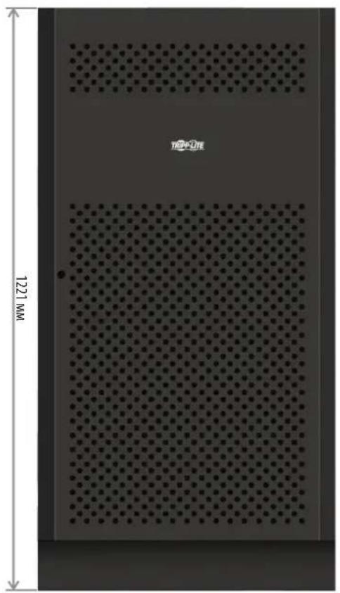
12B,65/100A·u×40wT.12B,40A·u×40wT.
| Моданы ваткфов Вьковачtenь в симплесе | Бабаринные размени (В x Ш x Г) ММОпсане | |
| BP480V100 | 400 A, 3-нолочны | 1501 x 826 x 1136 |
| BP480V100-NIB | ||
| BP480V65 | 300 A, 3-нолочны | |
| BP480V65-NIB | ||
| BP480V40 | 200 A, 3-нолочны 1220 x | 626 x 900 |
| BP480V40-NIB |

1111 W. 35th Street, Chicago, IL 60609 USA - triplite.com/support
Bedienungsanleitung
Modelle: S3M100KX, S3M100KXD, S3M120KX, S3M120KXD, S3M160KX, S3M160KXD, S3M200KX, S3M200KXD