PDU3XVN10G16 - Power strip Tripp Lite - Free user manual and instructions
Find the device manual for free PDU3XVN10G16 Tripp Lite in PDF.

User questions about PDU3XVN10G16 Tripp Lite
0 question about this device. Answer the ones you know or ask your own.
Ask a new question about this device
Download the instructions for your Power strip in PDF format for free! Find your manual PDU3XVN10G16 - Tripp Lite and take your electronic device back in hand. On this page are published all the documents necessary for the use of your device. PDU3XVN10G16 by Tripp Lite.
USER MANUAL PDU3XVN10G16 Tripp Lite
3-Phase 0U Power Distribution Units
Switched PDU3VSR-Series & PDU3XVSR-Series Monitored PDU3VN-Series & PDU3XVN-Series
Important Safety Instructions 2
Installation 2
Digital Load Meter 7
Features 9
Configuration and Operation 11
Service 11
Warranty and Warranty Registration 12
Espanol 13
Français 25

1111 W. 35th Street, Chicago, IL 60609 USA www.triplite.com/support
Copyright © 2011 Tripp Lite. All rights reserved.
Important Safety Instructions

SAVE THESE INSTRUCTIONS
This manual contains instructions and warnings that should be followed during the installation, operation, and storage of this product. Failure to heed these instructions and warnings may affect the product warranty.
- The PDU provides convenient multiple outlets, but it DOES NOT provide surge or line noise protection for connected equipment.
- The PDU is designed for indoor use only in a controlled environment away from excess moisture, temperature extremes, conductive contaminants, dust or direct sunlight.
- Do not connect the PDU to an ungrounded outlet or to extension cords or adapters that eliminate the connection to ground.
- The power requirement for each piece of equipment connected to the PDU must not exceed the individual outlet's load rating.
- The total power requirement for equipment connected to the PDU must not exceed the maximum load rating for the PDU.
- Do not drill into or attempt to open any part of the PDU housing. There are no user-serviceable parts inside.
- Do not attempt to modify the PDU, including the input plugs and power cables.
- Do not attempt to use the PDU if any part of it becomes damaged.
- Do not attempt to mount the PDU to an insecure or unstable surface.
- Use of this equipment in life support applications where failure of this equipment can reasonably be expected to cause the failure of the life support equipment or to significantly affect its safety or effectiveness is not recommended. Do not use this equipment in the presence of a flammable anesthetic mixture with air, oxygen or nitrous oxide.
Installation
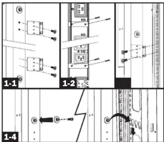
Mounting the PDU
Note: The illustrations may differ somewhat from your PDU model. Regardless of configuration, the user must determine the fitness of hardware and procedures before mounting. The PDU and included hardware are designed for common rack and rack enclosure types and may not be appropriate for all applications. Exact mounting configurations may vary. Screws for attaching the mounting brackets and cord retention shelf to the PDU are included. Use only the screws supplied by the manufacturer, or their exact equivalent (#6-32, 14 flat head).
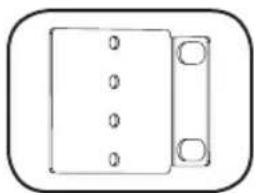
1-1 Attach the mounting brackets to the PDU.
1-2 (Optional) Attach the cord retention bracket(s) to the PDU.
1-3 Attach the PDU to a vertical rail in your rack or rack enclosure. (Use the mounting hardware that came with your rack or rack enclosure to attach the mounting brackets to the rail.)
1-4 For toolless mounting, attach the included mounting buttons to the PDU. Position the PDU as desired in the rack enclosure, align the buttons with the rack mounting slots, and slide the PDU into position.
Installation
Connecting the PDU

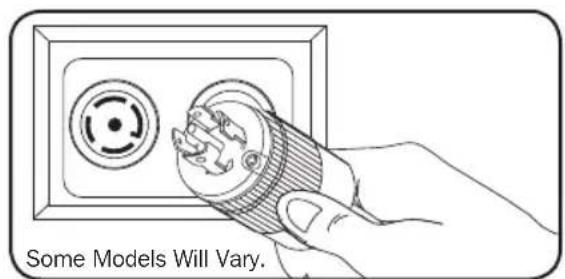
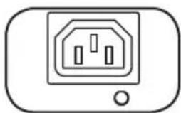
Each model is equipped with 1 of 8 different input plugs.

16A Red IEC 3093P+N+E

30A Blue IEC 3093P+E

60A Blue IEC 3093P+E

Hubbell CS8365C

L15-30P L21-30P L21-20P L15-20P


PDU3VSR-Switched, Metered and Networked—0U, Vertical Strip Cabinet Style
| Model # Input Plug | Max Amps (Limited by input plug) | Input Voltage | Output Voltage | Balanced Output Current per Phase | Cord Length | Outlets | Outlet Control | |
| PDU3VSR3G30 PDU3VSR10G30 | 30A Blue IEC 309 3P+E | 24 | 208 208 | 13.9 A | 10 ft. or 3 ft. | 3 Banks of (7) C13s and (1) C19 | Yes | |
| PDU3VSR3G60 PDU3VSR10G60 | 60A Blue IEC 309 3P+E | 35 | 208 208 | 20.0 A | ||||
| PDU3VSR3H50 PDU3VSR10H50 | Hubbell CS8365C | 35 | 208 208 | 20.0 A | ||||
| PDU3VSR3L1530 PDU3VSR10L1530 | L15-30P | 24 | 208 208 | 13.9 A | ||||
| PDU3VSR3L2130 PDU3VSR10L2130 | L21-30P | 24 | ||||||
| PDU3VSR3L2120 PDU3VSR10L2120 | L21-20P | 16 | 208 208 | 9.2 A | ||||
| PDU3VSR3L1520 PDU3VSR10L1520 | L15-20P | 16 | ||||||
| PDU3XVSR3G16 PDU3XVSR10G16 | 16A Red IEC 309 3P+N+E | 16 | 230/400 | 230 16.0 A |
PDU3VN-Metered and Networked—0U, Vertical Strip Cabinet Style
| Model # Input Plug | Max Amps (Limited by input plug) | Input Voltage | Output Voltage | Balanced Output Current per Phase | Cord Length | Outlets | Outlet Control | |
| PDU3VN3G30 PDU3VN10G30 | 30A Blue IEC 309 3P+E | 24 | 208 208 | 13.9 A | 10 ft. or 3 ft. | 3 Banks of (10) C13s and (2) C19 | No | |
| PDU3VN3G60 PDU3VN10G60 | 60A Blue IEC 309 3P+E | 35 | 208 208 | 20.0 A | ||||
| PDU3VN3H50 PDU3VN10H50 | Hubbell CS8365C | 35 | 208 208 | 20.0 A | ||||
| PDU3VN3L1530 PDU3VN10L1530 | L15-30P | 24 | 208 208 | 13.9 A | ||||
| PDU3VN3L2130 PDU3VN10L2130 | L21-30P | 24 | ||||||
| PDU3VN3L2120 PDU3VN10L2120 | L21-20P | 16 | 208 208 | 9.2 A | ||||
| PDU3VN3L1520 PDU3VN10L1520 | L15-20P | 16 | ||||||
| PDU3XVN3G16 PDU3XVN10G16 | 16A Red IEC 309 3P+N+E | 16 | 230/400 | 230 16 | 6.0 A |
Installation
Connecting the PDU
2-2 Connect the input plug to your facility's compatible AC power source.
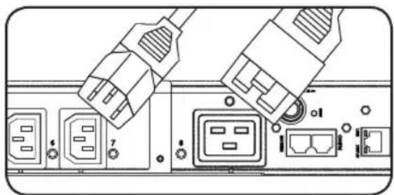
2-3 Both models contain 3 banks of output receptacles. PDU3VSR (3 banks of 7 C13s and 1 C19). PDU3VN (3 banks of 10 C13s and 2 C19s). Connect your equipment's input plugs to the appropriate outlets on the PDU. On the Switched models, the LED near each outlet illuminates when the outlet is ready to distribute live AC power.
Note: It is recommended that you do not connect a live load to the PDU. If the load you intend to connect has an ON/OFF switch, please turn the switch to OFF prior to connection.
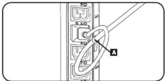
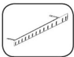
2-4 (Optional) If you attached the cord retention bracket(s), tie each equipment power cord to the retention bracket. Attach each cord to the retention shelf by looping the cord and securing it with one of the included cable ties A. Make sure each cord can be unplugged from the PDU without removing the cable tie.
Networking the PDU
Note: The MAC address of the PDU (a 12-digit string in this format: 000667xxxxx) is printed on a label attached to the PDU enclosure.
If your network's DHCP server will assign a dynamic IP address to the PDU automatically, go to Step 3-1. If you will assign a static IP address to the PDU manually, go to Step 4-1. If you are uncertain which method to use, contact your network administrator for assistance before continuing the installation process.
Dynamic IP Address Assignment
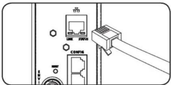
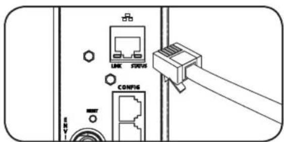
3-1 Connect PDU to Network: While the PDU is powered, connect a standard Ethernet patch cable to the RJ-45 Ethernet port on the PDU.
Note: This port is not compatible with PoE (Power over Ethernet) applications. The PDU will attempt to obtain an IP address via DHCP. This may take as long as several minutes, depending on your network environment.
Installation
Dynamic IP Address Assignment

Discover IP Address: Contact your network administrator to determine which dynamic IP address has been assigned to the PDU by the DHCP server. The PDU can be identified on the DHCP server by referring to its MAC address. (The MAC address is a 12-digit string in this format: 000667xxxxxx. Refer to the MAC address label attached to the PDU.) You may wish to request a long-term lease period for the IP address, depending on your application. After you have discovered the IP address, skip Steps 4-1 through 4-6 and proceed directly to Step 5-1.

Alternate Method: Press and hold Button B on the Digital Load Meter (see page 8) for 4 seconds to display the IP Address. The default is no address assigned. If this is the case, "no address" will display one letter at a time. If there is an IP Address programmed, the address will display 1 digit at a time with dashes (-) representing dots or periods (.).
Static IP Address Assignment

Determine IP Information: Before assigning a static IP address, you'll need to know the IP address, gateway address and subnet mask. If you do not have this information, contact your network administrator for assistance.

Configure Terminal Emulation Program: Open a VT100-compatible terminal emulation program (such as the HyperTerminal program bundled with Microsoft Windows) on a computer with an available DB9 serial port. (A notebook computer may be the most convenient choice.) Set the terminal emulation program to use the COM port that corresponds to the computer's DB9 serial port. Specify the parameters required to communicate with the PDU terminal interface:
Bits per second: 9600 Stop bits: 1 Data bits: 8 Flow Control: None Parity: None
If the terminal emulation program supports multiple emulation modes, you may also need to specify VT100 emulation.

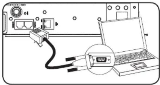
Connect PDU to Computer: Use the RJ-45 to DB9 configuration cable (part number 73-1243) included with the PDU to connect the PDU to the computer. The connector at one end of the cable attaches to the CONFIG RJ-45 port on the PDU. The DB9 connector at the other end of the cable connects to the computer's serial port.

Press SNMP Reset Button: Press the reset button for 3 seconds to reboot the PDU's network card. Rebooting the network card will not erase network settings or interrupt AC power.
Installation
Static IP Address Assignment
4-5
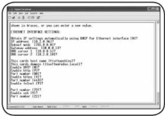
Configure PDU in Terminal Mode: After a brief pause, an initialization page should appear in the terminal emulation program. Press any key on the keyboard within 10 seconds to change the PDU settings. (If the 10-second period has elapsed, you can reboot the PDU by powering down completely and then restoring power.)
Follow the sequence of responses below in order to assign an IP address to the PDU. The default terminal mode root password is TrippLite. Sample IP settings are shown - supply your own IP information when you configure your PDU.
Press A to Accept the settings, or M to Modify? M
Enter the root password: *******
Reset configuration to default values (Y/N)? N
For each of the following questions, you can press
NETWORK INTERFACE PARAMETERS:
Should this target obtain IP settings from the network?[N] N
Static IP address [192.168.1.19]? 192.168.0.123
Static IP address is 192.168.0.123
Subnet Mask IP address [255.255.0.0]? 255.255.255.0
Subnet Mask IP address is 255.255.255.0
Gateway address IP address [192.168.1.1]? 192.168.0.1
Gateway address IP address is 192.168.0.1
You can also change the root password, real-time clock and other settings. (Tripp Lite recommends against changing the default settings unless you are an advanced user with a specific purpose.) After you have finished entering settings, the PDU will save changes to memory and reboot (this may take several minutes). After the PDU reboots, the initialization page should display the new static IP settings.
4-6
Remove Serial Cable: Remove the serial cable from the PDU and proceed to Step 5.
Network Connection
5-1
Connect PDU to Network: While the PDU is powered, connect a standard Ethernet patch cable to the RJ-45 Ethernet port on the PDU.
Note: This port is not compatible with PoE (Power over Ethernet) applications.
Installation
Network Connection

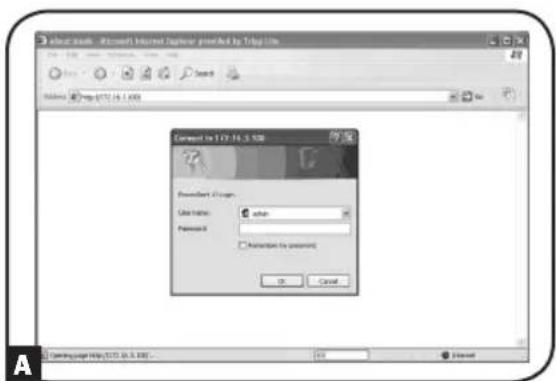
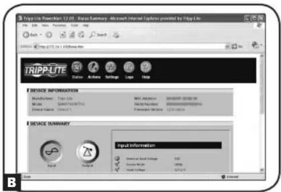
Access PDU with Web Browser: After an IP address has been assigned to the PDU, attempt to access it with a Web browser that supports frames, forms and Java. Open a Web browser on a computer connected to the LAN and enter the IP address assigned to the PDU. You should be prompted for a password. The user name is admin and the default password is admin. After you enter the user name and password, the PowerAlert status page will appear in the browser window. For more information about configuration and operation of the PDU via the PowerAlert interface, refer to the SNMPWEBCARD User's Guide, included on the CD-ROM bundled with the PDU.
Note for Network Management System Users Only: Two MIB files - Tripplite.mib and RFC1628.mib - must be loaded on each Network Management Station that will monitor the PDU via SNMP. The files are provided on the CD-ROM included in the product package.
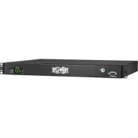
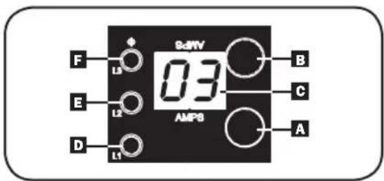
Digital Load Meter

Phase Current/Flip Display Button:
This button A can be pressed to show total current for each of the three outlet groups or Phases. Pressing this button once will display the total current for all of the outlets on Phase Bank 1, located nearest to the input cord. The LED for Phase 1 D will illuminate and the total current for Phase 1 outlets will display in amps in the LED Amps display C. Pressing this button A a second time will produce the same results for Phase Bank 2 and a third time for Phase Bank 3. The appropriate LEDs E or F will also illuminate and amps will appear in the display C. Pressing the button additional times will repeat the cycle.
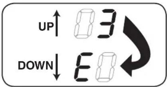
If you press and hold this button for 4 seconds, the numbers in the LED Amps display will flip for mounting versatility. The unit can be mounted with the power cord facing the top or bottom while still being able to read the display.
Digital Load Meter
2 Receptacle Current/IP Show Button (Model PDU3VSR & PDU3XVSR Only):
This button can be pressed to show the current for each individual outlet. Pressing this button once will display the current for the first individual outlet, located nearest the input cord. The LED for Phase 1 will flash (because this outlet is included in the Phase 1 outlets) as will the LED located next to the outlet itself and the total current for that outlet will display in amps in the LED Amps display. Pressing this button a second time will produce the same results for outlet 2, pressing a third time for outlet 3 and so on through all the outlets.
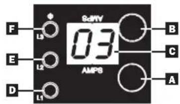
Note: The LED for Phases 1, 2 and 3
D, E and F will all flash accordingly as you move between
outlets and their respective Phases. Outlets 1-8 will flash Phase 1 LED D, outlets 9-16 will flash
Phase 2 LED and outlets 17-24 will flash Phase 3 LED
(For All Models): If you press and hold this button
B for 4 seconds you can display the
IP Address assigned to the unit in the LED Amps display c. The default is no address
assigned. If this is the case, "no address" will display, one letter at a time. If there is an IP Address programmed, the address will display 1 digit at a time with dashes (-) representing dots or periods (.).

Features
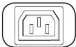
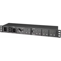
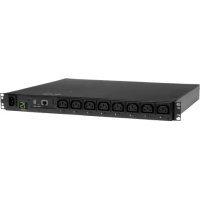
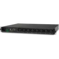
IEC-60320-C13
Outlets: During normal operation, the outlets distribute AC power to connected equipment.
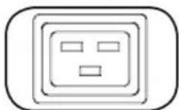
IEC-60320-C19

Outlet LED: Once the unit is powered-on, each outlet individually ramps up and each outlet LED will illuminate when the associated outlet is ready to distribute live AC power (PDU3VSR & PDU3XVSR models only).
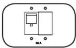
Circuit Breaker: Each phase has its own breaker labeled L1 (Phase 1), L2 (Phase 2) and L3 (Phase 3). If the connected equipment load exceeds the Maximum Load Rating for that phase of the PDU, the circuit breaker will trip. Disconnect excess equipment and allow the breaker to cool before resetting the breaker (models rated at 24A or greater input current only).
Cord Retention Bracket: Provides secure attachment points for connected equipment cords.
Mounting Brackets: Use these brackets to mount the PDU.
SNMP Reset Button: Press the reset button for 3 seconds to reboot the PDU's network card. Rebooting the network card will not erase network settings or interrupt AC power.
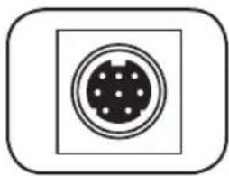
PS/2 Port: Use this port to connect a Tripp Lite ENVIROSENSE environmental sensor to provide remote temperature/humidity monitoring and a dry contact interface to control and monitor alarm, security and telecom devices. Visit www.triplite.com for ordering information. Note: Do not connect a keyboard or mouse to this port.
Features
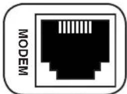
RJ-45 Modem Port: Reserved for future use.
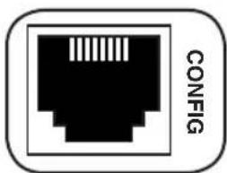
RJ-45 CONFIG Port: The port is reserved for configuration by factory authorized personnel only. Do not connect anything to this port.
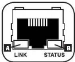
Ethernet Port: Use this RJ-45 jack to connect the PDU to the network with a standard Ethernet patch cable. The Link LED A and Status LED B indicate several operating conditions, as shown in the table below. This port is not compatible with PoE (Power Over Ethernet) applications.
| Network Operating Conditions | |
| A Link LED Color | |
| Off No Network Connection | |
| Flashing Amber 100 Mbps Network Connection | |
| Flashing Green 10 Mbps Network Connection | |
| B Status LED Color | |
| Off Card Not Initialized | |
| Steady or Flashing Green Card Initialized and Operational | |
| Steady Amber Error - Card Not Initialized | |
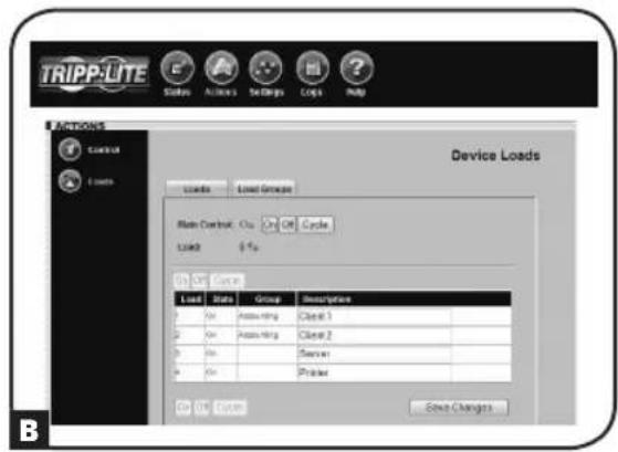
Configuration and Operation
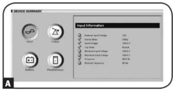
Remote Monitoring and Control
The PDU provides remote monitoring A, outlet control B and more via Web browser, telnet and SNMP-based Network Management Systems. For more information about configuration and operation of the PDU via thePowerAlert Web browser interface, refer to the SNMPWEBCARD User's Guide, included on the CD-ROM bundled with the PDU.
Service
Your Tripp Lite product is covered by the warranty described in this manual. A variety of Extended Warranty and On-Site Service Programs are also available from Tripp Lite. For more information on service, visit www.triplite.com/support. Before returning your product for service, follow these steps:
- Review the installation and operation procedures in this manual to insure that the service problem does not originate from a misreading of the instructions.
- If the problem continues, do not contact or return the product to the dealer. Instead, visit www.triplite.com/support.
- If the problem requires service, visit www.triplite.com/support and click the Product Returns link. From here you can request a Returned Material Authorization (RMA) number, which is required for service. This simple on-line form will ask for your unit's model and serial numbers, along with other general purchaser information. The RMA number, along with shipping instructions will be emailed to you. Any damages (direct, indirect, special or consequential) to the product incurred during shipment to Tripp Lite or an authorized Tripp Lite service center is not covered under warranty. Products shipped to Tripp Lite or an authorized Tripp Lite service center must have transportation charges prepaid. Mark the RMA number on the outside of the package. If the product is within its warranty period, enclose a copy of your sales receipt. Return the product for service using an insured carrier to the address given to you when you request the RMA.
Warranty and Warranty Registration
2- YEAR LIMITED WARRANTY
Seller warrants this product, if used in accordance with all applicable instructions, to be free from original defects in material and workmanship for a period of 2 years from the date of initial purchase. If the product should prove defective in material or workmanship within that period, Seller will repair or replace the product, in its sole discretion. Service under this Warranty can only be obtained by your delivering or shipping the product (with all shipping or delivery charges prepaid) to: Tripp Lite, 1111 W. 35th Street, Chicago, IL 60609 USA. Seller will pay return shipping charges. Visit www.triplite.com/support before sending any equipment back for repair.
THIS WARRANTY DOES NOT APPLY TO NORMAL WEAR OR TO DAMAGE RESULTING FROM ACCIDENT, MISUSE, ABUSE OR NEGLECT. SELLER MAKES NO EXPRESS WARRANTY OTHER THAN THE WARRANTY EXPRESSLY SET FORTH HEREIN. EXCEPT TO THE EXTENT PROHIBITED BY APPLICABLE LAW, ALL IMPLIED WARRANTYES, INCLUDING ALL WARRANTYES OF MERCHANTABILITY OR FITNESS, ARE LIMITED IN DURATION TO THE WARRANTY PERIOD SET FORTH ABOVE; AND THIS WARRANTY EXPRESSLY EXCUSES ALL INCIDENTAL AND CONSEQUENTIAL DAMAGES. (Some states do not allow limitations on how long an implied warranty lasts, and some states do not allow the exclusion or limitation of incidental or consequential damages, so the above limitations or exclusions may not apply to you. This Warranty gives you specific legal rights, and you may have other rights which vary from jurisdiction to jurisdiction).
WARNING: The individual user should take care to determine prior to use whether this device is suitable, adequate or safe for the use intended. Since individual applications are subject to great variation, the manufacturer makes no representation or warranty as to the suitability or fitness of these devices for any specific application.
WARRANTY REGISTRATION
Visit www.triplite.com/warranty today to register the warranty for your new Tripp Lite product. You'll be automatically entered into a drawing for a chance to win a FREE Tripp Lite product!*
- No purchase necessary. Void where prohibited. Some restrictions apply. See website for details.
FCC Notice, Class A
This device complies with part 15 of the FCC Rules. Operation is subject to the following two conditions: (1) This device may not cause harmful interference, and (2) this device must accept any interference received, including interference that may cause undesired operation.
Note: This equipment has been tested and found to comply with the limits for a Class A digital device, pursuant to part 15 of the FCC Rules. These limits are designed to provide reasonable protection against harmful interference when the equipment is operated in a commercial environment. This equipment generates, uses, and can radiate radio frequency energy and, if not installed and used in accordance with the instruction manual, may cause harmful interference to radio communications. Operation of this equipment in a residential area is likely to cause harmful interference in which case the user will be required to correct the interference at his own expense. The user must use shielded cables and connectors with this equipment. Any changes or modifications to this equipment not expressly approved by
Tripp Lite could void the user's authority to operate this equipment.
Regulatory Compliance Identification Numbers
For the purpose of regulatory compliance certifications and identification, your Tripp Lite product has been assigned a unique series number. The series number can be found on the product nameplate label, along with all required approval markings and information. When requesting compliance information for this product, always refer to the series number. The series number should not be confused with the marking name or model number of the product.
WEEE Compliance Information for Tripp Lite Customers and Recyclers (European Union)
Under the Waste Electrical and Electronic Equipment (WEEE) Directive and implementing regulations, when customers buy new electrical and electronic equipment from Tripp Lite they are entitled to:
- Send old equipment for recycling on a one-for-one, like-for-like basis (this varies depending on the country)
- Send the new equipment back for recycling when this ultimately becomes waste
The policy of Tripp Lite is one of continuous improvement. Specifications are subject to change without notice.

1111 W. 35th Street, Chicago, IL 60609 USA www.triplite.com/support
1111 W. 35th Street, Chicago, IL 60609 USA
www.triplite.com/support
PDU3VN-Metered and Networked—0U, Vertical Strip Cabinet Style
| Modelo Nro. Enchufe de | entrada | Máx. Amp. (Limitado por el enchufe de entrada) | Tensión de entrada | Tensión de salida | Corriente de salle balanceada por fase | Longitud del cable | Toma- corrientes | Control del tomaco- rriente |
| PDU3VN3G30 PDU3VN10G30 | 30A Blue IEC 309 3P+E | 24 | 208 208 | 13.9 A | 10 pies o 3 pies | 3 Bancos de(10) C13s y (2) C19 | No | |
| PDU3VN3G60 PDU3VN10G60 | 60A Blue IEC 309 3P+E | 35 | 208 208 | 20.0 A | ||||
| PDU3VN3H50 PDU3VN10H50 | Hubbell CS8365C | 35 | 208 208 | 20.0 A | ||||
| PDU3VN3L1530 PDU3VN10L1530 | L15-30P | 24 | 208 208 | 13.9 A | ||||
| PDU3VN3L2130 PDU3VN10L2130 | L21-30P | 24 | ||||||
| PDU3VN3L2120 PDU3VN10L2120 | L21-20P | 16 | 208 208 | 9.2 A | ||||
| PDU3VN3L1520 PDU3VN10L1520 | L15-20P | 16 | ||||||
| PDU3XVN3G16 PDU3XVN10G16 | 16A Red IEC 309 3P+N+E | 16 | 230/400 | 230 16 | 6.0 A A |
Instalación
Conexión de la PDU

1111 W. 35th Street, Chicago, IL 60609 USA www.triplite.com/support
1111 W. 35th Street, Chicago, IL 60609 USA www.triplite.com/support
1111 W. 35th Street, Chicago, IL 60609 USA
www.triplite.com/support