
APSX3024SW - Inverter Tripp Lite - Free user manual and instructions
Find the device manual for free APSX3024SW Tripp Lite in PDF.

| Device Type | Inverter/Charger |
| Brand | Tripp Lite |
| Model | APSX3024SW |
| DC Input Voltage | 24 V DC |
| AC Output Voltage | 230 V AC (DIP switch selectable) |
| Continuous Output Power | 3000 W |
| Waveform | Pure Sine Wave |
| Output Frequency | 50/60 Hz selectable |
| Transfer Time | 1/2 cycle or 1 cycle adjustable |
| Battery Charge Current | 23 A (low) or 90 A (high) selectable |
| Compatible Battery Types | Gel/AGM (sealed) or wet cell (vented) |
| OverPower Feature | Up to 150% of rated power for 1 to 60 minutes |
| DoubleBoost Feature | Up to 200% for 10 seconds |
| Protections | Overload, overheat, over-discharge, battery overvoltage |
| Connectivity | DC terminals, AC terminal block, remote control connector, battery temperature sensor, generator starter |
| Warranty | 2-year limited |
Frequently Asked Questions - APSX3024SW Tripp Lite
User questions about APSX3024SW Tripp Lite
0 question about this device. Answer the ones you know or ask your own.
Ask a new question about this device
Download the instructions for your Inverter in PDF format for free! Find your manual APSX3024SW - Tripp Lite and take your electronic device back in hand. On this page are published all the documents necessary for the use of your device. APSX3024SW by Tripp Lite.
USER MANUAL APSX3024SW Tripp Lite
APSX Pure Sine Wave DC-to-AC Inverter/Chargers
Models: APSX3024SW, APSX6048VRNET
Introduction 2
Important Safety Instructions 2
Feature Identification 3
Operation 4
Configuration 5
Battery Selection 8
Battery Connection 9
AC Input/Output Connection 10
AC Generator Input 10
Service/Maintenance 11
Troubleshooting 11
Warranty 12
Español 13
Français 25
Русский 37

text_image
TRIPP·LITE
Introduction
Congratulations! You've purchased the most advanced, feature-rich Inverter/Charger designed as an alternative energy source during utility power failures. Tripp Lite APS Inverter/Chargers keep your equipment constantly up and productive through all utility power problems (blackouts, brownouts and high voltages) by automatically inverting DC power from user-supplied batteries into AC power. Built-in Isobar® surge suppression provides an additional level of equipment protection. When utility power is present, APS Inverter/Chargers automatically pass through power to your equipment while simultaneously recharging your connected battery bank. APS Inverter/Chargers are the quiet alternative to gas generators during emergency backup applications—with no fumes, fuel or noise to deal with! You get AC electricity anywhere and anytime you need it.
Important Safety Instructions

SAVE THESE INSTRUCTIONS!
This manual contains important instructions and warnings that should be followed during the installation, operation and storage of all Tripp Lite Inverter/Chargers.
Location Warnings
• Install your Inverter/Charger in a location or compartment that minimizes exposure to heat, dust, direct sunlight and moisture.
- Although your Inverter/Charger is moisture resistant, it is NOT waterproof. Flooding the unit with water will cause it to short circuit and could cause personal injury due to electric shock. Never immerse the unit, and avoid any area where standing water might accumulate. Mounting should be in the driest location available.
- Leave a minimum of 50 mm clearance at front and back of the Inverter/Charger for proper ventilation. The heavier the load of connected equipment, the more heat will be generated by the unit.
- Do not install the Inverter/Charger directly near magnetic storage media, as this may result in data corruption.
- Do not install near flammable materials, fuel or chemicals.
- Do not mount unit with its front or rear panel facing down (at any angle). Mounting in this manner will seriously inhibit the unit's internal cooling, eventually causing product damage not covered under warranty.
- Mount your Inverter/Charger BEFORE DC battery and AC power connection. Failure to follow these instructions may lead to personal injury and/or damage to the Inverter/Charger and connected systems.
Battery Connection Warnings
- The battery should be connected before operating the Inverter/Charger.
- Multiple battery systems must be comprised of batteries of identical voltage, age, amp-hour capacity and type.
- Because explosive hydrogen gas can accumulate near batteries if they are not kept well ventilated, your batteries should not be installed in a “dead air” compartment. Ideally, any compartment would have some ventilation to outside air.
- Sparks may result during final battery connection. Always observe proper polarity as batteries are connected.
- Do not allow objects to contact the two DC input terminals. Do not short or bridge these terminals together. Serious personal injury or property damage could result.
Equipment Connection Warnings
- Use of this equipment in life support applications where failure of this equipment can reasonably be expected to cause the failure of the life support equipment or to significantly affect its safety or effectiveness is not recommended. Do not use this equipment in the presence of a flammable anesthetic mixture with air, oxygen or nitrous oxide.
- Connect your Inverter/Charger only to a properly grounded AC power source. Do not connect the unit to itself; this will damage the device and void your warranty.
- The main grounding lug should be connected to earth ground with a minimum 3.15 mm diameter 8 AWG wire.
Operation Warnings
- Your Inverter/Charger does not require routine maintenance. Do not open the device for any reason. There are no user serviceable parts inside.
- Potentially lethal voltages exist within the Inverter/Charger as long as the battery supply and/or AC input are connected. During any service work, the battery supply and AC input connection should therefore be disconnected.
- Do not connect or disconnect batteries while the Inverter/Charger is operating in either inverting or charging mode. Operating Mode Switch should be in the OFF position. Dangerous arcing may result.
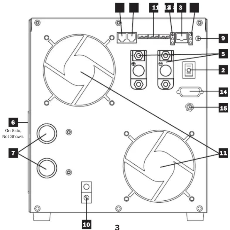
Feature Identification
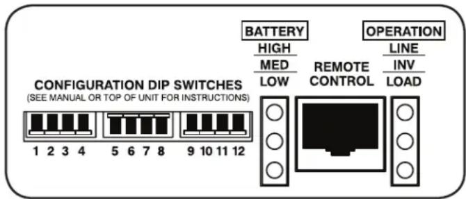
1 Configuration DIP Switches: Optimize Inverter/Charger operation depending on your application. See Configuration section for setting instructions.
2 Operating Mode Rocker Switch: Controls Inverter/Charger operation. The "AUTO/REMOTE" setting ensures your equipment receives constant, uninterrupted AC power. It also enables the Inverter/Charger to be remotely monitored and controlled with an optional remote module (Tripp Lite model APSRM4, sold separately). The "CHARGE ONLY" setting allows your batteries to return to full charge faster by turning the inverter off, which halts battery discharging. The "OFF" position de-energizes the unit (including its AC output). See Operation section for setting instructions.
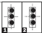
3 Operation Indicator Lights: Intuitive "traffic light" signals show whether the Inverter/Charger is operating from AC line power or DC battery power. It also warns you if the connected equipment load is too high. See Operation section for instructions on reading indicator lights.
4 Battery Indicator Lights: Intuitive "traffic light" signals show approximate charge level of your battery. See Operation section for instructions on reading indicator lights.
5 DC Power Terminals: Connect to your battery terminals. See Battery Connection section for connection instructions.
6 Hardwire AC Input/Output Terminal Strip (Access Panel): Securely connects the Inverter/Charger to facility electrical system. See Input/Output Connection section for connection instructions.
7 Knockouts for AC Input/Output Conduits
8 Remote Control Module Connector: Allows remote monitoring and control with an optional module (Tripp Lite model APSRM4, sold separately). See remote module owner's manual for connection instructions.
9 Battery Charge Conserver (Load Sense) Control: Conserves battery power by setting the low-load level at which the Inverter/Charger's inverter automatically shuts off. See Configuration section for setting instructions.
10 Main Ground Lug: Properly grounds the Inverter/Charger to earth ground. See Battery Connection section for connection instructions.
1.1 Thermostatically Controlled Cooling Fans: Quiet, efficient fans regulate internal temperature and prolong equipment service life. Fans run at variable speed, depending on temperature and load.
12 Remote Generator Start Connector: Automatically cycles generator based on battery voltage. Use with user-supplied cable. See Configuration section for more information.
13 Remote Battery Temperature Sensing Connector: Prolongs battery life by adjusting charge based on battery temperature. Contact Tripp Lite for optional temperature sensing cable accessory. See Configuration section for more information.
14 RS-232 Serial Communication Connector (APSX6048VRNET only): Can be used to attach an external SNMP/Web management module (Tripp Lite model SNMPWEBSOLOHV) to remotely monitor your inverter/charger.
15 12V DC Power Connector (APSX6048VRNET only): Independently powers SNMP/Web management module (Tripp Lite model SNMPWEBSOLOHV) without the use of an AC outlet.
text_image
6 On Side, Not Shown. 7 10 3 11 12 13 14 15 9 5 2 14 11Operation
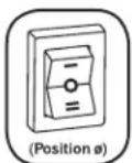
Switch Modes
After configuring, mounting and connecting your Inverter/Charger, you are able to operate it by switching between the following operating modes as appropriate to your situation:
AUTO/REMOTE: Switch to this mode when you need constant, uninterrupted AC power for connected appliances and equipment. The Inverter/Charger will continue to supply AC power to connected equipment and to charge your connected batteries while utility- or generator-supplied AC power is present. Since the inverter is ON (but in Standby) in this mode, it will automatically switch to your battery system to supply AC power to connected equipment in the absence of a utility/generator source or in over/under voltage situations. "AUTO/REMOTE" also enables an optional remote control module (Tripp Lite model APSRM4, sold separately) to function when connected to the unit.
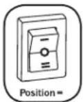
CHARGE ONLY: Switch to this mode when you are not using connected appliances and equipment in order to conserve battery power by disabling the inverter. The Inverter/Charger will continue to pass through AC power to connected equipment and charge connected batteries while utility- or generator-supplied AC power is present. However, since the inverter is OFF in this mode, NOT supply AC power to connected equipment in the a utility/generator source or in over/under voltage situation
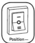
OFF: Switch to this mode to shut down the Inverter/Charger completely, preventing the inverter from drawing power from the batteries, and preventing utility AC from passing through to connected equipment or charging the batteries. Use this switch to automatically reset the unit if it shuts down due to overload or overheating. First remove the excessive load or allow the unit to sufficiently cool (applicable to your situation). Switch to "OFF", then back to "AUTO/REMOTE" or "CHARGE ONLY" as desired. If unit fails to reset, remove more load or allow unit to cool further and retry.
Note: The optional remote control module (APSRM4) will only reset overloads.
Indicator Lights
Your Inverter/Charger (as well as an optional Tripp Lite Remote Control Module, sold separately) is equipped with a simple, intuitive, user-friendly set of indicator lights. These easily remembered “traffic light” signals will allow you, shortly after first use, to tell at a glance the charge condition of your batteries, as well as ascertain operating details and fault conditions.
LINE Green Indicator: If the operating mode switch is set to "AUTO/REMOTE," this light will ILLUMINATE CONTINUOUSLY when your connected equipment is receiving continuous AC power supplied from a utility/generator source.
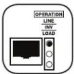
If the operating mode switch is set to "CHARGE ONLY," this light will FLASH to alert you that the unit's inverter is OFF and will NOT supply AC power in the absence of a utility/generator source or in over/under voltage situations.
INV (Inverting) Yellow Indicator: This light will ILLUMINATE CONTINUOUSLY whenever connected equipment is receiving battery-supplied, inverted AC power (in the absence of a utility/generator source or in over/under voltage situations). This light will be off when AC power is supplying the load. This light will FLASH to alert you if the load is less than the Battery Charge Conserver (Load Sense) setting.
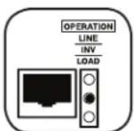
LOAD Red Indicator: This red light will ILLUMINATE CONTINUOUSLY whenever the inverter is functioning and the power demanded by connected appliances and equipment exceeds 100% of load capacity. The light will FLASH to alert you when the inverter shuts down due to a severe overload or overheating. If this happens, turn the operating mode switch "OFF"; remove the overload and let the unit cool. You may then turn the operating mode switch to either "AUTO/REMOTE" or "CHARGE ONLY" after it has adequately cooled. This light will be off when AC power is supplying the load.
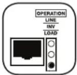
BATTERY Indicator Lights: These three lights will illuminate in several sequences to show the approximate charge level of your connected battery bank and alert you to two fault conditions:
Approximate Battery Charge Level\*
Indicator Illuminated Battery Capacity (Charging/Discharging)
1 Green 91%–Full
2 Green & Yellow 81%–90%
3 Yellow 61%-80%
4 Yellow & Red 41%–60%
5 Red 21%-40%
6 All three lights off 1%–20%
7 Flashing red 0% (Inverter shutdown)
* Charge levels listed are approximate. Actual conditions vary depending on battery condition and load.
text_image
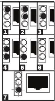
1 2 3 4 5 6 7Fault Condition
Indicator Illuminated Fault Condition
1 All three lights Excessive discharge flash slowly* (Inverter shutdown)
2 All three lights Overcharge (Charger flash quickly** shutdown)
*Approximately 12 second on, 12 second off. See Troubleshooting section. ** Approximately 14 second on, 14 second off. May also indicate a battery charger fault exists. See Troubleshooting section.
Resetting Your Inverter/Charger to Restore AC Power
Your Inverter/Charger may cease supplying AC power or DC charging power in order to protect itself from overload or to protect your electrical system. To restore normal functioning:
Overload Reset: Switch operating mode switch to "OFF" and remove some of the connected electrical load (ie: turn off some of the AC devices drawing power which may have caused the overload of the unit). Wait one minute, then switch operating mode switch back to either "AUTO/REMOTE" or "CHARGE ONLY."
Configuration
Set Configuration DIP Switches
Using a small tool, set the Configuration DIP Switches (located on the front panel of your unit, see diagram) to optimize Inverter/Charger operation depending on your application. Warning: Make sure the unit is turned OFF before changing DIP Switch settings.
text_image
BATTERY HIGH MED LOW REMOTE CONTROL LINE INV LOAD OPERATION CONFIGURATION DIP SWITCHES (SEE MANUAL OR TOP OF UNIT FOR INSTRUCTIONS) 1 2 3 4 5 6 7 8 9 10 11 121 Not Used
2 Select Line Connect Relay Transfer Time - OPTIONAL Transfer Time Switch Position
1/2 Cycle Transfer Time Up
1 Cycle Transfer Time Down (factory setting)
Note: The Inverter/Charger's default transfer time setting is 1 cycle, which provides optimal protection for standard loads in areas with frequent outages. If you will use the Inverter/Charger to support computers or other sensitive electronic equipment loads, set the transfer time to 12 cycle (switch #2 UP) to ensure uninterrupted operation when the Inverter/Charger transfers to battery power.
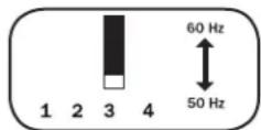
3 Select Frequency - REQUIRED Frequency Switch Position
60 Hz Up
50 Hz Down (factory setting)
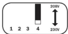
4 Select Line Voltage - REQUIRED (APSX6048VRNET model only) Voltage Switch Position
208 VAC Up
230 VAC Down (factory setting)
5 Select Battery Charger Amp Setting
CAUTION: When switching to the High Charge Amp setting, the user must ensure that the amp-hour capacity of their battery system exceeds the amperage of the High Charge Amp setting or the batteries may be damaged or degraded.
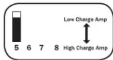
Battery Charger Switch Position
Low Charge Amps (23A) Up (factory setting)
High Charge Amps (90A) Down
6 Select Equalize Battery Charge - OPTIONAL
Switch this DIP switch to the down position for 3 seconds to begin the process of equalizing the charge state of your battery's cells by time-limited overcharge of all cells. This can extend the useful life of certain types of batteries; consult with your battery's manufacturer to determine if your batteries could benefit from this process. The charge equalization process is automatic; once started, it can only be stopped by removing the input power.
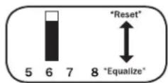
Setting Procedure
- Move to "Equalize" (DOWN) position for 3 seconds.
- Move to "Reset" (UP) position and leave it there. This is the factory default setting. CAUTION: Do not leave DIP switch #6 in the down position after beginning process. Battery charge equalization should only be performed in strict accordance with the battery manufacturer's instructions and specifications.
Battery Charge Switch Position
Reset Up (factory setting)
Equalize Down (3 seconds)
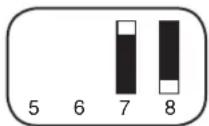
7 8 Select AC Input Current Sharing—OPTIONAL
(APSX3024SW model only; APSX6048VRNET model operates in "Most Limiting" mode only)
Your Inverter/Charger features a high-output battery charger that can draw a significant amount of AC power from your utility source or generator when charging at its maximum rate. If your unit is supplying its full AC power rating to its connected heavy electrical loads at the same time as this high charging occurs, the AC input circuit breaker could trip, resulting in the complete shut off of pass-through utility power.
Configuration
To reduce the chance of tripping this breaker, all Inverter/Chargers are pre-set to automatically limit the input current as described in "Most Limiting" below. If your unit is equipped with DIP switches 7 and 8, they may be used to select other AC input current sharing settings. Verify that AC input wiring is rated for the higher current that results when using the other settings.
Select Battery Charger-Limiting Points
"Most Limiting" (#7 & #8 Up): Charger-limiting takes effect the moment any AC load is applied; charger output falls gradually from full output at no AC load passing through to no output at full load (factory setting).
"Less Limiting" (#7 Up & #8 Down):
Charger-limiting begins when the Inverter/Charger's load reaches 33% of the Inverter/Charger's load rating. Charger output falls gradually from full output at 33% of the
Inverter/Charger's load rating to about 33% of full output at full load.
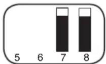
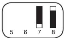
"Least Limiting" (#7 Down & #8 Up):
Charger-limiting begins when the Inverter/Charger's load reaches 66% of the Inverter/Charger's load rating. Charger output falls gradually from full output at 66% of the
Inverter/Charger's load rating to about 66% of full output at full load.
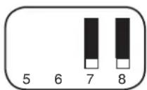
"No Limiting" (#7 & #8 Down): No charger-limiting occurs at any load size.
230V Operation (APSX3024SW)
9 10 Select Low VAC Input Voltage Point for Switching to Battery - OPTIONAL\*
Voltage 9, 10 Switch Position
| 180 VAC | Up, Up | 9 | 10 | 11 | 12 |
| 170 VAC | Up, Down | 9 | 10 | 11 | 12 |
| 160 VAC | Down, Up | 9 | 10 | 11 | 12 |
| 150 VAC | Down, Down (factory setting) | 9 | 10 | 11 | 12 |
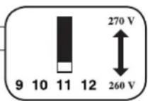
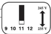
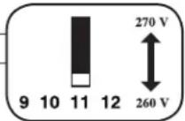
11 Select High AC Input Voltage Point for Switching to Battery - OPTIONAL\*
Voltage Switch Position
| 270 VAC | Up |
| 260 VAC | Down (factory setting) |
208V Operation (APSX6048VRNET model with Switch #4 in "Up" position)
9 10 Select Low VAC Input Voltage Point for Switching to Battery - OPTIONAL\*
Voltage 9, 10 Switch Position
| 175 VAC | Up, Up | 9 | 10 | 11 | 12 |
| 165 VAC | Up, Down | 9 | 10 | 11 | 12 |
| 175 VAC | Down, Up | 9 | 10 | 11 | 12 |
| 165 VAC | Down, Down (factory setting) | 9 | 10 | 11 | 12 |
11 Select High AC Input Voltage Point for Switching to Battery - OPTIONAL\*
Voltage Switch Position
| 245 VAC | Up |
| 235 VAC | Down (factory setting) |
230V Operation (APSX6048VRNET model with Switch #4 in "Down" position)
9 10 Select Low VAC Input Voltage Point for Switching to Battery
Voltage 9, 10 Switch Position
| 180 VAC | Up, Up | 9 | 10 | 11 | 12 |
| 170 VAC | Up, Down | 9 | 10 | 11 | 12 |
| 180 VAC | Down, Up | 9 | 10 | 11 | 12 |
| 170 VAC | Down, Down (factory setting) | 9 | 10 | 11 | 12 |
11 Select High AC Input Voltage Point for Switching to Battery - OPTIONAL\*
Voltage Switch Position
| 270 VAC | Up |
| 260 VAC | Down (factory setting) |
* Most of your connected appliances and equipment will perform adequately when your Inverter/Charger's High AC Input Voltage Point and its Low AC Voltage Input Point is left in the factory setting. However, if the unit frequently switches to battery power due to momentary high/low line voltage swings that would have little effect on equipment operation, you may wish to adjust these settings. By increasing the High AC Voltage Point and/or decreasing the Low AC Voltage Point, you will reduce the number of times your unit switches to battery due to voltage swings.
Configuration
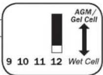
12 Select Battery Type - REQUIRED
CAUTION: The Battery Type DIP Switch setting must match the type of batteries you connect, or your batteries may be degraded or damaged over an extended period of time. See "Battery Selection" for more information.
Battery Type Switch Position
AGM/Gel Cell (Sealed) Battery Up
Wet Cell (Vented) Battery Down (factory setting)
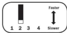
Set Battery Charge Conserver (Load Sense) Control—OPTIONAL
In order to save battery power, the unit's inverter automatically shuts off in the absence of any power demand from connected equipment or appliances (the electrical load). When the Inverter/Charger detects a load, it automatically turns its inverter function on. Users may choose the minimum load the Inverter/Charger will detect by adjusting the Battery Charge Conserver Control (see diagram). Using a flathead screwdriver, turn the control clockwise to lower the minimum load that will be detected, causing the inverter to turn on for smaller loads. When the control is turned fully clockwise, the inverter will operate even when there is no load. Turn the control counterclockwise to increase the minimum load that will be detected, causing the inverter to stay off until the new minimum load is reached.
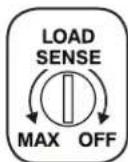
Note: The factory setting for the control is fully clockwise. However, based on the threshold load to which you'd like the inverter to respond, you should adjust the control counterclockwise to reduce its sensitivity until the inverter is active only when connected equipment or appliances are actually in use.
Connect Remote Control—OPTIONAL
The unit features an 8-conductor telephone style jack on the front panel for use with an optional remote control module (Tripp Lite model APSRM4, sold separately). The remote module allows the Inverter/Charger to be mounted in a compartment or cabinet out of sight, while operated conveniently from a remote location. See instructions packed with the remote control module.
Connect Battery Temperature Sensing Cable—OPTIONAL
(Contact Tripp Lite for optional temperature sensing cable accessory.)
The battery temperature sensing function prolongs battery life by adjusting the charge float voltage level based on battery temperature. Connect the sensor cable (the cable has an RJ style connector on one end and a sensor on the other) to the RJ style jack located on the front panel of the Inverter/Charger labeled "RMT BATT TEMP." With user-supplied electrical or duct tape, affix the sensor to the side of the battery below the electrolyte level. Make sure that nothing, not even tape, comes between the sensor and the side of the battery. To guard against false readings due to ambient temperature, place the sensor between batteries, if possible, and away from sources of extreme heat or cold. If the sensor cable is not used, the Inverter/Charger will charge according to its default value (25°C).
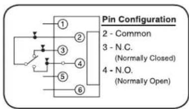
Connect Automatic Generator Starter—OPTIONAL
Connect the RJ type modular jack on the front panel labeled "RMT GEN START" to separate generator ON/OFF switching mechanism with user-supplied cable (see Pin Configuration Diagram). Once attached, the interface will allow the Inverter/Charger to automatically switch a separate generator on when connected battery voltage levels are low and switch it off when battery voltage levels are high.
Note: The operations below apply only to the APSX6048VRNET.
text_image
Pin Configuration 2 - Common 3 - N.C. (Normally Closed) 4 - N.O. (Normally Open)Connect External SNMP/Web Management Module—OPTIONAL
(Contact Tripp Lite for optional external SNMP/Web management module accessory.)
The SNMP/Web management module (Tripp Lite model SNMPWEBSOLOHV) allows the user to remotely monitor and control the inverter/charger. Using the standard serial cable provided with the SNMPWEBSOLOHV, connect one end to the Accessory port on the SNMPWEBSOLOHV labeled "UPS/APS" and the other end to the DB9 serial port located on the front panel of the Inverter/Charger.
Connect 12V DC Power Connector—OPTIONAL
The DC Power Connector enables the SNMPWEBSOLOHV to be powered directly from the Inverter/Charger, eliminating the need for an AC outlet. Connect one end of the cable (included with the SNMPWEBSOLOHV) to the port on the SNMPWEBSOLOHV labeled "DC Power" and connect the other end directly to the Inverter/Charger.
Battery Selection
Select Battery Type
Select “Deep Cycle” batteries to enjoy optimum performance from your Inverter/Charger. Batteries of either Wet-Cell (vented) or Gel-Cell / Absorbed Glass Mat (sealed) construction are ideal. 6-volt “golf cart,” Marine Deep-Cycle or 8D Deep-Cycle batteries are also acceptable. You must set the Inverter/Charger’s Battery Type DIP Switch (see Configuration section for more information) to match the type of batteries you connect or your batteries may be degraded or damaged over an extended period of time.
Match Battery Amp-Hour Capacity to Your Application
Select a battery or system of batteries that will provide your Inverter/Charger with proper DC voltage and an adequate amp-hour capacity to power your application. Even though Tripp Lite Inverter/Chargers are highly efficient at DC-to-AC inversion, their rated output capacities are limited by the total amp-hour capacity of connected batteries plus the output of an alternator when one is used.
Example
• STEP 1) Determine Total Wattage Required
Add the wattage ratings of all equipment you will connect to your Inverter/Charger. Wattage ratings are usually listed in equipment manuals or on nameplates. If your equipment is rated in amps, multiply that number times AC utility voltage to estimate watts. (Example: a drill requires 2.8 amps. 2.8 amps × 230 volts = 640 watts.)
Note: Your Inverter/Charger will operate at higher efficiencies at about 75% - 80% of nameplate rating.
Tools
13mm (1/2") Drill Circular Saw
640W + 800W

=1440W

Appliances and Electronics
Desktop
Computer
Relay with Large
LCD Monitor
Signal
Refrigerator Table Fan
Tower
540W
+ 150W
+ 500W
+ 250W
= 1440W
- STEP 2) Determine DC Battery Amps Required
Divide the total wattage required (from step 1, above) by the nominal battery voltage to determine the DC amps required.
$$ 1 4 4 0 \text { watts } \div 4 8 \mathrm{V} = 3 0 \text { DC Amps } $$
- STEP 3) Estimate Battery Amp-Hours Required
Multiply the DC amps required (from step 2, above) by the number of hours you estimate you will operate your equipment exclusively from battery power before you have to recharge your batteries with utility- or generator-supplied AC power. Compensate for inefficiency by multiplying this number by 1.2. This will give you a rough estimate of how many amp-hours of battery power (from one or several batteries) you should connect to your Inverter/Charger.
Note: Battery amp-hour ratings are usually given for a 20-hour discharge rate. Actual amp-hour capacities are less when batteries are discharged at faster rates. For example, batteries discharged in 55 minutes provide only 50% of their listed amp-hour ratings, while batteries discharged in 9 minutes provide as little as 30% of their amp-hour ratings.
30 DC Amps × 5 Hrs. Runtime
× 1.2 Inefficiency Rating = 180 Amp-Hours
- STEP 4) Estimate Battery Recharge Required, Given Your Application
You must allow your batteries to recharge long enough to replace the charge lost during inverter operation or else you will eventually run down your batteries. To estimate the minimum amount of time you need to recharge your batteries given your application, divide your required battery amp-hours (from step 3, above) by your Inverter/Charger's rated charging amps (23A or 90A, depending on Switch #5 setting).
180 Amp-Hours ÷ 23 Amps
Inverter/Charger Rating = 7.8 Hours Recharge
Battery Connection
Connect your Inverter/Charger to your batteries using the following procedures:
- Connect DC Wiring: Though your Inverter/Charger is a high-efficiency converter of electricity, its rated output capacity is limited by the length and gauge of the cabling running from the battery to the unit. Use the shortest length and largest diameter cabling (maximum 9.3 mm diameter (2/0 AWG)) to fit your Inverter/Charger's DC Input terminals. Shorter and heavier gauge cabling reduces DC voltage drop and allows for maximum transfer of current. Your Inverter/Charger is capable of delivering peak wattage at up to 200% of its rated continuous wattage output for brief periods of time. Heavier gauge cabling should be used when continuously operating heavy draw equipment under these conditions. Tighten your Inverter/Charger and battery terminals to approximately 3.5 Newton-meters of torque to create an efficient connection and to prevent excessive heating at this connection. Insufficient tightening of the terminals could void your warranty.
See table below for recommended cable sizing chart.
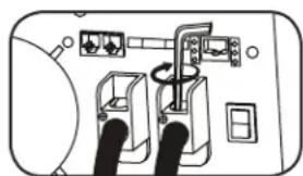
natural_image
Diagram of electrical connections with switches and cables (no text or symbols)DC Connectors
- Connect Fuse: Tripp Lite recommends that you connect your battery to your Inverter/Charger's DC terminals with wiring that includes a fuse and fuse block within 450 mm of the battery. The fuse's rating must equal or exceed the Minimum DC Fuse Rating shown on the Inverter/Charger's nameplate. See diagrams below for proper fuse placement. The battery wire with the fuse should not be grounded.
- Battery Grounding: The Inverter/Charger will operate properly with the battery negative terminal or the battery positive terminal connected to earth ground. It will also operate properly without an earth ground connection to either battery terminal. Any battery ground connection should be made directly from the battery terminal to earth ground.
Maximum Recommended DC Cable Length
| Wire Diameter (Gauge) | |||
| 8.3 mm (0 AWG) 9.3 | mm (2/0 AWG) | ||
| VDC Output Power Maximum Distance from Battery to Unit | |||
| 24V 3000W 13 m (42 ft) 16 m (52 ft) | |||
| 48V 6000W Do not use 32 m (105 ft) | |||

WARNING!
- Follow all applicable electrical codes and requirements for battery grounding.
- Never attempt to operate your Inverter/Charger by connecting it directly to output from an alternator rather than a battery or battery bank.
- Observe proper polarity with all DC connections.
Series Connection
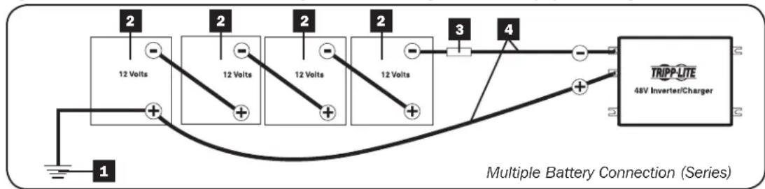
In a series connection, your Inverter/Charger's Nominal DC Input Voltage must match the number of batteries multiplied by their voltage. For example, a 48V DC Inverter/Charger requires either four 12V batteries connected in series (48 = 4 × 12) or eight 6V batteries connected in series (48 = 8 × 6).
Contact Tripp Lite technical support for assistance with additional parallel, series or series/parallel connections.
Figure below illustrates a 48V Inverter/Charger with a negative grounded battery system using 12V batteries.
flowchart
graph LR
    A["12 Volts"] --> B["2"]
    B --> C["3"]
    C --> D["12 Volts"]
    D --> E["2"]
    E --> F["12 Volts"]
    F --> G["2"]
    G --> H["12 Volts"]
    H --> I["4"]
    I --> J["TRIPP-LITE 48V Inverter/Charger"]
    style A fill:#f9f,stroke:#333
    style B fill:#ccf,stroke:#333
    style C fill:#cfc,stroke:#333
    style D fill:#fcc,stroke:#333
    style E fill:#cff,stroke:#333
    style F fill:#ffc,stroke:#333
    style G fill:#cfc,stroke:#333
    style H fill:#fcc,stroke:#333
    style I fill:#ffc,stroke:#333
    style J fill:#fcc,stroke:#333
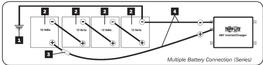
Figure below illustrates a 48V Inverter/Charger with a positive grounded battery system using 12V batteries.
text_image
12 Volts 2 2 2 2 3 4 TRIPP LITE 48V Inverter/Charger Multiple Battery Connection (Series)1 Earth Ground
2 Battery
3 UL-Listed Fuse & Fuse Block (mounted within 450 mm of the battery)
4 Large Diameter Cabling, Maximum 9.3 mm diameter (2/0 AWG) to Fit Terminals
AC Input/Output Connection
To avoid overloading your Inverter/Charger, be sure to match the power requirements of the equipment you plan to run at any one time (add their total watts) with the output wattage capacity of your Inverter/Charger model. When figuring the power requirements of your equipment, do not confuse “continuous” wattage with “peak” wattage ratings. Most electric motors require extra power at start-up (“peak” wattage) than required to run continuously after start-up, sometimes over 100% more. Some motors, such as in refrigerators and pumps, start and stop intermittently according to demand, requiring “peak” wattage at multiple, unpredictable times during operation.
- Cabinet Grounding
Using a 3.15 mm diameter (8 AWG) wire or larger, directly connect the Main Ground Lug to earth ground. See the Feature Identification section to locate the Main Ground Lug on your specific Inverter/Charger model.
• OverPower™ and DoubleBoost™ Features
Tripp Lite Inverter/Chargers deliver up to 150% of their nameplate-rated wattage for 1-60 minutes (OverPower) and up to 200% for 10 seconds (DoubleBoost) under ideal battery and temperature conditions*, providing ample reserve power to support tools and equipment.
* For best results, utilize OverPower for as short a duration as possible, ensure that battery bank and cabling are able to provide full nominal DC voltage under load, and allow the inverter/charger to cool completely before and after OverPower utilization.

Warning! Consult a qualified electrician and follow all applicable electrical codes and requirements for hardwire connection. Disconnect both DC input and AC utility supply before attempting hardwiring. Over-current protection should be provided in accordance with local and/or national electrical codes. Refer to nameplate on unit for input and output current ratings. Use wire with a minimum temperature rating of 90^ C. A readily visible and adequate disconnect device must be provided. Failure to properly ground your Inverter/Charger to earth ground may result in a lethal electrical shock hazard.
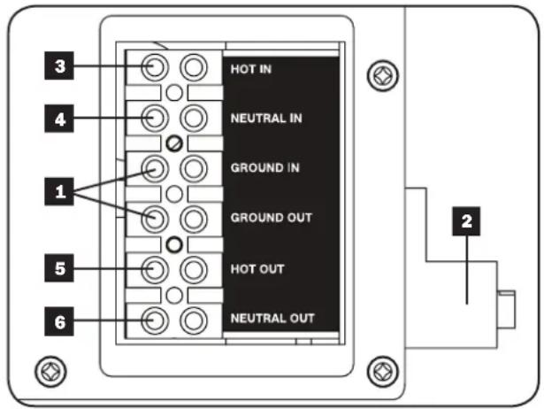
Remove the screws and cover plate over the hardwire terminal strip. Remove the knockout covers closest to the desired electrical source and to your equipment. Attach 13 mm (0.5 inch) diameter conduits (user-supplied) to the knockouts and thread wires through. Connect the conduits to each other with the ground bond connection supplied.
Ground\*
- Connect the incoming and outgoing ground wires to the ground terminals 1.
- Connect the Main Ground Lug 2 to earth ground.
AC Input
- Connect the incoming hot wire to the input hot terminal 3.
- Connect the incoming neutral wire to the input neutral terminal 4.
AC Output
- Connect the outgoing hot wire to the output hot terminal 5.
- Connect the outgoing neutral wire to the output neutral terminal 6.
Replace cover plate and tighten screws.
* If the incoming conduit only contains two wires (hot and neutral), the incoming conduit must be bonded to the main ground lug on the unit. In any case, the incoming conduit must be bonded to earth ground, and the incoming conduit must be bonded to the outgoing conduit.
text_image
3 4 1 5 6 HOT IN NEUTRAL IN GROUND IN GROUND OUT HOT OUT NEUTRAL OUT 2AC Generator Input
The inverter/charger is designed to provide heavy-duty power to both the AC output load and the DC battery charging load at the same time. The amount of additional input power required is determined by the setting of the AC Input Current Sharing DIP switches (switches 7 and 8 - see the Configuration section for switch settings). The recommended minimum VA rating for AC generator input is shown in the table below.
Minimum Recommended AC Generator VA Rating
| AC Input Current Sharing APSX3024SW APSX6048VRNET | |
| Most Limiting 3750VA 7500VA | |
| Less Limiting 4900VA N/A | |
| Least Limiting 6000VA N/A | |
| No Limiting 7200VA N/A |
Note: If the applied AC load is significantly less than that of the Inverter/Charger's AC output rating, a smaller size generator may be used by setting the battery charger DIP Switch to the low DC current setting. The minimum recommended VA rating for the AC generator would then be the VA needed for the Charger (1100 VA for APSX3024SW or 2000 VA for APSX6048VRNET) plus the VA required for the load.
Service
Your Tripp Lite product is covered by the warranty described in this manual. A variety of Extended Warranty and On-Site Service Programs are also available from Tripp Lite. For more information on service, visit www.triplite.com/support. Before returning your product for service, follow these steps:
- Review the installation and operation procedures in this manual to insure that the service problem does not originate from a misreading of the instructions.
- If the problem continues, do not contact or return the product to the dealer. Instead, visit www.tripplite.com/support.
- If the problem requires service, visit www.tripplite.com/support and click the Product Returns link. From here you can request a Returned Material Authorization (RMA) number, which is required for service. This simple on-line form will ask for your unit's model and serial numbers, along with other general purchaser information. The RMA number, along with shipping instructions will be emailed to you. Any damages (direct, indirect, special or consequential) to the product incurred during shipment to Tripp Lite or an authorized Tripp Lite service center are not covered under warranty. Products shipped to Tripp Lite or an authorized Tripp Lite service center must have transportation charges prepaid. Mark the RMA number on the outside of the package. If the product is within its warranty period, enclose a copy of your sales receipt. Return the product for service using an insured carrier to the address given to you when you request the RMA.
Maintenance
Your Inverter/Charger requires no maintenance and contains no user-serviceable or replaceable parts, but should be kept dry at all times. Periodically check, clean and tighten all cable connections as necessary, both at the unit and at the battery.
Troubleshooting
Try these remedies for common Inverter/Charger problems before calling for assistance. Call Tripp Lite Customer Service before returning your unit for service.
| SYMPTOM PROBLEMS CORRECTIONS | ||
| No AC Output (All Indicator Lights Are OFF) | Unit is not properly connected to utility power. Connect unit to utility power. | |
| Operating Mode Switch is set to “OFF” and AC input is present. | Set Operating Mode Switch to “AUTO/REMOTE” or “CHARGE ONLY.” | |
| This is normal when the Operating Mode Switch is set to “CHARGE ONLY” and AC input is absent. | No correction is required. AC output will return when AC input returns. Set Operating Mode Switch to “AUTO/REMOTE” if you require AC output. | |
| Unit has shut down due to battery overcharge (preventing battery damage). The problem may be with connected auxiliary chargers, if any, or with the unit’s charger. | Disconnect any auxiliary chargers. Reset by moving Operating Mode Switch to “OFF.” Wait 1 minute and switch to “AUTO/REMOTE” or “CHARGE ONLY.” If unit remains in shutdown mode after several attempts to reset, contact Tripp Lite Customer Service for assistance. | |
| Unit has shut down due to excessive battery discharge. | Use an auxiliary charger* to raise battery voltage. Check external battery connections and fuse. Unit automatically resets when condition is cleared. | |
| Unit has shut down due to overload. Reduce load. | Reset by moving Operating Mode Switch to “OFF.” Wait 1 minute. Switch to “AUTO/REMOTE” or “CHARGE ONLY.” | |
| Battery Not Recharging (AC Input Present) | Connected batteries are dead. Check and replace old batteries. | |
| Battery fuse* is blown. Check and replace fuse.* | ||
| Battery cabling* is loose. Check and tighten or replace cabling.* | ||
| Unit has shut down due to battery overcharge (preventing battery damage). The problem may be with connected auxiliary chargers, if any, or with the unit’s charger. | Disconnect any auxiliary chargers. Reset by moving Operating Mode Switch to “OFF.” Wait 1 minute and switch to “AUTO/REMOTE” or “CHARGE ONLY.” If unit remains in shutdown mode after several attempts to reset, contact Tripp Lite Customer Service for assistance. | |
| All Three Battery Indicator Lights Are Slowly Flashing (1⁄2 Second Flashes) | Battery is excessively discharged. Use an auxiliary charger* to raise battery voltage. Check external battery connections and fuse. Unit automatically resets when condition is cleared. | |
| All Three Battery Indicator Lights Are Rapidly Flashing (1⁄4 Second Flashes) | Battery is overcharged. Unit will shut down to prevent battery damage. The problem may be with connected auxiliary chargers, if any, or with the unit’s charger. | Disconnect any auxiliary chargers. Reset by moving Operating Mode Switch to “OFF.” Wait 1 minute and switch to “AUTO/REMOTE” or “CHARGE ONLY.” If unit remains in shutdown mode after several attempts to reset, contact Tripp Lite Customer Service for assistance. |
| Red “LOW” Battery Indicator Light is Flashing | Battery voltage is low. Unit will automatically shut down after 10 seconds to protect battery from damage. | Make sure that AC power is present in order to recharge batteries. Reset by moving Operating Mode Switch to “OFF” then to “AUTO/REMOTE” or “CHARGE ONLY.” |
| False reading due to undersized or insufficiently connected DC cabling. | Use sufficient size DC cable sufficiently connected to the Inverter/Charger. | |
| Red “LOAD” Operation Indicator Light Flashing | Inverter is overloaded. Unit will automatically shut down after 5 seconds. | Reduce load. Reset by moving Operating Mode Switch to “OFF.” Wait 1 minute. Switch to “AUTO/REMOTE” or “CHARGE ONLY.” |
*User-supplied.
Warranty
2-Year Limited Warranty
TRIPP LITE warrants its products to be free from defects in materials and workmanship for a period of two (2) years from the date of initial purchase. TRIPP LITE's obligation under this warranty is limited to repairing or replacing (at its sole option) any such defective products. To obtain service under this warranty, you must obtain a Returned Material Authorization (RMA) number from TRIPP LITE or an authorized TRIPP LITE service center. Products must be returned to TRIPP LITE or an authorized TRIPP LITE service center with transportation charges prepaid and must be accompanied by a brief description of the problem encountered and proof of date and place of purchase. This warranty does not apply to equipment, which has been damaged by accident, negligence or misapplication or has been altered or modified in any way.
EXCEPT AS PROVIDED HEREIN, TRIPP LITE MAKES NO WARRANTIES, EXPRESS OR IMPLIED, INCLUDING WARRANTIES OF MERCHANTABILITY AND FITNESS FOR A PARTICULAR PURPOSE.
Some states do not permit limitation or exclusion of implied warranties; therefore, the aforesaid limitation(s) or exclusion(s) may not apply to the purchaser.
EXCEPT AS PROVIDED ABOVE, IN NO EVENT WILL TRIPP LITE BE LIABLE FOR DIRECT, INDIRECT, SPECIAL, INCIDENTAL OR CONSEQUENTIAL DAMAGES ARISING OUT OF THE USE OF THIS PRODUCT, EVEN IF ADVISED OF THE POSSIBILITY OF SUCH DAMAGE. Specifically, TRIPP LITE is not liable for any costs, such as lost profits or revenue, loss of equipment, loss of use of equipment, loss of software, loss of data, costs of substitutes, claims by third parties, or otherwise.

WEEE Compliance Information for Tripp Lite Customers and Recyclers (European Union)
Under the Waste Electrical and Electronic Equipment (WEEE) Directive and implementing regulations, when customers buy new electrical and electronic equipment from Tripp Lite they are entitled to:
- Send old equipment for recycling on a one-for-one, like-for-like basis (this varies depending on the country)
- Send the new equipment back for recycling when this ultimately becomes waste
Regulatory Compliance Identification Numbers
For the purpose of regulatory compliance certifications and identification, your Tripp Lite product has been assigned a unique series number. The series number can be found on the product nameplate label, along with all required approval markings and information. When requesting compliance information for this product, always refer to the series number. The series number should not be confused with the marketing name or model number of the product.
Tripp Lite has a policy of continuous improvement. Specifications are subject to change without notice.
Note on Labeling
Two symbols are used on the APS labels.
V\~: AC Voltage ===: DC Voltage

text_image
TRIPP·LITE
1111 W. 35th Street, Chicago, IL 60609 USA • www.tripplite.com/support
1111 W. 35th Street, Chicago, IL 60609 USA • www.tripplite.com/support
Select Equalize Battery Charge - OPTIONAL
natural_image
Diagram of electrical connections with switches and cables (no text or symbols)Conectores de CC
1111 W. 35th Street, Chicago, IL 60609 USA • www.tripplite.com/support
1111 W. 35th Street, Chicago, IL 60609 USA • www.tripplite.com/support
natural_image
Diagram of a device with two black cables connected to a wall-mounted switch and electrical outlets (no text or symbols visible)DC Connectors
Your Inverter/Charger requires no maintenance and contains no user-serviceable or replaceable parts, but should be kept dry at all times. Periodically check, clean and tighten all cable connections as necessary, both at the unit and at the battery.
Dépannage
1111 W. 35th Street, Chicago, IL 60609 USA • www.tripplite.com/support
(service/maintenance)
1111 W. 35th Street, Chicago, IL 60609 USA • www.tripplite.com/support
natural_image
Diagram of electrical connections with switches and wires (no text or symbols)1111 W. 35th Street, Chicago, IL 60609 USA • www.tripplite.com/support