
ECO550UPS - Inverter Tripp Lite - Free user manual and instructions
Find the device manual for free ECO550UPS Tripp Lite in PDF.


| Product Type | UPS (Uninterruptible Power Supply) with Automatic Voltage Regulation (AVR) |
| Brand | Tripp Lite |
| Model | ECO550UPS |
| Power Capacity | 550 VA / 300 W |
| Input Voltage | 120 V AC (single-phase) |
| Output Voltage | 120 V AC (regulated) |
| Battery Type | Sealed lead-acid, user-replaceable |
| Typical Runtime | Approximately 5-10 minutes at full load |
| Number of Output Outlets | 6 outlets (with surge protection) |
| Telephone/RJ45 Protection | Yes (1 input / 1 output) |
| Coaxial Protection | No |
| Dimensions (W × D × H) | Approximately 31 × 15 × 20 cm |
| Net Weight | Approximately 5.0 kg |
| Noise Level | Silent (fan rarely runs) |
| LED Indicators | LEDs for power failure, low battery, overload |
| AVR Function | Yes (voltage correction without battery) |
| Management Software | PowerAlert (optional via USB port) |
| USB Port | 1 USB port (communication) |
| Maintenance and Cleaning | Dust regularly with a dry cloth; replace battery every 3-5 years. |
| Safety | Protection against surges, short circuits, and overloads. |
| Spare Parts and Repairability | Battery replaceable; other parts to be repaired by a professional. |
Frequently Asked Questions - ECO550UPS Tripp Lite
User questions about ECO550UPS Tripp Lite
0 question about this device. Answer the ones you know or ask your own.
Ask a new question about this device
Download the instructions for your Inverter in PDF format for free! Find your manual ECO550UPS - Tripp Lite and take your electronic device back in hand. On this page are published all the documents necessary for the use of your device. ECO550UPS by Tripp Lite.
USER MANUAL ECO550UPS Tripp Lite
(Series Number: AG-0306, AG-0310, AG-0313, AG-0315, AG-0316, AG-0318, AG-0319)
natural_image
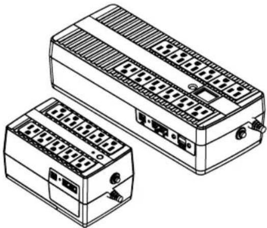
Line drawing of two electronic device modules with ventilation grilles and ports (no text or symbols)Español 21 • Français 41
WARRANTY REGISTRATION
Register your product today and be automatically entered to win an ISOBAR® surge protector in our monthly drawing!

tripplite.com/warranty


1111 W. 35th Street, Chicago, IL 60609 USA • tripplite.com/support
Copyright © 2020 Tripp Lite. All rights reserved.
Table of Contents
Important Safety Instructions 3
Quick Installation (All Models) 5
Basic Operation for Models with an LED Interface 8
(ECO350UPS, ECO550UPS, ECO650UPSM, ECO750UPS, ECO900UPSM)
Basic Operation for Models with an LCD Panel 11
(ECO850LCD, ECO900LCDU2)
UPS Features 15
Battery Replacement 17
Storage and Service 18
Specifications
Product Registration 19
Regulatory Compliance 19
18
Important Safety Instructions
SAVE THESE INSTRUCTIONS
This manual contains instructions and warnings that should be followed during the installation, maintenance and storage of the UPS and batteries. Failure to heed these warnings may affect the warranty.
UPS Location Warnings
- Install your UPS indoors, away from excess moisture or heat, conductive contaminants, dust or direct sunlight.
- For best performance, keep the indoor temperature between 32irc F and 104irc F ( 0irc C and 40irc C).
- Leave adequate space around all sides of the UPS for proper ventilation.
- Optional mounting: The UPS may be securely mounted in a horizontal or vertical position. To mount, use two screws (not provided) to secure the UPS rear keyholes to a flat surface.
UPS Connection Warnings
- Connect your UPS directly to a properly-grounded AC power outlet. Do not plug the UPS into itself; this will damage the UPS.
- Do not modify the UPS plug, and do not use an adapter that would eliminate the UPS ground connection.
- Do not use extension cords to connect the UPS to an AC outlet.
- If the UPS receives power from a motor-powered AC generator, the generator must provide clean, filtered, computer-grade output.
- The mains socket outlet that supplies the UPS should be easily accessible and located near the UPS.
Equipment Connection Warnings

Install in accordance with National Electrical Code standards ANSI/NFPA 70 and Canadian Electrical Code, Part I, C22.1.
Short-circuit backup protection and overcurrent protection is provided by the building installation.
To reduce the risk of fire, connect only to a circuit with a maximum 20A provided branch circuit overcurrent protection in accordance with the National Electrical Code, ANSI/NFPA 70 and the Canadian Electrical Code, Part I, C22.1. The plug on the power supply cord is intended to serve as the disconnect device. Be sure that the socket-outlet is installed near the equipment and is made easily accessible.
The UPS is intended for use on a TN power distribution system.
Important Safety Instructions
- Use of this equipment in life support applications where failure of this equipment can reasonably be expected to cause the failure of the life support equipment or to significantly affect its safety or effectiveness is not recommended.
- Do not connect surge protectors or extension cords to the output of your UPS. This might damage the UPS and may affect the surge protector and UPS warranties.
- Connect the UPS to an outlet that is adequately protected against excess currents, short circuits and earth faults as part of the building installation.
Battery Warnings
- Batteries can present a risk of electrical shock and burn from high short-circuit current. Observe proper precautions. There are no user-serviceable parts inside the UPS. Do not open the UPS except to perform battery replacement. Do not open batteries. Do not short or bridge the battery terminals with any object. Released material is harmful to the skin and eyes. It may be toxic. Unplug and turn off the UPS before performing battery replacement. Use tools with insulated handles. Battery replacement should be performed only by authorized service personnel using the same number and type of batteries (sealed lead-acid). Do not dispose of the batteries in a fire. Tripp Lite offers a complete line of UPS System Replacement Battery Cartridges (R.B.C.). Visit Tripp Lite on the Web at tripplite.com/products/battery-finder to locate the specific replacement battery for your UPS.

CAUTION: A battery can present a risk of electrical shock and high short-circuit current. Contact with any part of a grounded battery can result in electrical shock. The following precautions should be observed when working on batteries:
- Remove watches, rings or other metal objects.
- Use tools with insulated handles.
- Wear rubber gloves.
- Do not lay tools or metal parts on top of batteries.
- Disconnect charging source and load prior to installing or maintaining the battery.
- Remove battery grounds during installation and maintenance to reduce likelihood of shock.
- Remove the connection from ground if any part of the battery is determined to be grounded.
UPS and Battery Recycling

Tripp Lite products use sealed lead-acid batteries, which are highly recyclable.
Call Tripp Lite at 1.773.869.1234 or visit tripplite.com/support/recycling-program for more information on recycling the batteries or any other Tripp Lite product. Please refer to local codes for disposal requirements.
Quick Installation (All Models)
STEP 1: Plug the UPS into a properly grounded outlet.
After plugging the UPS into a wall outlet, the surge only outlets will begin passing power.
Note: The UPS will not turn on automatically in the presence of live utility power.
STEP 2: Plug your equipment into the UPS.
There are two sets of outlets on your UPS. Outlets marked SURGE ONLY / do not provide battery backup power during power outages. Connect common desktop items like printers, scanners and other accessories not requiring battery support to these outlets. Outlets marked BATTERY BACKUP / offer UPS battery backup support during power failures. Connect your vital computer equipment into these outlets.
Your UPS is designed to support electronic equipment only. You will overload the UPS if the total volt-amp (VA) ratings for all the equipment connected to the BATTERY BACKUP / 📄 outlets exceed the UPS output capacity. To find your equipment's VA ratings, look on their nameplates. If the equipment is listed in amps (A), multiply the number of amps by 120 to determine VA. For example: 1A × 120 = 120VA. If you suspect you have overloaded the outlets, remove some equipment.
STEP 3: Turn the UPS on.
Press and hold the power switch next to the status LED or LCD screen until the alarm begins to sound, then release.
The UPS alarm will sound twice as the battery backup outlets begin passing power and the UPS charger engages as necessary to keep batteries fully charged.
Your UPS is now ready to protect equipment connected to the battery backup outlets from blackouts, brownouts, overvoltages and power failures.

natural_image
Line drawing of a hand inserting a plug into an electrical outlet (no text or symbols)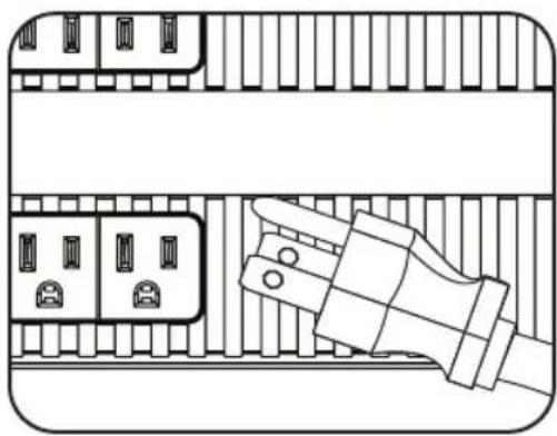
natural_image
Diagram of a hand inserting into a connector socket (no text or symbols)
Quick Installation (All Models)
If you experience LED/LCD issues when turning on your UPS, please refer to the table below:
| Models Problem Solution (All Models) | ||
| ECO350UPS, ECO550UPS, ECO650UPSM (1 LED) | The PROTECTED LED does not illuminate when the UPS is turned ON. | 1. Make sure the UPS is plugged into a live AC outlet.2. Press and hold the power button to turn on the UPS. A beep should sound when the UPS starts.3. If the UPS still does not start, contact Tripp Lite Tech Support for assistance. |
| ECO750UPS, ECO900UPSM (3 LEDs) | The PROTECTED LED does not illuminate when the UPS is turned ON. | |
| ECO850LCD, ECO900LCDU2 (LCD Panel) | The LCD panel does not illuminate for 20 seconds when the UPS is first turned on. | |
Optional Installation
Both UPS models include USB communication ports and tel/DSL/Ethernet surge protection jacks (not compatible with PoE applications). These connections are optional, as the UPS will work properly without these connections.

natural_image
Diagram of a device setup with monitor, cable, and ports (no text or labels)Quick Installation (All Models)
ECO Energy Saving
The ECO Energy Saving feature allows your UPS system to save energy by automatically turning off designated outlets when your computer or other item connected to the “MASTER” outlet is turned off or in standby mode. The ECO feature is disabled by default.
To enable ECO Energy Saving:
1 Connect nonessential devices that you would like to be automatically powered OFF and ON to the “CONTROLLED BY MASTER OUTLET” receptacles. Make sure that any devices connected to these outlets can be powered off automatically without interrupting your internet connection, local network or other essential services.
2 Select the device from your equipment configuration, such as a desktop computer, AV receiver or other vital component and connect its power cord to the designated "MASTER" outlet on the UPS. This master device will serve as the trigger to automatically power-on all equipment connected to "CONTROLLED BY MASTER OUTLET" receptacles whenever the device connected to the "MASTER" outlet is powered-on. When the device connected to the "MASTER" outlet is turned off or enters a low-power sleep mode, devices connected to the "CONTROLLED BY MASTER OUTLET" receptacles will automatically be powered off.
3 To enable ECO energy-saving mode, double-click the UPS power button while the UPS is turned on and running from utility power. The UPS confirms ECO mode is engaged via the LED or LCD interface:
- On single LED models, the green LED flashes off every 10 seconds
- On 3 LED models, the green LED to the left of the PROTECTED LED will flash off every 10 seconds
- On LCD equipped models, the display will report ECO when the ECO status screen is activated
4 Once ECO energy-saving mode is enabled, the UPS will automatically turn OFF all devices connected to the “CONTROLLED BY MASTER OUTLET” receptacles approximately 3 minutes after the device connected to the “MASTER” outlet is turned off or enters a low-power sleep mode. (The 3 minute delay ensures the controlled outlets remain powered ON during a reboot). Devices connected to “CONTROLLED BY MASTER OUTLET” receptacles are automatically powered ON when the device connected to the “MASTER” outlet is powered back on.
Note: A minimum load is required on the “MASTER” outlet in order for controlled outlets to power ON, as stated in the table below.
| Model Required Load | |
| EC0350UPS 15W | |
| EC0550UPS 21W | |
| EC0650UPSM 23W | |
| EC0750UPS 23W | |
| EC0850LCD 21W | |
| EC0900UPSM 24W | |
| EC0900LCDU2 24W |
Quick Installation (All Models)
To disable ECO Energy Saving:
Double-click the UPS power button while the UPS is turned on and running from utility power. The UPS confirms ECO mode is OFF via the LED or LCD interface:
- On single LED models, the green LED will be lighted continuously
- On 3 LED models, the green LED to the left of the PROTECTED LED will be lighted continuously
- On LCD equipped models, the display will report ECO when the ECO status screen is off
Note: The “CONTROLLED BY MASTER OUTLET” receptacles available on the “SURGE ONLY” bank of outlets provide surge and noise suppression only, they do not provide battery backup. During a power failure, these outlets will be off regardless of whether the ECO energy-saving feature is enabled or disabled. Select models include one battery-backup supported “CONTROLLED BY MASTER OUTLET” receptacle.
Basic Operation
for Models with an LED Interface (ECO350UPS, ECO550UPS, ECO650UPSM, ECO750UPS, ECO900UPSM)
UPS ON/OFF
- Plug the UPS into a live, grounded outlet: The SURGE ONLY outlets will begin passing power.
- Plug equipment into the UPS: You will overload the UPS if the total volt-amp (VA) ratings for all the equipment connected to the BATTERY BACKUP outlets exceed the UPS output capacity. To find your equipment's VA ratings, look on their nameplates. If the equipment is listed in amps (A), multiply the number of amps by 120 to determine VA. For example: 1A × 120 = 120VA .
- Turn the UPS on: Press and hold the power button next to the STATUS LEDs. The UPS alarm will beep once briefly and the left-side green LED will illuminate. The BATTERY BACKUP outlets will begin passing AC line power. The UPS will automatically recharge internal batteries as needed. Once turned on, your UPS is ready to protect connected equipment from blackouts, brownouts, overvoltages and transient surges.
- Turn the UPS off: Press and hold the power button next to the STATUS LEDs.
Note: UPS system will function properly upon initial startup; however, maximum runtime for the unit's battery will only be accessible after it has been charged for 24 hours.
Basic Operation
for Models with an LED Interface (ECO350UPS, ECO550UPS,
ECO650UPSM, ECO750UPS, ECO900UPSM)
1 LED Indicator
(ECO350UPS, ECO550UPS, ECO650UPSM Models)

PROTECTED
| Description | Green “PROTECTED” LED | Alarm |
| Line Mode | On (flashes off every 3 seconds if ECO Energy Saving feature enabled) | Off |
| Battery Mode On, | flashes off every 10 seconds | Off |
| Battery Low On, | flashes off every 1 second | Sounds every 1 second |
| Line Mode Overload Alert* | On | Sounds every 0.5 second |
| Line Mode Overload Fault* | Off | Sounds continuously |
| Battery Mode Overload Alert** | Flashes | Sounds every 0.5 second |
| Battery Mode Overload Fault** | Off | UPS will shut down |
| Replace Battery On | Sounds every 1 minute | |
| Fault Condition Off | Sounds continuously |
*Line Mode Overload Alert Condition - 110%±10%, goes to fault after 5 minutes; Overload Fault Condition - 120%±10%, goes to fault immediately
**Battery Mode Overload Alert Condition - 110%±10%, shuts down in 5 seconds; Battery Mode Overload Fault Condition - 120%±10%, shuts down immediately
Basic Operation
for Models with an LED Interface (ECO350UPS, ECO550UPS,
ECO650UPSM, ECO750UPS, ECO900UPSM)
3 LED Indicators (ECO750UPS, ECO900UPSM Models)
PROTECTED

natural_image
Three circular icons with different symbols: a simple wavy line, a white circle, and a warning triangle (no text or labels)| Description Green LED 1 Green LED 2 Red LED Alarm | ||||
| Line Mode On On | Off Off | |||
| Battery Mode Off | On (flashes OFF every 10 seconds) | Off Off | ||
| Battery Low Off | On (flashes every 1 second) | On | Sounds every 1 second | |
| Line Mode Overload Alert* | On On Off | Sounds every 0.5 second | ||
| Line Mode Overload Fault* | Off Off On | Sounds continuously | ||
| Battery Mode Overload Alert** | Off Flashes | Off | Sounds every 0.5 second | |
| Battery Mode Overload Fault** | Off Off Off | Off | ||
| Replace Battery On | On | Flashes on every 1 minute | Sounds every 1 minute | |
| Fault Condition Off | Off On | Sounds continuously | ||
*Line Mode Overload Alert Condition - 110%±10%, goes to fault after 5 minutes; Overload Fault Condition - 120%±10%, goes to fault immediately.
**Battery Mode Overload Alert Condition - 110%±10%, shuts down in 5 seconds; Battery Mode Overload Fault Condition - 120%±10%, shuts down immediately.
Basic Operation
for Models with an LCD Panel (ECO850LCD, ECO900LCDU2)
UPS ON/OFF
- Plug the UPS into a live, grounded outlet.
The LCD panel will illuminate and the battery charger will engage as necessary. The SURGE-PROTECTED outlets will begin passing power. - Plug equipment into the UPS: You will overload the UPS if the total volt-amp (VA) ratings for all the equipment connected to the BATTERY/SURGE PROTECTED outlets exceed the UPS output capacity. To find your equipment's VA ratings, look on their nameplates. If the equipment is listed in amps (A), multiply the number of amps by 120 to determine VA. For example: 1A × 120 = 120VA .
- Turn the UPS on: Press and hold the power button. The alarm will beep twice. The BATTERY/SURGE PROTECTED outlets will begin passing AC line power. The UPS will automatically recharge internal batteries as needed. Once turned on, your UPS is ready to protect connected equipment from blackouts, brownouts, overvoltages and transient surges.
- Turn the UPS off: Press and hold the power button until a beep is heard, then release.
Note: UPS system will function properly upon initial startup; however, maximum runtime for the unit's battery will only be accessible after it has been charged for 24 hours.
Basic Operation
for Models with an LCD Panel (ECO850LCD, ECO900LCDU2)
LCD Panel

On-Line AC Power Mode LCD Data
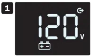
The LCD touchscreen offers 6 screens of UPS and site power information when the UPS is operating in line power mode. Screens 1-5 (Output voltage, Input voltage, Load %, Battery charge % and ECO mode off/on status) are available for viewing in line power mode. Press the front panel LCD to advance to the next screen. Screen 6 (Overload) is displayed automatically only when the UPS is loaded to levels greater than 100%.

1 Output Voltage
2 Input Voltage
3 Load %
4 Battery Charge Level
5 ECO On/Off
6 Overload
Note: The touchscreen LCD display automatically turns-off in line power mode 20 seconds after it was last touched. To re-activate the LCD for an additional 20 seconds, touch the screen.
Basic Operation
for Models with an LCD Panel (ECO850LCD, ECO900LCDU2)
| Operating Mode Alarm Description | ||
| Battery Mode Normal | Normal No Alarm | |
| Battery Low Sounds Every Second | ||
| Overload Sounds Every 0.5 | Second | |
| Line Mode Normal | No Alarm | |
| Overload Sounds Every 0.5 | Second | |
| Battery Replace Sounds Every Minute | ||
| Fault Mode Sounds Continuously | ||
Battery Power Mode LCD Data
The LCD touchscreen offers 6 screens of UPS and site power information when the UPS is operating in battery power mode. Screens 1-5 (Output voltage, Input voltage, Load %, Battery charge % and ECO mode off/on status) are available for viewing in line power mode. Press the front panel LCD to advance to the next screen. Screen 6 (Overload) is displayed automatically only when the UPS is loaded to levels greater than 100%.


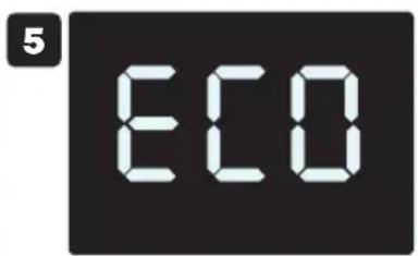

1 Output Voltage
2 Input Voltage
3 Load %
4 Battery Charge Level
5 ECO On/Off
6 Overload
Note: The touchscreen LCD display will remain ON continuously during battery mode operation.
Basic Operation
for Models with an LCD Panel (ECO850LCD, ECO900LCD2U)
Critical Fault Screens


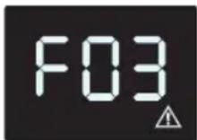


| Error Code Critical Fault Solution | ||
| F01 OUTPUT SHORT Disconnect load(s) from UPS outlets. Power off UPS and contact Tripp Lite Technical Support for assistance. | ||
| F02 OVERLOAD Remove excess load, check load meter on LCD for load status. | ||
| F03 OVERCHARGE Turn unit off, unplug UPS and contact Tripp Lite Technical Support for assistance. | ||
| F04 BATTERY LOW VOLTAGE | Charge UPS for 24 hours. If problem persists, replace battery and contact Tripp Lite Technical Support. | |
| F05 BATTERY MODE HIGH OUTPUT | Turn off power to the UPS and contact Tripp Lite Technical Support for assistance. | |
UPS Features
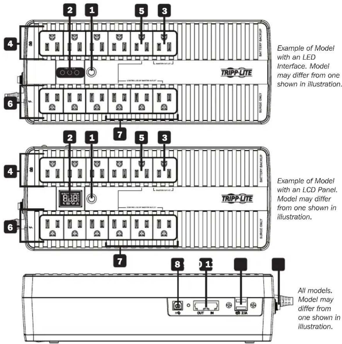
1 ON/OFF Button: When the UPS is on, press and release this button after one beep to turn the UPS off.
2 LED Interface/LCD Panel: Provides current status of the UPS.
- For a detailed description of LEDs, refer to "LED Indicator(s)" in the Basic Operation for Models with an LED Interface section.
- For a detailed description of the LCD panel, refer to "LCD Panel" in the Basic Operation for Models with an LCD Panel section.
3 "Master" Outlet: The device connected to the battery-supported Master Outlet determines the OFF/ON power status of the designated "Controlled by Master Outlet" receptacles (5 and 7) whenever the ECO ECO Energy Saving feature is enabled.
For more information, refer to "ECO Energy Saving" in the Quick Installation section.
UPS Features
4 Battery Backup/Surge Protected Outlets: These battery-supported outlets offer complete UPS battery backup and surge suppression for vital system components requiring continuous power.
5 "Controlled By Master Outlet" UPS Supported Receptacles (available on select models only): This battery-supported outlet has the option for automatic OFF/ON power control in response to the power consumption status of the device connected to the Master Outlet when the ECO feature is enabled. For more information, refer to "ECO Energy Saving" in the Quick Installation section.
6 Surge Protected Outlets: These outlets offer premium surge suppression only. Devices connected to these outlets will not receive battery backup during power failures.
7 "Controlled By Master Outlet" Surge-Only Receptacles: These outlets have the option for automatic OFF/ON power control in response to power consumption of the device connected to the Master Outlet whenever the ECO feature is enabled. For more information, refer to "ECO Energy Saving" in the Quick Installation section.
8 USB Communication Port: This port can connect your UPS to any computer for automatic file saving and unattended shutdown in the event of a power failure. Use with Tripp Lite's PowerAlert® Software (available as a FREE download at triplite.com) and the USB cable included with your UPS. This connection is optional, your UPS will work properly without it.
Note: This UPS System provides basic communication compatibility with most integrated Windows ® , Macintosh ® and Linux ® power management applications.
9 Tel/DSL/Ethernet Line Protection Jacks: These jacks protect equipment against surges over a single phone line or network connection. Connecting your equipment to these jacks is optional; your UPS will work properly without this connection.
Note: Not compatible with PoE (Power over Ethernet) applications.
10 USB Charging Port (available on select models only): The USB charging ports deliver 5V DC charge current for use with most cell phones, smartphones, MP3 players and other devices that are compatible with USB chargers.
Note: This port is intended for USB charging only. USB communication is not accessible through this port. USB charging is only available when the UPS is on and receiving utility power.
11 Resettable Input Circuit Breaker: Protects your electrical circuit from overcurrent draw from the UPS load. If this breaker trips, remove some of the load, then reset by pressing it in.
Battery Replacement
Under normal conditions, the original battery in your UPS will last several years. Battery replacement should only be performed by qualified personnel. Refer to “Battery Warnings” in the Important Safety Instructions section for more information.
| Model Battery Replacement Type | |
| ECO350UPS DJW12-2.8 | |
| ECO550UPS SHR3.6-12 | |
| ECO650UPSM SHR3.6-12 | |
| ECO750UPS | 12VDC, 7Ah |
| ECO850LCD 12VDC, 7Ah | |
| ECO900UPSM 12VDC, 7Ah | |
| ECO900LCDU2 12VDC, 7Ah |
For further information about replacement compatibility and ordering, visit tripplite.com/products/battery-finder.

Battery replacement must be done using the same battery type and quantity: 12V DC sealed lead-acid, 6-cell and in compliance with UL 1989.

CAUTION: Risk of energy hazard. Before replacing batteries, remove conductive jewelry such as chains, wristwatches and rings. High energy passing through conductive materials may cause severe burns.

Caution: Risk of explosion if battery is replaced by an incorrect battery type. Dispose of used batteries according to the instructions.
Storage and Service
Storage
To avoid battery drain, all connected equipment should be turned off and disconnected from the UPS. Press and hold the power button next to the STATUS LEDs and disconnect the unit from AC power. Your UPS will be completely turned off (deactivated), and will be ready for storage. If you plan on storing your UPS for an extended period, fully recharge the UPS batteries every three months. Plug the UPS into a live AC outlet and allow the batteries to recharge for 4 to 6 hours. If you leave your UPS batteries discharged for a long period of time, they will suffer a permanent loss of capacity.
Service
A variety of Extended Warranty and On-Site Service Programs are available from Tripp Lite. For more information on service, visit tripplite.com/support.
Before returning your product for service, follow these steps:
- Review the installation and operation procedures in this manual to ensure that the service problem does not originate from a misreading of the instructions.
- If the problem continues, do not contact or return the product to the dealer. Instead, visit tripplite.com/support.
- If the problem requires service, visit tripplite.com/support and click the Product Returns link. From here you can request a Returned Material Authorization (RMA) number, which is required for service. This simple on-line form will ask for your unit's model and serial numbers, along with other general purchaser information. The RMA number, along with shipping instructions, will be emailed to you. Any damages (direct, indirect, special or consequential) to the product incurred during shipment to Tripp Lite or an authorized Tripp Lite service center is not covered under warranty. Products shipped to Tripp Lite or an authorized Tripp Lite service center must have transportation charges prepaid. Mark the RMA number on the outside of the package. If the product is within its warranty period, enclose a copy of your sales receipt. Return the product for service using an insured carrier to the address given to you when you request the RMA.
Specifications
| Model ECO350UPS | ECO550UPS | ECO650UPSM | ECO750UPS | ECO850LCD | ECO900LCDU2 | ECO900UPSM | |
| Nominal voltage and input range | 120V~, 95-145V | 120V~, 95-145V | 120V~, 95-145V | 120V~, 95-145V | 120V~, 95-145V | 120V~, 95-145V | 120V~, 95-145V |
| Nominal input frequency and tolerance | 50/60 Hz (+/- 5 Hz) | 50/60 Hz (+/- 5 Hz) | 50/60 Hz (+/- 5 Hz) | 50/60 Hz (+/- 5 Hz) | 50/60 Hz (+/- 5 Hz) | 50/60 Hz (+/- 5 Hz) | 50/60 Hz (+/- 5 Hz) |
| Nominal output voltage | 120V~ in line mode and 120V~ in battery | 120V~ in line mode and 120V~ in battery | 120V~ in line mode and 120V~ in battery | 120V~ in line mode and 120V~ in battery | 120V~ in line mode and 120V~ in battery | 120V~ in line mode and 120V~ in battery | 120V~ in line modeand 120V~ in battery |
| Nominal output frequency | 50/60 Hz (+/- 0.5 Hz) | 50/60 Hz (+/- 0.5 Hz) | 50/60 Hz (+/- 0.5 Hz) | 50/60 Hz (+/- 0.5 Hz) | 50/60 Hz (+/- 0.5 Hz) | 50/60 Hz (+/- 0.5 Hz) | 50/60 Hz (+/- 0.5 Hz) |
| Output voltage regulation in line mode | 120 V~ (+6% / -12%) | 120 V~ (+6% / -12%) | 120 V~ (+6% / -12%) | 120 V~ (+6% / -12%) | 120 V~ (+6% / -12%) | 120 V~ (+6% / -12%) | 120 V~ (+6% / -12%) |
| Output voltage regulation in battery mode | 120 V~ (+/-10%) | 120 V~ (+/-10%) | 120 V~ (+/-10%) | 120 V~ (+/-10%) | 120 V~ (+/-10%) | 120 V~ (+/-10%) | 120 V~ (+/-10%) |
Specifications
| Model ECO350UPS | ECO550UPS | ECO650UPSM | ECO750UPS | ECO850LCD | ECO900LCDU2 | ECO900UPSM | |
| Nominal output power in W / VA | 210W / 350VA 3 | 300W / 500VA 325W | W / 650VA 450W / 750VA | 750VA | 425W / 850VA | 480W / 900VA 480W / 900VA | 480W / 900VA |
| Output voltage waveform | Sinusoidal in line mode and quasi-sine (PWM) in battery mode | Sinusoidal in line mode and quasi-sine (PWM) in battery mode | Sinusoidal in line mode and quasi-sine (PWM) in battery mode | Sinusoidal in line mode and quasi-sine (PWM) in battery mode | Sinusoidal in line mode and quasi-sine (PWM) in battery mode | Sinusoidal in line mode and quasi-sine (PWM) in battery mode | Sinusoidal in line mode and quasi-sine (PWM) |
| Maximum output current @ P.F. | 2.9A @ 120V~ | 4.6A @ 120V~ | 5.4A @ 120V~ | 6.3A @ 120V~ | 7.1A @ 120V~ | 7.5A @ 120V~ | 7.5A @ 120V~ |
| Efficiency with nominal load | 95% 95% 95% 95% | 95% 95% 95% 95% | |||||
| Maximum operating altitude at 100% of nominal power | 6562 ft. (2000 m) | 6562 ft. (2000 m) | 6562 ft. (2000 m) | 6562 ft. (2000 m) | 6562 ft. (2000 m) | 6562 ft. (2000 m) | 6562 ft. (2000 m) |
| Online Overload Capability | 110% +/- 10% @ 5 minutes | 110% +/- 10% @ 5 minutes | 110% +/- 10% @ 5 minutes | 110% +/- 10% @ 5 minutes | 110% +/- 10% @ 5 minutes | 110% +/- 10% @ 5 minutes | 110% +/- 10% @ 5 minutes |
| Overload capacity in battery mode | 110% +/- 10% @ 5 seconds | 110% +/- 10% @ 5 seconds | 110% +/- 10% @ 5 seconds | 110% +/- 10% @ 5 seconds | 110% +/- 10% @ 5 seconds | 110% +/- 10% @ 5 seconds | 110% +/- 10% @ 5 seconds |
| Current limitation | 5A @ 120V-- 10A | 120V-- 10A @ 120V-- | 120V-- 10A @ 120V-- | 10A @ 120V-- | 10A @ 120V-- | 10A @ 120V-- | 10A @ 120V-- |
| Autonomy time at full load | 2 minutes @ 210W | 1.2 minutes @ 300W | 1 minute @ 325W | 2 minutes @ 450W | 2.3 minutes @ 425W | 1.7 minutes @ 480W | 1.7 minutes @ 480W |
| Battery recharge time | 6.5 hours to 90% | 6.5 hours to 90% | 6.5 hours to 90% | 6.5 hours to 90% | 8 hours to 90% | 8 hours to 90% | 8 hours to 90% |
| Transfer time 6 milliseconds typical (10 milliseconds max) | 6 milliseconds typical (10 milliseconds max) | 6 milliseconds typical (10 milliseconds max) | 6 milliseconds typical (10 milliseconds max) | 6 milliseconds typical (10 milliseconds max) | 6 milliseconds typical (10 milliseconds max) | 6 milliseconds typical (10 milliseconds max) | 6 milliseconds typical (10 milliseconds max) |
| Outlets 3x 5-15R | outlets with battery backup and surge; 3x 5-15R outlets surge only | 5x 5-15R outlets with battery backup and surge; 5x 5-15R outlets surge only | 5x 5-15R outlets with battery backup and surge; 5x 5-15R outlets surge only | 6x 5-15R outlets with battery backup and surge; 6x 5-15R outlets surge only | 6x 5-15R outlets with battery backup and surge; 6x 5-15R outlets surge only | 6x 5-15R outlets with battery backup and surge; 6x 5-15R outlets surge only | 6x 5-15R outlets with battery backup and surge; 6x 5-15R outlets surge only |
| Maximum input current | 5A @ 120V~ 10A | 120V~ 10A @ 120V~ | 120V~ 10A @ 120V~ | 10A @ 120V~ | 10A @ 120V~ | 10A @ 120V~ | 10A @ 120V~ |
Product Registration
Visit tripplite.com/warranty today to register your new Tripp Lite product. You'll be automatically entered into a drawing for a chance to win a FREE Tripp Lite product!*
* No purchase necessary. Void where prohibited. Some restrictions apply. See website for details.
Regulatory Compliance
FCC Part 68 Notice (United States Only)
If your Modem/Fax Protection causes harm to the telephone network, the telephone company may temporarily discontinue your service. If possible, they will notify you in advance. If advance notice isn't practical, you will be notified as soon as possible. You will be advised of your right to file a complaint with the FCC. Your telephone company may make changes in its facilities, equipment, operations or procedures that could affect the proper operation of your equipment. If it does, you will be given advance notice to give you an opportunity to maintain
Regulatory Compliance
uninterrupted service. If you experience trouble with this equipment's Modem/Fax Protection, please visit tripplite.com/support for repair/warranty information. The telephone company may ask you to disconnect this equipment from the network until the problem has been corrected or you are sure the equipment is not malfunctioning. There are no repairs that can be made by the customer to the Modem/Fax Protection. This equipment may not be used on coin service provided by the telephone company. Connection to party lines is subject to state tariffs. (Contact your state public utility commission or corporation commission for information.)
FCC Notice, Class B
This device complies with part 15 of the FCC Rules. Operation is subject to the following two conditions: (1) This device may not cause harmful interference, and (2) this device must accept any interference received, including interference that may cause undesired operation.
Note: This equipment has been tested and found to comply with the limits for a Class B digital device, pursuant to part 15 of the FCC Rules. These limits are designed to provide reasonable protection against harmful interference in a residential installation. This equipment generates, uses and can radiate radio frequency energy and, if not installed and used in accordance with the instructions, may cause harmful interference to radio communications. However, there is no guarantee that interference will not occur in a particular installation. If this equipment does cause harmful interference to radio or television reception, which can be determined by turning the equipment off and on, the user is encouraged to try to correct the interference by one or more of the following measures:
- Reorient or relocate the receiving antenna.
- Increase the separation between the equipment and receiver.
- Connect the equipment into an outlet on a circuit different from that to which the receiver is connected.
- Consult the dealer or an experienced radio/TV technician for help.
Any changes or modifications to this equipment not expressly approved by Tripp Lite could void the user's authority to operate this equipment.
Equipment Attachment Limitations (models with the Industry Canada label in Canada only)
NOTICE: The Industry Canada label identifies certified equipment. This certification means that the equipment meets the telecommunications network protective, operational and safety requirements as prescribed in the appropriate Terminal Equipment Technical Requirements Document(s). The Department does not guarantee the equipment will operate to the user's satisfaction. Before installing this equipment, users should ensure that it is permissible to be connected to the facilities of the local telecommunications company. The equipment must also be installed using an acceptable method of connection. The customer should be aware that the compliance with the above conditions might not prevent degradation of service in some situations.
Repairs to certified equipment should be coordinated by a representative designated by the supplier. Any repairs or alterations made by the user to this equipment, or equipment malfunctions, may give the telecommunications company cause to request the user to disconnect the equipment.
Users should ensure for their own protection that the electrical ground connections of the power utility, telephone lines and internal metallic water pipe system, if present, are connected together. This precaution may be particularly important in rural areas. Caution: Users should not attempt to make connections themselves, but should contact the appropriate electric inspection authority, or electrician, as appropriate.
Regulatory Compliance Identification Numbers
For the purpose of regulatory compliance certifications and identification, your Tripp Lite product has been assigned a unique series number. The series number can be found on the product nameplate label, along with all required approval markings and information. When requesting compliance information for this product, always refer to the series number. The series number should not be confused with the marking name or model number of the product.
Tripp Lite has a policy of continuous improvement. Product specifications are subject to change without notice.
Note on Labeling Two symbols are used on the label. V\~ : AC Voltage V÷ DC Voltage


1111 W. 35th Street, Chicago, IL 60609 USA • tripplite.com/support
20-08-195 93-38D5_RevB
(Número de Serie: AG-0306, AG-0310, AG-0313, AG-0315, AG-0316, AG-0318, AG-0319)

natural_image
Line drawing of two electronic device enclosures with ports and connectors (no text or symbols)English 1 • Français 41


1111 W. 35th Street, Chicago, IL 60609 EE UU • tripplite.com/support
natural_image
Line drawing of a power outlet with two socket plugs and a plug inserted (no text or symbols)
natural_image
Diagram of a connector with slots and connectors, no text or symbols presentnatural_image
Diagram of a device setup with monitor, cable, and ports (no text or symbols)natural_image
Three circular icons with different symbols: a wavy line, a solid circle, and a warning triangle (no text or labels)1111 W. 35th Street, Chicago, IL 60609 EE UU • tripplite.com/support
20-08-195 93-38D5_RevB
Onduleurs
Modèles :
ECO350UPS, ECO550UPS, ECO650UPSM, ECO750UPS, ECO850LCD, ECO900LCDU2, ECO900UPSM
(numéros de série : AG-0306, AG-0310, AG-0313, AG-0315, AG-0316, AG-0318, AG-0319)
English 1 • Español 21
1111 W. 35th Street, Chicago, IL 60609 USA • tripplite.com/support
natural_image
Line drawing of a hand inserting a plug into an electrical outlet (no text or symbols)
natural_image
Diagram of a cable connector with pin layout and mounting holes (no text or symbols)natural_image
Diagram of a computer connected to an attached device via cables, showing ports and wiring (no text or labels)1111 W. 35th Street, Chicago, IL 60609 USA • tripplite.com/support
20-08-195 93-38D5_RevB
- WARRANTY REGISTRATION
- Table of Contents
- Important Safety Instructions
- SAVE THESE INSTRUCTIONS
- UPS Location Warnings
- UPS Connection Warnings
- Equipment Connection Warnings
- Battery Warnings
- UPS and Battery Recycling
- Quick Installation (All Models)
- STEP 1: Plug the UPS into a properly grounded outlet.
- STEP 2: Plug your equipment into the UPS.
- STEP 3: Turn the UPS on.
- Optional Installation
- ECO Energy Saving
- To enable ECO Energy Saving:
- To disable ECO Energy Saving:
- Basic Operation
- UPS ON/OFF
- LED Indicator
- PROTECTED
- LED Indicators (ECO750UPS, ECO900UPSM Models)
- for Models with an LCD Panel (ECO850LCD, ECO900LCDU2)
- On-Line AC Power Mode LCD Data
- Battery Power Mode LCD Data
- Critical Fault Screens
- UPS Features
- Battery Replacement
- Storage and Service
- Storage
- Service
- Specifications
- Product Registration
- Regulatory Compliance
- FCC Part 68 Notice (United States Only)
- FCC Notice, Class B
- Equipment Attachment Limitations (models with the Industry Canada label in Canada only)
- Regulatory Compliance Identification Numbers
- Onduleurs
Brand : Tripp Lite
Model : ECO550UPS
Category : Inverter