DMCS60105XXDD - TV wall mount Tripp Lite - Free user manual and instructions
Find the device manual for free DMCS60105XXDD Tripp Lite in PDF.

User questions about DMCS60105XXDD Tripp Lite
0 question about this device. Answer the ones you know or ask your own.
Ask a new question about this device
Download the instructions for your TV wall mount in PDF format for free! Find your manual DMCS60105XXDD - Tripp Lite and take your electronic device back in hand. On this page are published all the documents necessary for the use of your device. DMCS60105XXDD by Tripp Lite.
USER MANUAL DMCS60105XXDD Tripp Lite
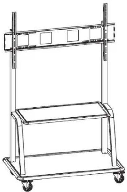
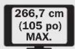
Heavy-Duty Mobile Flat-Panel Floor Stand for TVs and Monitors up to 105"
Model: DMCS60105XXDD
natural_image
Line drawing of a dual-plate industrial cart with wheels and overhead railings (no text or symbols)
CAUTION: DO NOT EXCEED MAXIMUM LISTED WEIGHT
CAPACITY. SERIOUS INJURY OR PROPERTY DAMAGE MAY OCCUR!

200x200/300x200/300x300
400x200/400x300/400x400
600x400/800x400/800x600
900x600/1000x600


Español 9 • Français 17 • Русский 25 • Deutsch 33
WARRANTY REGISTRATION
Register your product today and be automatically entered to win an ISOBAR® surge protector in our monthly drawing! tripplite.com/warranty


1111 W. 35th Street, Chicago, IL 60609 USA • tripplite.com/support
Copyright © 2020 Tripp Lite. All rights reserved.
Important Safety Instructions

WARNING
Read the entire instruction manual before you start assembly and installation. If you have questions about any of the instructions or warnings, contact Tripp Lite Support.
- Do not begin the installation until you have read and understood the instructions and warnings contained in this manual. If you have any questions regarding any of the instructions or warnings, please visit tripplite.com/support.
- This mounting stand was designed to be installed and utilized ONLY as specified in this manual. Improper installation of this product may cause damage or serious injury.
- This product should only be installed by someone of good mechanical ability, with basic building experience and a full understanding of this instruction manual.
- Make sure that the mounting surface can safely support the combined load of the equipment and all attached hardware and components.
• Always use an assistant or mechanical lifting equipment to safely lift and position equipment. - Tighten screws firmly, but do not over-tighten. Over-tightening screws can damage the items, greatly reducing their holding power.
- This product is intended for indoor use only. Using this product outdoors could lead to product failure and personal injury.
Warranty and Product Registration
5-Year Limited Warranty
Seller warrants this product, if used in accordance with all applicable instructions, to be free from original defects in material and workmanship for a period of 5 years from the date of initial purchase. If the product should prove defective in material or workmanship within that period, Seller will repair or replace the product, at its sole discretion.
THIS WARRANTY DOES NOT APPLY TO NORMAL WEAR OR TO DAMAGE RESULTING FROM ACCIDENT, MISUSE, ABUSE OR NEGLECT. SELLER MAKES NO EXPRESS WARRANTIES OTHER THAN THE WARRANTY EXPRESSLY SET FORTH HEREIN. EXCEPT TO THE EXTENT PROHIBITED BY APPLICABLE LAW, ALL IMPLIED WARRANTIES, INCLUDING ALL WARRANTIES OF MERCHANTABILITY OR FITNESS, ARE LIMITED IN DURATION TO THE WARRANTY PERIOD SET FORTH ABOVE; AND THIS WARRANTY EXPRESSLY EXCLUDES ALL INCIDENTAL AND CONSEQUENTIAL DAMAGES. (Some states do not allow limitations on how long an implied warranty lasts, and some states do not allow the exclusion or limitation of incidental or consequential damages, so the above limitations or exclusions may not apply to you. This warranty gives you specific legal rights, and you may have other rights which vary from jurisdiction to jurisdiction.)
WARNING: The individual user should take care to determine prior to use whether this device is suitable, adequate or safe for the use intended. Since individual applications are subject to great variation, the manufacturer makes no representation or warranty as to the suitability or fitness of these devices for any specific application.
PRODUCT REGISTRATION
Visit tripplite.com/warranty today to register your new Tripp Lite product. You'll be automatically entered into a drawing for a chance to win a FREE Tripp Lite product!*
* No purchase necessary. Void where prohibited. Some restrictions apply. See website for details.
Tripp Lite has a policy of continuous improvement. Specifications are subject to change without notice. Photos and illustrations may differ slightly from actual products.
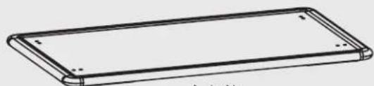
Component Checklist
IMPORTANT: Ensure you have received all parts according to the component checklist prior to installing. If any parts are missing or faulty, visit tripplite.com/support for service.
natural_image
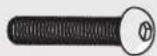
Line drawing of a rectangular electronic device with rounded edges and mounting holes (no text or symbols)A (x1)

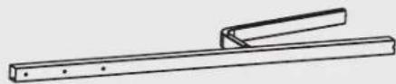
B (x4)

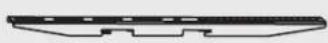
C (x2) D (x2)
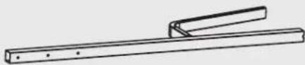
natural_image
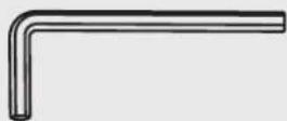
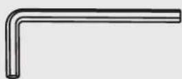
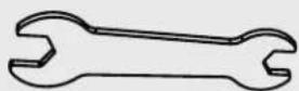
Simple line drawing of a mechanical lever or fulcrum with a handle and shaft (no text or symbols)
natural_image
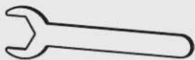
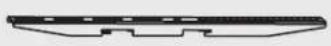
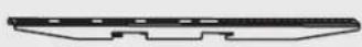
Simple line drawing of a rectangular object with rounded edges (no text or symbols)E (x1)

natural_image
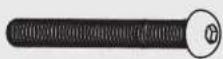
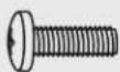
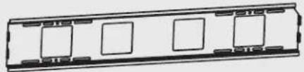
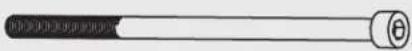
Pure electrical circuit lines without any symbolsF (x1)
G (x2)
Package P

D8-24
H (x4)

D6
L (x4)

D8-16
M (x12)

D6
N (x4)

M8
0 (x4)

M6x 130
K (x4)

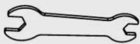
Q (x1) R (x1)5mm P (x1)
M8x 65
J (x4)

M8x 45
I (x8)
Package M
M-A
M5x14 (x4)
M-B
M6x14 (x4)
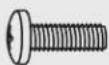
M-C
M6x30 (x4)
M-D
M8x30 (x4)

M-E
M8x50 (x4)

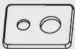
M-F
Washer (x4)

M-G
Smaller Spacer (x8)
M-H
Large Spacer (x8)
1. Assembling the Base
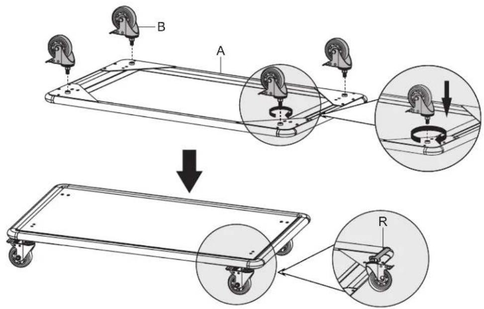

Lock the hexagonal nuts tightly with an included wrench to prevent casters from backing out during use.
2. Assembling the Columns
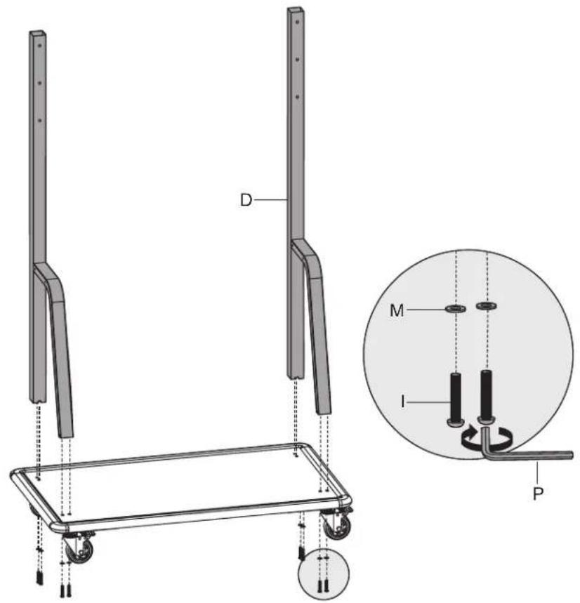
3. Assembling Base to Columns
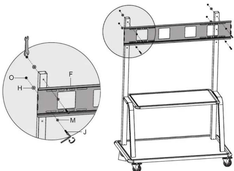
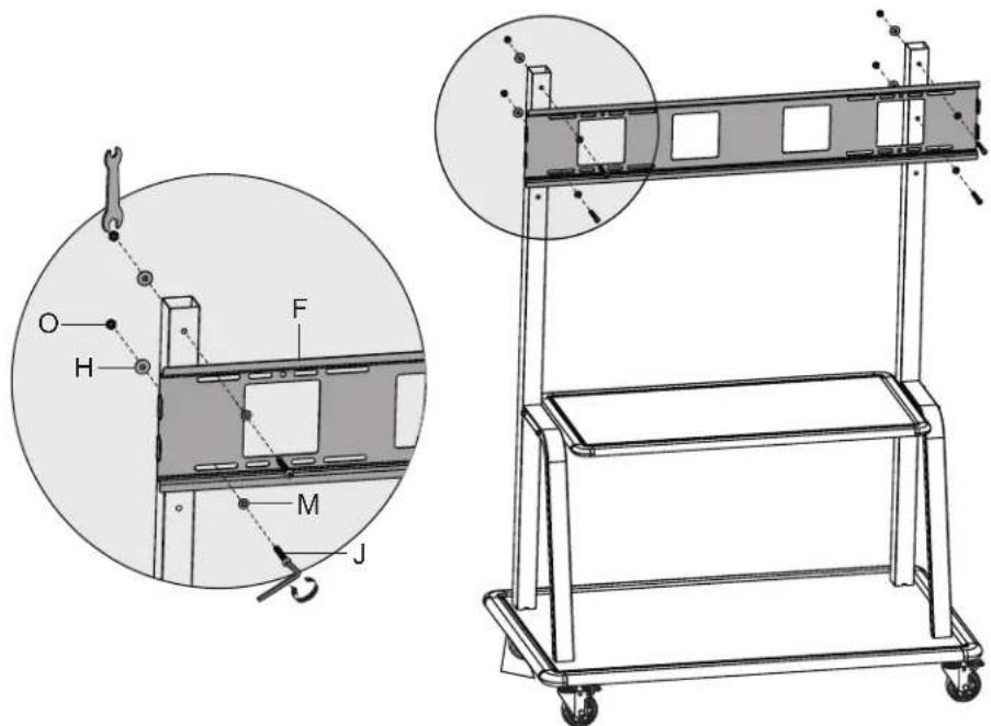
4. Attach Universal Plate to Columns
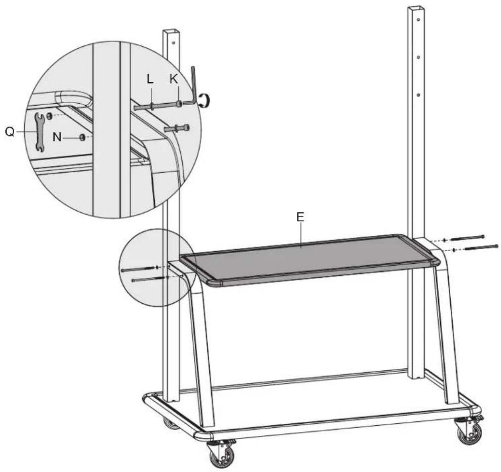
5. Attach Top Covers to Columns
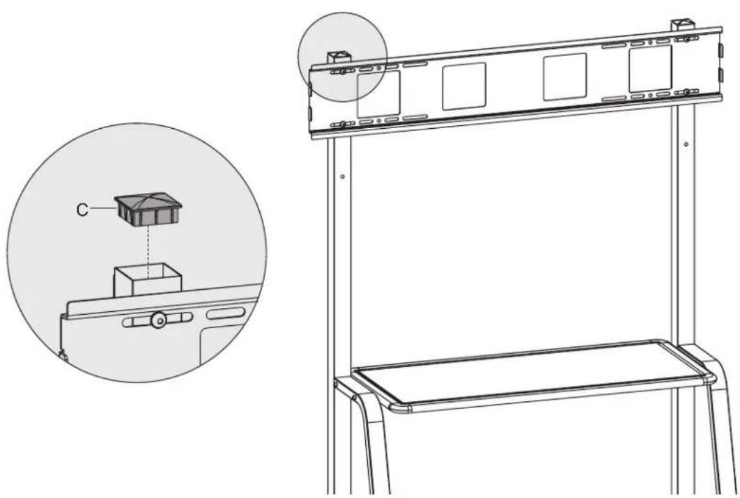
natural_image
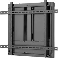
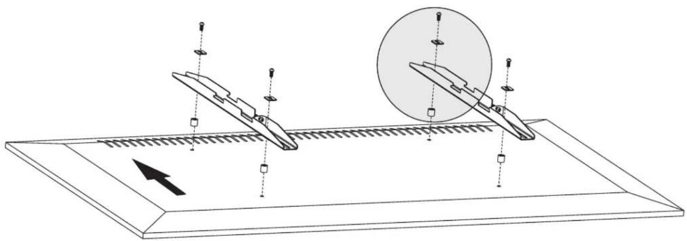
Technical line drawing of a mechanical device with an inset showing a component labeled 'C' (no text or symbols present)6. Attach Adapter Brackets to Display
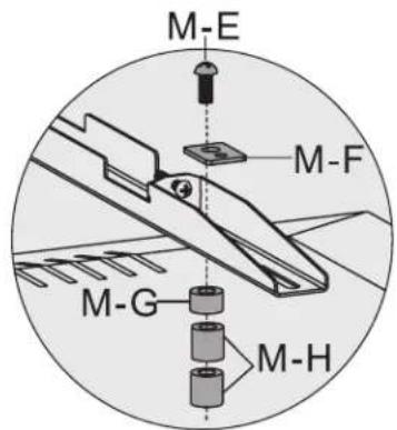
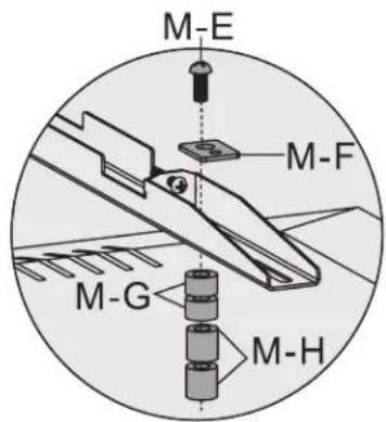
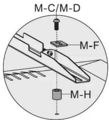
6a. For Flat-Back Screens
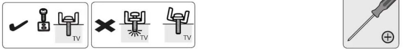

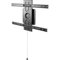
6. Attach Adapter Brackets to Display
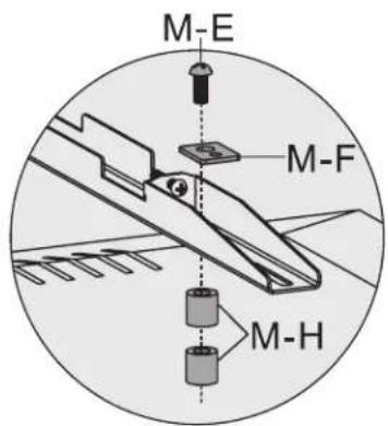
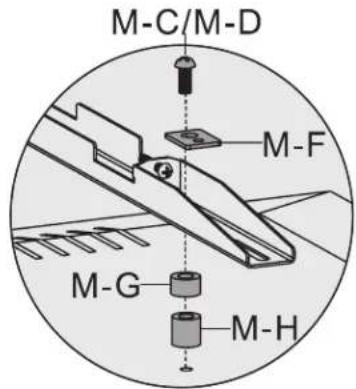
6b. For Recessed Back Screens or Access to A/V Inputs
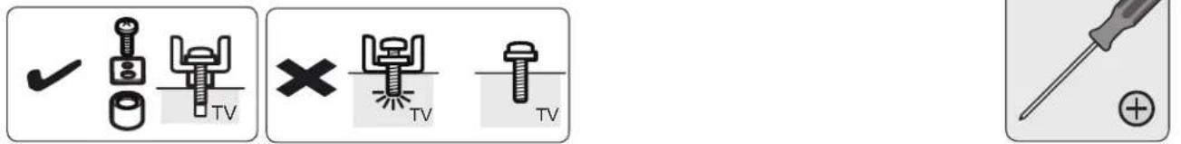

natural_image
Diagram of a mechanical assembly with two blade-like components and a circular component, showing alignment and movement (no text or symbols)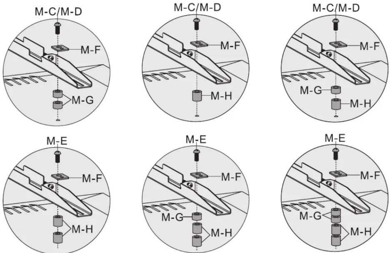
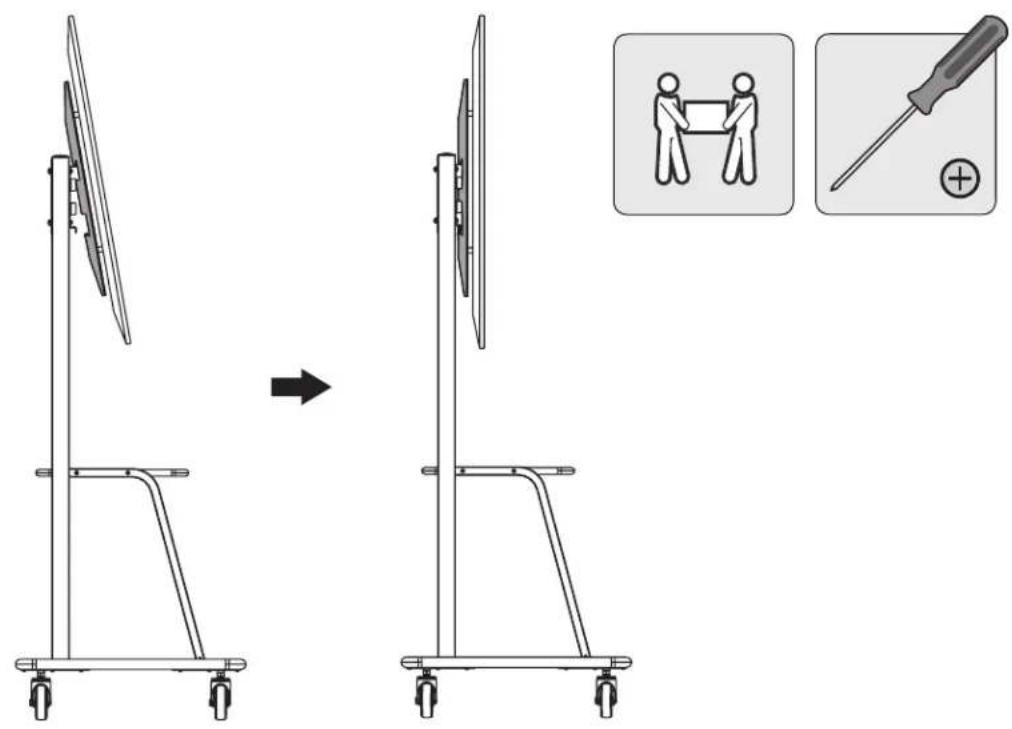
7. Hang the Display Over the Universal Plate

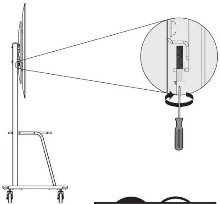
8. Turn the Bottom Screws To Lock
natural_image
Technical line drawing of a mechanical device with a wheel-mounted fan and a screwdriver inserted into a circular component (no text or symbols)
natural_image
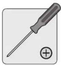
Illustration of a screwdriver with a plus button symbol (no text or labels)MAINTENANCE
- Check that the bracket is secure and safe to use at regular intervals (at least every 3 months)
• For any additional questions, visit tripplite.com/support


Manufacturing Excellence.
1111 W. 35th Street, Chicago, IL 60609 USA • tripplite.com/support
20.08.37D + 93.3DF8_60A
natural_image
Line drawing of a dual-haul industrial cart with wheels and frame structure (no text or symbols)English 1 • Français 17 • Русский 25 • Deutsch 33

200x200/300x200/300x300 400x200/400x300/400x400 600x400/800x400/800x600 900x600/1000x600

![TV TV 150 kg [330 lb] MAXIMO DVD 20 kg 144 lb 20 kg [44 lb] 20 kg 144 lb 20 kg [44 lb] MAXIMO](/content/2026/04/585281/images/d253d8eda54f81a1de9ede640b6ae45798618a26b160f29ab557be69795a12a0.jpg)


1111 W. 35th Street, Chicago, IL 60609, EE UU • tripplite.com/support

natural_image
Technical line drawing of a mechanical device with an inset showing a component labeled 'C' (no text or symbols present)natural_image
Illustration of a screwdriver with a plus button symbol (no text or labels)
natural_image
Diagram of a mechanical assembly with two blade-like components and a circular component, showing alignment and movement (no text or symbols)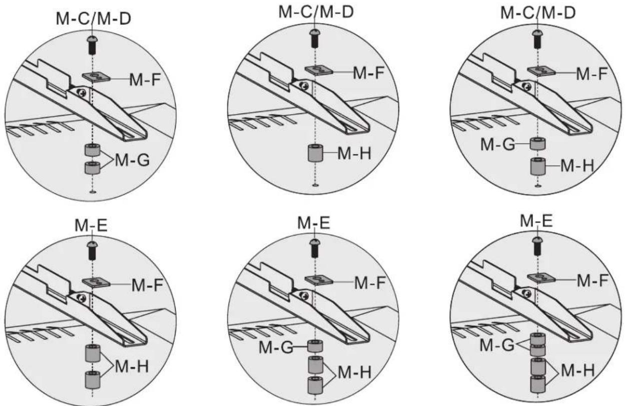
7. Cuelgue la Pantalla Sobre la Placa Universal
natural_image
Illustration of a screwdriver with a plus button symbol (no text or labels)MANTENIMIENTO
1111 W. 35th Street, Chicago, IL 60609, EE UU • tripplite.com/support
20.08.37D • 93.3CRR_R04
natural_image
Line drawing of a dual-plate industrial cart with wheels and vertical supports (no text or symbols)English 1 • Español 9 • Русский 25 • Deutsch 33

MISE EN GARDE : NE PAS EXCÉDER LA CAPACITÉ PONDÉRALE
MAXIMUM INDIQUÉE. CELA RISQUERAIT DE CAUSER
DES BLESSURES GRAVES OU DES DOMMAGES MATÉRIELS!

200x200/300x200/300x300
400x200/400x300/400x400
600x400/800x400/800x600
900x600/1 000x600


1111 W. 35th Street, Chicago, IL 60609 USA tripplite.com/support
natural_image
Simple line drawing of a rectangular electronic device with no text or symbolsA (x1)
B (x4)

C (x2) D (x2)

natural_image
Simple line drawing of a mechanical lever or fulcrum with a handle and shaft (no text or symbols)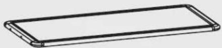
natural_image
Simple line drawing of a rectangular object with rounded edges (no text or symbols)E (x1)
natural_image
Pure electrical circuit lines without any symbolsF (x1)
G (x2)
Emballage P

D8-24
H (x4)

D6
L (x4)

D8-16
M (x12)

D6
N (x4)

M8
O (x4)

M6x 130
K (x4)
Q (x1) R (x1)5 mm P (x1)

M8x 65
J (x4)

M8x 45
1 (x8)
Emballage M

M-A
M5 x 14 (x4)
M-B
M6 x 14 (x4)
M-C
M6x30 (x4)
M-D
M8x30 (x4)
M-E
M8x50 (x4)

M-F
Rondelle (x4)

M-G
Plus petite entretoise (x8)
M-H
Grande entretoise (x8)

4. Fixation de la plaque universelle aux colonnes
natural_image
Technical line drawing of a mechanical device with an inset showing a component labeled 'C' (no text or symbols present)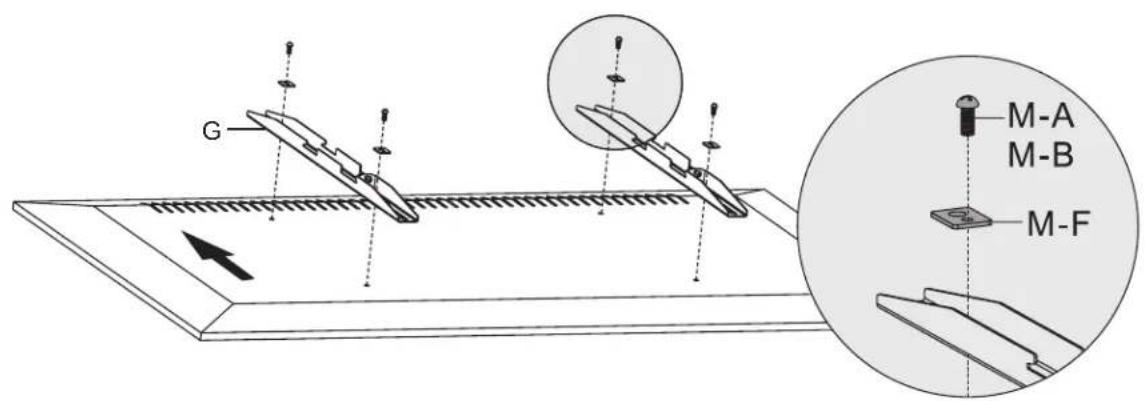

natural_image
Diagram of a mechanical assembly with two tool holders and a circular component, showing alignment and movement (no text or symbols)
natural_image
Technical line drawing of a mechanical device with a wheel-mounted fan and a screwdriver inserted into a circular component (no text or symbols)
natural_image
Illustration of a screwdriver with a plus button symbol (no text or labels)MAINTENANCE
1111 W. 35th Street, Chicago, IL 60609 USA tripplite.com/support
20.08.370 93-3CFS_Rsa
natural_image
Line drawing of a dual-level industrial cart with wheels and structural supports (no text or symbols)English 1 • Español 9 • Français 17 • Deutsch 33

1111 W. 35th Street, Chicago, IL 60609 USA - tripplite.com/support
natural_image
Simple line drawing of a rectangular electronic device with rounded edges and mounting holes (no text or symbols)A (1 шт.)

B(4 шт.)

C (2 шт.) D (2 шт.)
natural_image
Simple line drawing of a mechanical lever or fulcrum with a handle and shaft (no text or symbols)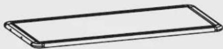
natural_image
Simple line drawing of a rectangular object with rounded edges (no text or symbols)E(1 шт.)

natural_image
Pure electrical circuit lines without any symbolsF(1 шт.)

G(2 шт.)

natural_image
Technical line drawing of a mechanical device with an inset showing a component labeled 'C' (no text or symbols present)natural_image
Illustration of a screwdriver with a plus button symbol (no text or labels)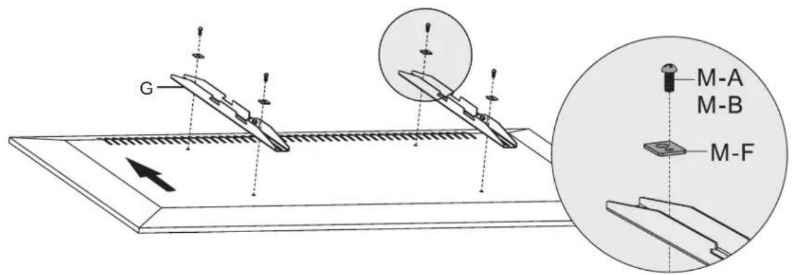

natural_image
Illustration of a screwdriver with a plus button symbol (no text or labels)
natural_image
Diagram of a mechanical assembly with two blade-like components and a circular component, showing alignment and movement (no text or symbols)


natural_image
Technical diagram of a mechanical device with a wheel-mounted fan and a magnified inset showing internal components (no text or symbols)
natural_image
Illustration of a screwdriver with a plus button symbol (no text or labels)
1111 W. 35th Street, Chicago, IL 60609 USA - tripplite.com/support
Benutzerhandbuch
natural_image
Line drawing of a dual-level industrial cart with wheels and overhead railings (no text or symbols)English 1 • Español 9 • Français 17 • Русский 25

200x200/300x200/300x300 400x200/400x300/400x400 600x400/800x400/800x600 900x600/1000x600


1111 W. 35th Street, Chicago, IL 60609 USA • tripplite.com/support
natural_image
Simple line drawing of a rectangular electronic device with no text or symbolsA (x1)

B (x4)

C (x2) D (x2)
natural_image
Simple line drawing of a mechanical lever or fulcrum with a handle and shaft (no text or symbols)
natural_image
Simple line drawing of a rectangular object with rounded edges (no text or symbols)E (x1)
natural_image
Pure electrical circuit lines without any symbolsF (x1)
G (x2)
Paket P

D8-24
H (x4)

D6
L (x4)

D8-16
M (x12)

D6
N (x4)

M8
O (x4)

M6x 130
K (x4)
Q (x1) R (x1)5 mm P (x1)


M8x 65
J (x4)
M8x 45
1 (x8)
Paket M
M-A
M5x14 (x4)

M-B
M6x14 (x4)

M-C
M6x30 (x4)

M-D
M8x30 (x4)

M-E
M8x50 (x4)
M-F
Beilagscheibe (4 x)

natural_image
Technical line drawing of a mechanical device with an inset showing a component labeled 'C' (no text or symbols present)
natural_image
Illustration of a screwdriver with a plus button symbol (no text or labels)
natural_image
Diagram of a mechanical assembly with two tool holders and a circular component, showing alignment and movement (no text or symbols)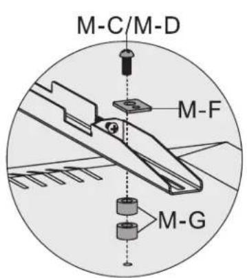


natural_image
Technical line drawing of a mechanical device with a wheel-mounted fan and a screwdriver inserted into a circular component (no text or symbols)
natural_image
Illustration of a screwdriver with a plus button symbol (no text or labels)WARTUNG

Manufacturing Excellence.
1111 W. 35th Street, Chicago, IL 60609 USA • tripplite.com/support
20.08.37D + 93.3DF8_60VA