Chef Collection FG21MA1EABG - Oven Furrion - Free user manual and instructions
Find the device manual for free Chef Collection FG21MA1EABG Furrion in PDF.
| Product Type | Gas oven for recreational vehicle |
| Brand | Furrion |
| Model | Furrion Chef Collection FG21MA1EABG (also FG21MA1EA-SS, FG21MA1EA-BG, FS22N20A-SS) |
| Dimensions (W x H x D) | 628 x 656 x 562 mm (24 1/4 x 25 1/8 x 22 1/8 in) |
| Interior Volume | 58 L |
| Power Supply | 12 V DC, < 2 A (15 A fuse recommended) |
| Fuel | Propane (LPG) |
| Heating Power | 9,000 BTU/h |
| Gas Inlet Pressure | 11 to 13.8 WC (2737 to 3434 Pa) |
| Ignition Type | Electronic ignition with pilot light |
| Functions | Baking, digital timer (up to 23:59), interior light, LED display |
| Oven Rack | 1 adjustable rack with anti-tilt lock |
| Included Accessories | Rack, drip tray, baking sheet |
| Oven Light | Halogen bulb G4, 12 V, 20 W, resistant to 572 °F (300 °C) |
| Materials | Stainless steel, enamel |
| Maintenance | Regular cleaning with soapy water; do not use abrasive products or steam cleaner |
| Safety | Safety shut-off (pilot light), rack lock, door gasket, mandatory ventilation |
| Installation | Built-in into a cabinet, min. clearance 2 in (51 mm) side, 30 in above with cooktop |
| Weight | Not specified (estimated ~30 kg) |
Frequently Asked Questions - Chef Collection FG21MA1EABG Furrion
User questions about Chef Collection FG21MA1EABG Furrion
0 question about this device. Answer the ones you know or ask your own.
Ask a new question about this device
Download the instructions for your Oven in PDF format for free! Find your manual Chef Collection FG21MA1EABG - Furrion and take your electronic device back in hand. On this page are published all the documents necessary for the use of your device. Chef Collection FG21MA1EABG by Furrion.
USER MANUAL Chef Collection FG21MA1EABG Furrion
natural_image
Line drawing of a standard oven with two control knobs and a door (no text or symbols)Thank you for purchasing this Furrion® product. Before operating your new appliance, please read these instructions carefully. This instruction manual contains information for safe use, installation and maintenance of the appliance.
Please keep this instruction manual in a safe place for future reference. This will ensure safe use and reduce the risk of injury. Be sure to pass on this manual to new owners of this appliance.
The manufacturer does not accept responsibility for any damages due to not observing these instructions.
WARNING: If the information in this manual is not followed exactly, a fire or explosion may result causing property damage, personal injury or death.
- Do not store or use gasoline or other flammable vapors and liquids in the vicinity of this or any appliance.
—WHAT TO DO IF YOU SMELL GAS:
- Do not try to light any appliances.
- Do not touch any electrical switches.
- Do not use any phone in your recreational vehicle.
- Clear the recreational vehicle of all occupants.
- Turn off the LP container valve or main container.
- Immediately call your gas supplier for instructions.
- If you cannot reach your gas supplier, call the fire department.
- Have the gas system checked and leakage source corrected by a qualified installer, service agency, manufacturer, dealer or the gas supplier.
Table of Contents
Table of Contents....1
Explanation of Symbols 2
Important Safety Instructions....2
General Safety Warnings 2
Oven Safety Warnings....3
Product Overview 4
Installation 4
What's in the Box 4
Cabinet Cutout Instructions....4
Oven Installation....5
Ventilation Installation....5
Cooktop Installation 6
Electrical Connection 6
Gas Connection 6
Operation....7
Leak Check....7
Lighting Instructions 7
Shut off Instructions 7
The Burner Flame 7
Cooking Advice 8
Cooking Pizza....8
Cooking Fish and Meat 8
Cleaning and Maintenance 8
How to Keep Your Oven in Shape....8
Oven Rack Guide 8
Removing the Oven Door 9
Replacing the Oven Light 10
Replacing the Control Knob LED 10
Storage 11
Troubleshooting....11
Specifications....12
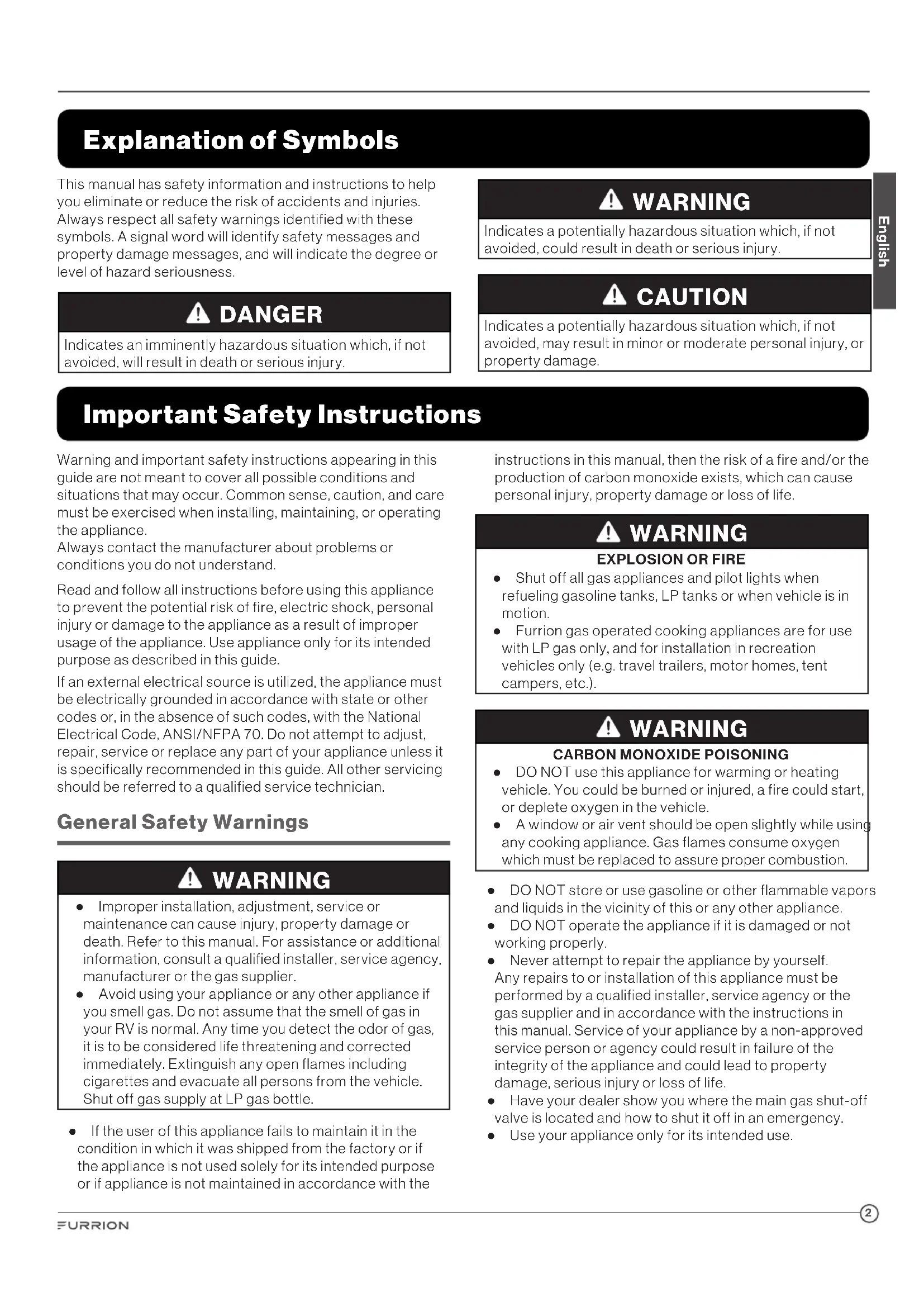
Explanation of Symbols
This manual has safety information and instructions to help you eliminate or reduce the risk of accidents and injuries. Always respect all safety warnings identified with these symbols. A signal word will identify safety messages and property damage messages, and will indicate the degree or level of hazard seriousness.

DANGER
Indicates an imminently hazardous situation which, if not avoided, will result in death or serious injury.

WARNING
Indicates a potentially hazardous situation which, if not avoided, could result in death or serious injury.

CAUTION
Indicates a potentially hazardous situation which, if not avoided, may result in minor or moderate personal injury, or property damage.
Important Safety Instructions
Warning and important safety instructions appearing in this guide are not meant to cover all possible conditions and situations that may occur. Common sense, caution, and care must be exercised when installing, maintaining, or operating the appliance.
Always contact the manufacturer about problems or conditions you do not understand.
Read and follow all instructions before using this appliance to prevent the potential risk of fire, electric shock, personal injury or damage to the appliance as a result of improper usage of the appliance. Use appliance only for its intended purpose as described in this guide.
If an external electrical source is utilized, the appliance must be electrically grounded in accordance with state or other codes or, in the absence of such codes, with the National Electrical Code, ANSI/NFPA 70. Do not attempt to adjust, repair, service or replace any part of your appliance unless it is specifically recommended in this guide. All other servicing should be referred to a qualified service technician.
General Safety Warnings

WARNING
- Improper installation, adjustment, service or maintenance can cause injury, property damage or death. Refer to this manual. For assistance or additional information, consult a qualified installer, service agency, manufacturer or the gas supplier.
- Avoid using your appliance or any other appliance if you smell gas. Do not assume that the smell of gas in your RV is normal. Any time you detect the odor of gas, it is to be considered life threatening and corrected immediately. Extinguish any open flames including cigarettes and evacuate all persons from the vehicle. Shut off gas supply at LP gas bottle.
- If the user of this appliance fails to maintain it in the condition in which it was shipped from the factory or if the appliance is not used solely for its intended purpose or if appliance is not maintained in accordance with the
instructions in this manual, then the risk of a fire and/or the production of carbon monoxide exists, which can cause personal injury, property damage or loss of life.

WARNING
EXPLOSION OR FIRE
- Shut off all gas appliances and pilot lights when refueling gasoline tanks, LP tanks or when vehicle is in motion.
- Furrion gas operated cooking appliances are for use with LP gas only, and for installation in recreation vehicles only (e.g. travel trailers, motor homes, tent campers, etc.).

WARNING
CARBON MONOXIDE POISONING
- DO NOT use this appliance for warming or heating vehicle. You could be burned or injured, a fire could start, or deplete oxygen in the vehicle.
-
A window or air vent should be open slightly while using any cooking appliance. Gas flames consume oxygen which must be replaced to assure proper combustion.
-
DO NOT store or use gasoline or other flammable vapors and liquids in the vicinity of this or any other appliance.
- DO NOT operate the appliance if it is damaged or not working properly.
- Never attempt to repair the appliance by yourself. Any repairs to or installation of this appliance must be performed by a qualified installer, service agency or the gas supplier and in accordance with the instructions in this manual. Service of your appliance by a non-approved service person or agency could result in failure of the integrity of the appliance and could lead to property damage, serious injury or loss of life.
- Have your dealer show you where the main gas shut-off valve is located and how to shut it off in an emergency.
-
Use your appliance only for its intended use.
-
Children should be taught that the appliance is not a toy. They should not be allowed to play with the controls or any other parts of the appliance. Do not allow anyone to stand or sit on top of the appliance. Not only can this damage the appliance, but personal injuries could result.
- Do not store items of interest to children in cabinets above or near the appliance. Children climbing on the appliance to reach items could be seriously injured.
- All control knobs must be turned off when not in use. Fire and/or burning hazard may occur if a burner is accidentally left on.
- If any burner should extinguish (after initially lighting or due to accidental blow-out), turn all burner knobs off and wait five (5) minutes before attempting to relight the burner.
- DO NOT store flammable materials on, in, or near the appliance. Any fumes can create an explosion and/or fire hazard.
- Do not wear loose fitting clothing or long-hanging sleeved clothing while using the appliance. If they contact the open flame of the burner, they could ignite and cause severe burns.
- Use only dry potholders to remove hot utensils. Using damp potholders on hot surfaces could result in burns to hands. Do not use a towel or bulky cloth for a pot holder. The cloth could contact open flame and catch fire.
- Never heat an unopened container. Pressure build-up within the container can cause it to explode.
- Do not use water on grease fires. Never pick-up a flaming pan. Smother a flaming pan with a lid or flat pan. Flaming grease outside the pan can be extinguished with baking soda or a multipurpose dry chemical fire extinguisher.
- This appliance is intended to be built-in to a cabinet structure only and is not intended for attachment to the building structure.
Oven Safety Warnings
- DO NOT TOUCH HEATING ELEMENTS OR INTERIOR SURFACES OF OVEN – Heating elements may be hot even though they are dark in color. Interior surfaces of an oven become hot enough to cause burns. During and after use, do not touch, or let clothing or other flammable materials contact heating elements or interior surfaces of oven until they have had sufficient time to cool. Other surfaces of the appliance may become hot enough to cause burns – among these surfaces are (identification of surfaces – for example, oven vent openings and surfaces near these openings, oven doors, and windows of oven doors).
- DO NOT touch the outer surface of the oven door or the oven vent while the oven is in use. These areas may become hot enough to cause burns. During and after use, do not let clothing or other flammable materials contact these areas until they have had sufficient time to cool.
- DO NOT cover the ventilation holes in the Flame Spreader Rack (shelf above oven burner). The air circulation inside the oven will be interrupted and cooking times will vary from normal, food may be burned or undercooked.
• DO NOT use oven as a storage area. - If oven pilot should extinguish after initial lighting or due to accidental blowout, turn oven knob off and wait five (5) minutes before again attempting to relight the oven.
- Always place oven racks in desired location while oven is cool. If rack must be moved while oven is hot, do not let potholder contact hot heating element in oven.
- Use care when opening the oven door, let hot air or steam escape before removing or replacing food.
- Do not cover the oven vent openings whenever oven is being used. Covering the vents restricts the flow of combustion air to the oven burner and could cause poor combustion and the formation of carbon monoxide.
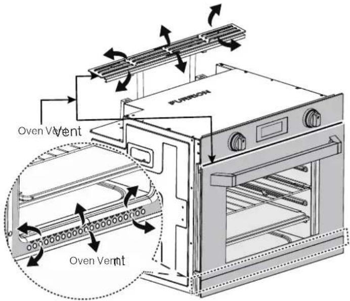
text_image
PVBRON Oven Vent Oven VentProduct Overview
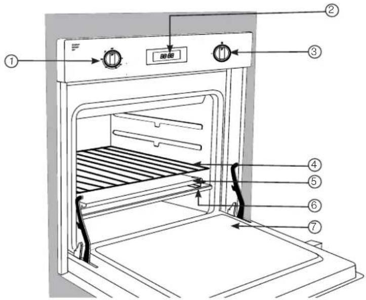
text_image
① ② ③ ④ ⑤ ⑥ ⑦| Item Description | |
| 1 | Oven Control Knob |
| 2 | LED Display |
| 3 | Timer Control. Sets timer for up to 23 hours 59 minutes. |
| 4 | Adjustable Oven Rack |
| 5 | Drip Tray |
| 6 | Baking Tray |
| 7 | Oven Door |
Installation

WARNING
FIRE, EXPLOSION, BURN INJURY CARBON MONOXIDE POISONING
- The cooking appliance must be completely separated and/or sealed from other air moving or air consuming devices such as, but not limited to furnaces, microwave ovens clothes dryers, cooling fans and doors or drawers in common cabinets. Failure to do so will affect the appliance(s) combustion air supply by creating either a negative or positive draft.
- NEGATIVE DRAFT caused by air moving appliances may draw the top burner flame down into or toward the cooktop resulting in cooktop damage, burn hazard, explosion possibility and/or carbon monoxide build up.
- POSITIVE DRAFT may blow out the top burner flame during use resulting in an explosion and/or fire hazard and/or injury to the occupants of the vehicle.
- DO NOT operate the appliance in excessive windy conditions as this may cause a negative or positive draft.

WARNING
Installation of this appliance must be made in accordance with the written instructions provided in this manual. No agent, representative or employee of Furrion or other persons has the authority to change, modify or waive any provision of the instructions contained in this manual.
NOTE: Ensure the countertop, surrounding materials and bonding agents have a temperature rating of no less than 203^ F ( 95^ C).
The installation must conform with local codes or in the absence of such codes, refer to the latest edition of: In the U.S.A.:
a. Standard for Recreational Vehicles NFPA 1192.
b. National Fuel Gas Code ANSI Z223.1/NFPA 54.
In Canada, the installation must conform with:
a. Standard CAN/CSA Z-240.4.2-08, Installation Requirements for Propane Appliances and Equipment in Recreational Vehicles.
b. Any applicable local codes and regulations.
What's in the Box
Make sure you have all the following items included in the packaging. If any item is damaged or missing, contact your dealer.
Gas Oven x 1
- Rack x 1
- Drip Tray x1
- Baking Tray x 1
• Instruction Manual x 1
• Warranty Leaflet x 1
Cabinet Cutout Instructions
For proper operation of your cooking appliance, the cabinets must be properly constructed and squared with respect to the counter top and the cabinet face.
For proper operation of these units, the oven must be level.
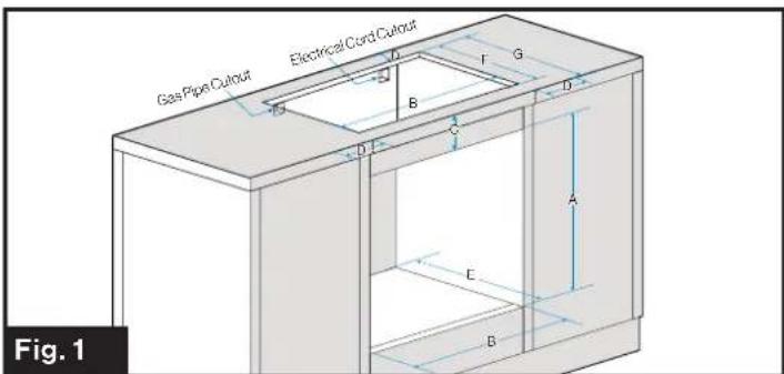
NOTE: When the appliance is used together with a Furrion gas cooktop or induction cooktop, the cabinet cutout must be located with respect to the minimum clearance to combustible materials (minimum clearances from combustible materials: 2 inches from the rear, left and right sides (see D dimension in Fig. 1) and 30 inches from the top if a cooktop is installed). When planning the location, consider curtains or other combustible materials to be installed around the oven.
Gas Oven with Gas or Electric Cooktop (Fig. 1)
text_image
Gas Pipe Cutout Electrical Cord Cutout D F G B D C A E B Fig. 1| ABCDEFG | ||||||
| 20 12 "525mm | 23 12 "597mm | 4"101mm | Min. 2"51mm | Min. 16 18 "522mm | 16 34 "426mm | Min. 18 38 "467mm |
The recommended minimum distance between the floor and the bottom of the cutout opening is 4" (101mm).
Oven Installation
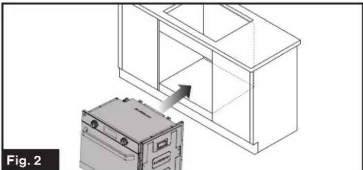
When the cabinet has been prepared according to the dimensions given above and the gas line is in place.
- Remove the oven from its packaging and slide the oven into the cabinet opening. (Fig. 2)
natural_image
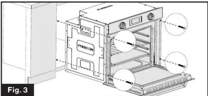
Line drawing of a cabinet with an air conditioner unit inserted, showing airflow direction (no text or symbols)- Verify the oven is level from side to side and front to rear.
- Open the oven door and securely fasten the oven in place with four screws (not provided). (Fig. 3)
text_image
PUBRECH Fig. 3Ventilation Installation
After securely mounting the oven into the cabinet, install the vent through the top cutout area of the cabinet.
- Install the vent outer flue assembly onto the top of the oven unit. Ensure the outer flue slides over the middle flue opening on the oven. Ensure the vent outer flue vent assembly has the cooktop edge support facing forward. (Fig 4)
WARNING
The minimum overlap of the vent outer flue and the vent oven middle flue is 34 ". Refer to Fig. 4 for assembly instructions.
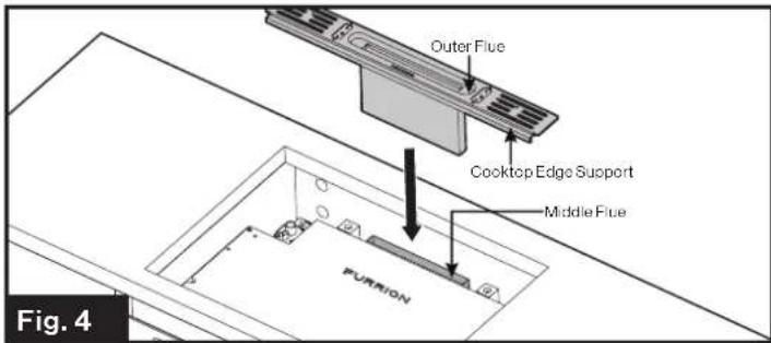
text_image
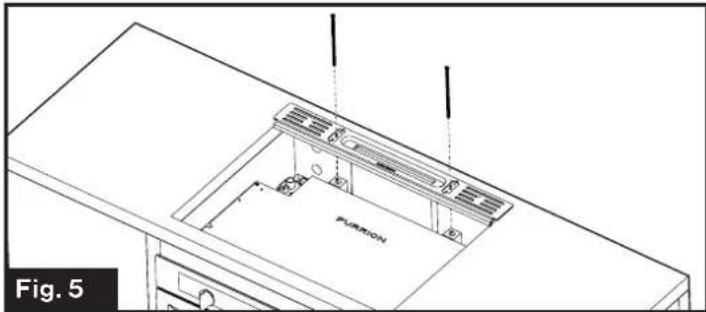
Outer Flue Cooktop Edge Support Middle Flue PURION Fig. 4- Fix the vent assembly to the oven with the two screws provided (M4x140mm) and tighten with screwdriver. Do not over tighten. (Fig. 5)
natural_image
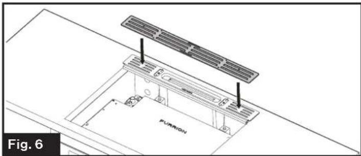
Isometric line drawing of a kitchen appliance with ventilation duct and labeled component 'PUMRON', no text or symbols present- Place the vent cover over the vent assembly. Make sure the vent cover louvers are facing forward. (Fig. 6 & Fig. 7) NOTE: The Vent is pokey yoked with the vent trim attachment screw holes to have the louvers facing forward.
natural_image
Technical line drawing of a solar panel installation with labeled components (no text or symbols beyond label)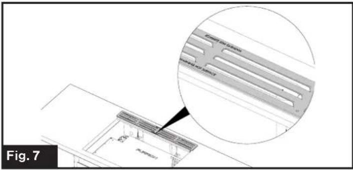
text_image
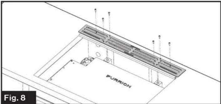
Fig. 7- Secure the vent cover onto the vent assembly with the six screws provided (M3 x 8mm). (Fig. 8)
natural_image
Technical line drawing of a structural support frame with ventilation grilles and labeled 'FURION' (no other text or symbols)Cooktop Installation
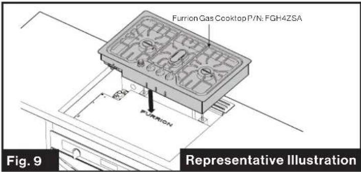
This oven is designed and can be used with a Furrion gas or electric cooktop, please refer to corresponding cooktop instruction manual on how to construct the cabinet and install the cooktop over the oven. (Fig. 9 & Fig 10)
text_image
Furrion Gas Cooktop P/N: FGH4ZSA FURION Fig. 9 Representative Illustration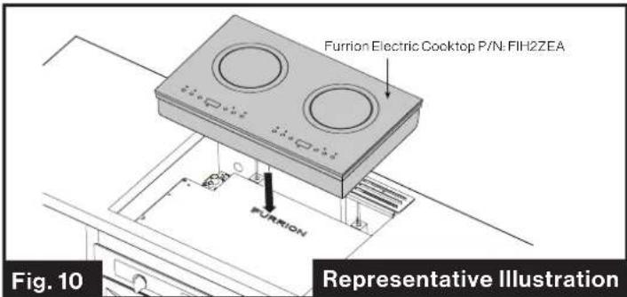
text_image
Furrion Electric Cooktop P/N FIH2ZEA FURION Fig. 10 Representative IllustrationElectrical Connection
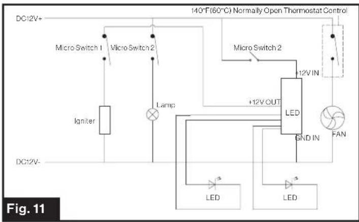
- The power supply of this oven is 12V. Connect the components below separately. (Fig. 11)
NOTE: Ensure to connect the wires with the correct polarity. Black is "+" and White is "−".
- 12V power for: Igniter, Oven Light, Cooling fan, Electronic Timer & Display, 140°F (60°C) Thermostat Control.
- Feed the cable through the electrical cord cutout on the upper rear-right corner of the cabinet, use a 15A fuse at the power source for protection.
- The nameplate is located on top of the oven, refer to the label for the technical specifications.
text_image
DC12V+ Micro Switch 1 Micro Switch 2 Igmiter Lamp DC12V- 140°F(60°C) Normally Open Thermostat Control Micro Switch 2 +12V IN LED GND IN FAN LED LED Fig. 11Gas Connection
WARNING
Gas supply pipe must be installed with clearance from knives contacting or cutting gas lines.
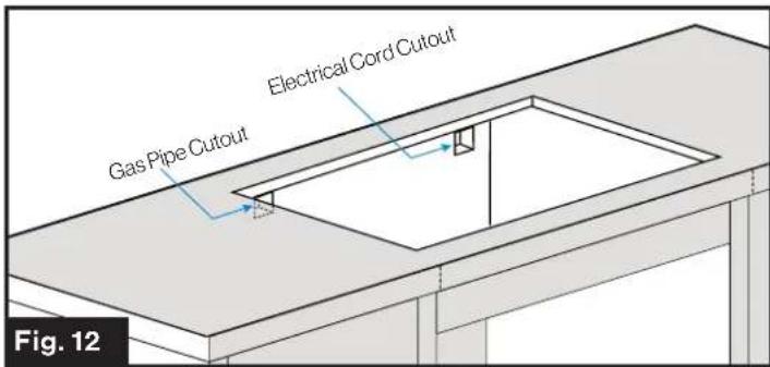
Connect a propane supply line with a 38 " Flare Female connection to the gas oven in the upper left rear corner of the cabinet. (Fig. 12) Tighten the gas line joint to the gas oven using 2 wrenches.
IMPORTANT: Leave adequate space around the gas supply pipe in case of bend or damage during installation. Make sure the gas supply pipe cannot contact any moving parts after installed. Be sure all openings in the cabinet around the gas line are sealed at time of installation.
text_image
Gas Pipe Cutout Electrical Cord Cutout Fig. 12Check that the Connection Is Tight
When installation is completed, check the pipe fittings for leaks using a gas leak detection solution. Never use a flame.
Leak Check

WARNING
FIRE OR EXPLOSION
- Extinguish all open flames.
- NEVER leak test when smoking. Never use a flame.
- Do not use the appliance until connection has been leak tested and does not leak.
• Pressure/Leak test using 11-13.8 WC pressure.

WARNING
- Gas leaks may occur in your system and result in a dangerous situation. Always perform a leak test for possible leaks according to the manufacturer's instructions after installation and before any operation.
- Gas leaks may not be detected by smell alone. Gas suppliers recommend you purchase and install a UL approved gas detector.
WARNING
- DO NOT use matches, candles or other sources of ignition when checking for gas leaks.
- Do not smoke while leak testing.
- Never leak test with an open flame.
Please follow below steps to make leak test for the appliance:
- Extinguish all open flames.
- Turn the gas supply valve and control knobs off.
- Prepare soap solution mixing of equal parts mild detergent or liquid soap and water.
- Spray the soap solution on all gas connections and gas pipes of the appliance.
- Turn the gas supply valve on and inspect all gas connections for bubbles:
- If no bubbles appeared, there is no gas leak in the appliance
- If bubbles appeared, where there are bubbles, where there is a leak point.
- If a gas leak is detected, tighten the connection and repeat the above steps. If the leak is on the gas supply line connection, replace the gas supply line and repeat above steps.
NOTE: It is also recommended that you perform a leak test at least once a year whether the propane gas supply cylinder has been disconnected or not.
Operation

WARNING
Keep your arms and face away from being directly above the cooking area while in operating the appliance.
Lighting Instructions
- Before lighting, reset gas control knobs to the OFF position.
- Check that the main inlet gas valve is OPEN.
- Keep the oven door in the open position for the full ignition process to view the pilot and burner until lit.
- Push and turn the gas control knob counterclockwise to ♦ position until pilot lights. (You will hear a clicking sound when the knob is pushed in.)
- If ignition does not occur in 5 seconds, turn gas control knob off, wait 5 minutes and repeat the lighting procedure.
- Once the pilot flame is lit, continue to hold the oven control knob in for 10-15 seconds, then release knob and verify pilot stays lit. Repeat the above steps if pilot goes out after releasing the knob. (Keep the oven door open for this process)
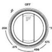
- After the pilot flame is ignited and the control knob is released, then turn the control knob counter-clockwise to the required temperature setting.
- Verify visually that the oven burner has ignited once the control knob has been set to the desired temperate. The burner flame should ignite within a few seconds.
- After verifying the burner has ignited, please close the oven door to continue the preheat process.
Shut off Instructions
- To extinguish the burner, push the oven control knob and rotate clockwise to OFF position. Extinguish all pilot flames when refueling or traveling.
- Turn the main gas supply off.
- Before transit, turn the main gas supply off at the shut off valve.
- The fan may continue to run for 10 - 15 minutes after turning the oven off.
The Burner Flame
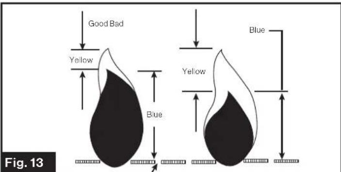
Flames should appear similar to the good flame shown in diagram below. (Fig. 13)
text_image
Good Bad Yellow Blue Blue Yellow Fig. 13A good flame should be blue with a yellow tip. Some yellow tips on flames up to 1 inch in length are acceptable as long as no carbon or soot deposits appear.
If flames are excessively yellow and irregular, the oil residue may not be completely burned off, or the venturi may be clogged or may not be properly positioned over the orifices.
Cooking Advice
The oven offers a wide range of alternatives which allow you to cook any type of food in the best possible way. With time you will learn to make the best use of this versatile cooking appliance and the following directions are only a guideline which may be varied according to your own personal experience.
WARNING
Food Poisoning Hazard
Do not let food sit in oven more than one hour before or after cooking. Doing so can result in food poisoning sickness.
Cooking Pizza
For tasty crispy pizzas:
- Slide the baking tray into the oven.
• Preheat the oven for at least 20 minutes. - Use a light colored pizza pan, placing it on the rack supplied with the oven. If the dripping pan is used, this will
extend the cooking time, making it difficult to get a crispy crust.
- Do not open the oven door frequently while the pizza is cooking.
Cooking Fish and Meat
When cooking white meat, fowl and fish, use temperature settings from 350^ F ( 176^ C) to 425^ F ( 218^ C).
For red meat that should be well done on the outside while tender and juicy in the inside, it is a good idea to start with a high temperature setting "400°F (205°C)\~425°F (218°C)" for a short time, then turn the oven down afterwards.
In general, the larger the roast, the lower the temperature setting. Place the meat on the center of the rack and place the dripping pan beneath to catch the fat.
Make sure that the drip tray is placed in the center of the oven. If you would like to increase the amount of heat from below, use the low rack heights. For savory roasts (especially duck and wild game), dress the meat with lard or bacon on the top.
Cleaning and Maintenance
How to Keep Your Oven in Shape
Before cleaning your oven, or performing maintenance, disconnect it from the power supply.
To extend the life of your oven, it must be cleaned frequently. Keep in mind that:
- Do not use steam equipment to clean the appliance.
- The enameled or stainless steel parts should be washed with lukewarm water without using any abrasive powders or corrosive substances which could ruin them; Stainless steel could get stained. If these stains are difficult to remove, use special products available on the market. After cleaning, it is advisable to rinse thoroughly and dry.
- The inside of the oven should preferably be cleaned after use, when it is still warm, when it is still warm, with hot water and soap; the soap should be rinsed away and the interior should be dried throughly. Avoid using abrasive detergents (for example cleaning powders, etc...) and abrasive sponges for dishes or acids (such as limescale-remover, etc...) as these could damage the enamel. If the grease spots and dirt are particularly tough to remove, use a special product for oven cleaning by following the instructions provided on the packet.
- If you use your oven for an extended period of time, condensation may form. Dry it using a soft cloth.
- There is a rubber seal surrounding the oven opening which guarantees its perfect functioning. Check the condition of this seal on a regular basis. If necessary, clean it and avoid using abrasive products or objects to
do so. Should it become damaged, please contract your nearest After-sales Service Center. We recommend you avoid using the oven until it has been repaired.
- Never line the oven bottom with aluminium foil, as the consequent accumulation of heat could compromise the cooking and even damage the enamel.
- Clean the glass door using non-abrasive products or sponges and dry it with a soft cloth.
Oven Rack Guide
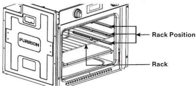
The oven rack feature an anti-tip locking system.
- To remove the rack push inside fully, then unclip the rear tabs from the locking channel by pushing upwards and slide forward.
- To insert the oven rack, position the oven rack just above the rack position desired. The rack should slide easily towards the back and will drop down once fully pushed in. To lock the rack into position, pull the rack forward slightly and then push the rack in to lock down the front section of the rack. (See the rack position as below.)
text_image
PURRON Rack Position RackRemoving the Oven Door

WARNING
When removing the door:
- Do not place excessive weight on an open oven door or stand on an open oven door as, in some cases, it could cause the range to tip over, break or damage the door to the extent that the range would be unsafe to use, or cause serious injury to the user.
- When opening the oven door, allow steam and hot air to escape before reaching in oven to check, add or remove food.
- Make sure oven is cooled down and powered off before removing the door. Failure to do so could result in electrical shock or burns.
- The oven door is heavy and fragile. Use both hands to remove the oven door. The door front is glass. Handle carefully to avoid breaking.
- Grasp only the left and right sides of the oven door. Do not grasp the handle as it may swing in your hand and cause damage or injury.
- Failure to grasp the oven door firmly and properly could result in personal injury or product damage.
-
To avoid injury from the hinge bracket snapping closed, be sure that both levers are securely in place before removing door (Fig. 15a). Also, do not force door open or closed - the hinge could be damaged and injury could result.
-
Be sure to read the above WARNING before attempting to remove oven door.
- Open the door to its fully open position. (Fig. 14)
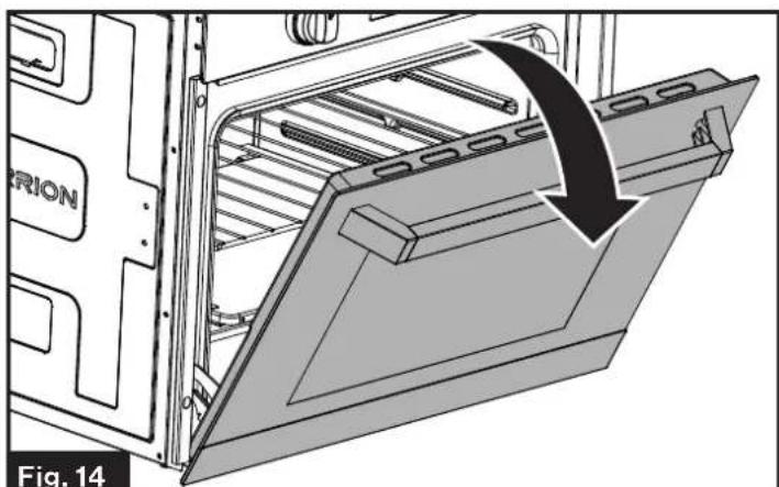
natural_image
Technical illustration of an oven with a door mechanism and a curved arrow indicating motion (no text or symbols)- Rotate the Hinge (one on each side) toward you to buckle the lever. (Fig. 15)

text_image
a Hinge Lever b Fig. 15- Close the door until it stops. (Fig. 16)
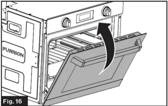
natural_image
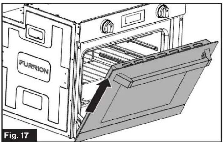
Diagram of an oven with a furrion and labeled components, showing internal structure and airflow direction (no text or symbols beyond labels)- Holding the door firmly on the left and right sides using both hands, pull the door straight out of the hinge slots. (Fig. 17 and Fig. 18)

WARNING
Hold firmly, the door is heavy.
text_image
FURRION Fig. 17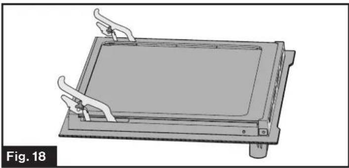
natural_image
3D mechanical assembly diagram showing a rectangular frame with clamps and a central plate, labeled Fig. 18 (no text or symbols on the diagram itself)- Place the door on a protected flat place so that the glass door will not be damaged.
- Follow the steps below to re-attach to the oven door (Fig. 19):
- Insert the hinge into the top slot as shown in Fig 19 ^a .
- Open the door to its fully open position as shown in Fig 19 ^b . Ensure the hinge buckle has released from the lever as shown in Fig 19 ^c .
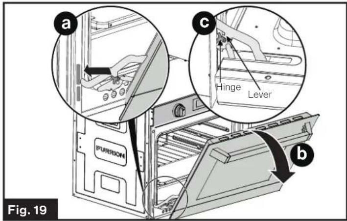
text_image
a b c Hinge Lever PURUON Fig. 19Replacing the Oven Light
- Disconnect the oven from the power supply by the electrical mains or fuse.
- Ensure the oven has cooled before servicing the oven light.
- Remove the glass cover of the lamp-holder. (Fig. 20)
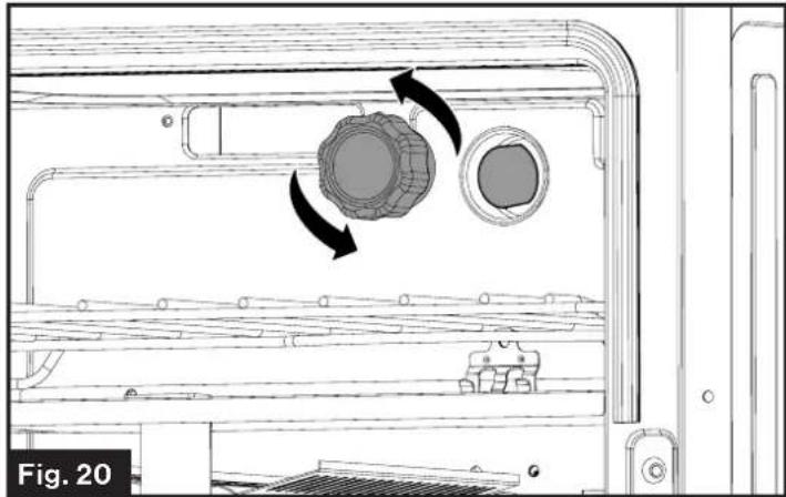
natural_image
Technical diagram of a mechanical device showing internal components and directional arrows (no text or symbols)- Remove the lamp and replace with a lamp resistant to high temperatures (572°F) with the following characteristics:
- Voltage: 12V
- Wattage: 20W
- Type: G4
-
Lamp Type: Halogen
-
Replace the glass cover.
-
Reconnect the power to the oven.
To reorder the Furrion oven light bulb replacement, please call Furrion service for assistance.
Replacing the Control Knob LED
- Disconnect the oven from the power supply by means of the switch used to connect the appliance to the electrical mains or fuse.
Grasp and pull out the control knob with the broken LED light. (Fig. 21)
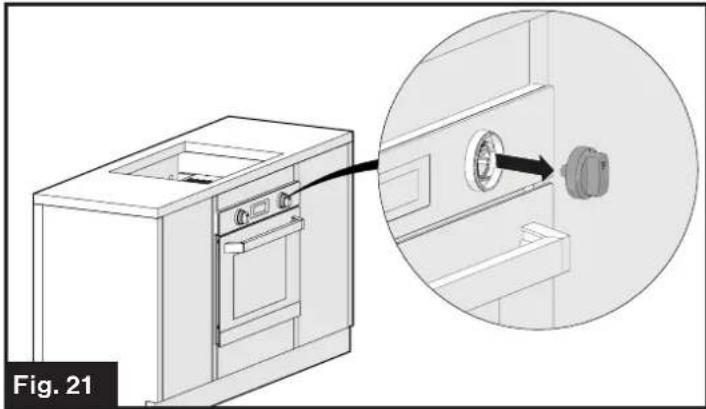
natural_image
Technical illustration of a washing machine with an inset close-up showing the internal components (no text or symbols)- Remove the two screws holding the LED light using a Phillips screwdriver. (Fig. 22)
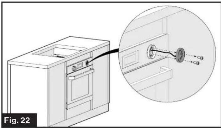
natural_image
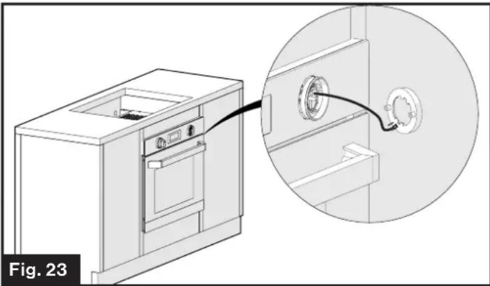
Technical illustration of a kitchen appliance with an inset close-up showing internal components (no text or symbols)- Remove the LED assembly and disconnect the wire from the base of the LED assembly. (Fig. 23)
natural_image
Technical line drawing of a kitchen appliance with an inset close-up showing a circular component inserted into a wall (no text or symbols)- Plug the wire harness connector into the new LED assembly.
- Reattach the LED assembly to the console with the 2 screws removed in step 3. Ensure the wires are not pinched during this process.
- Reattach the control knob by aligning the stem of the control into the opening in the control knob housing and pushing it back into position.
Storage
Dry all surfaces and burner box, then spray surfaces with cooking oil substance to preserve the surface from rusting during long term storage. Wipe off oil coating before reuse.
Troubleshooting
Before calling for service, review this list. It may save you both time and expense. This list includes common experiences that are not the result of defective workmanship or material in your appliance.
| Problem Possible Causes / Solution | |
| Burners do not light | Ensure gas supply valve is open. |
| Burner ports or slots are clogged. With the burner off, use a small-gauge wire or needle to clean ports or slots. | |
| Low gas supply level in cylinder. | |
| Burner flame burns half way around | Moisture is present on the burner, dry burner thoroughly. |
| Burner ports or slots are clogged. With the burner off, clean ports with a small-gauge wire or needle to clean ports or slots. | |
| Burner flame is orange | Dust particles in main line. Allow the burner to operate a few minutes until flame turns blue. |
| In coastal areas, a slightly orange flame is unavoidable due to salt air. | |
Specifications
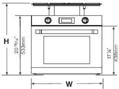
text_image
H 20 15/4" 533mm W 17 1/4" 438mmFront View Top V
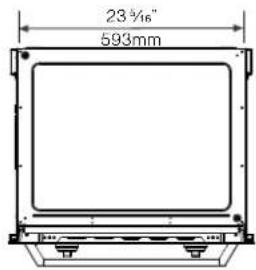
text_image
23¾" 593mm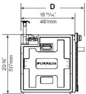
text_image
D 18 1/16" 481mm 20%" 517mm FURIONSide View
General Specifications
| BTU/HR | 9,000 BTU |
| Fuel | Propane Gas |
| Inlet Pressure | 10" WCI Min to 13.8" WCI Max |
| Power Input | 12 VDC < 2amp |
| Inner Volume of the Oven | 58L |
| Overall Dimension (W x H x D) | 24 34 "x 25 78 " x 22 18 " (628 x 656 x 562mm) |
text_image
Technical diagram of an oven with numbered parts and control labelsINCENDIE, EXPLOSION, BLESSURE PAR BRÛLURE, INTOXICATION AU MONOXYDE DE CARBONE
natural_image
Technical line drawing showing a device inside a cabinet with an arrow indicating direction (no text or symbols)natural_image
Isometric line drawing of a kitchen or appliance interior with ventilation ducts and a labeled section (no text or symbols beyond label)natural_image
Technical line drawing of a solar panel installation with labeled components (no text or symbols beyond label)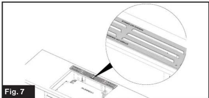
text_image
BATHLET BATHLET BATHLET Fig. 7natural_image
Technical line drawing of a structure with ventilation grilles and labeled 'FURION' (no other text or symbols)natural_image
Technical diagram of an oven or refrigerator interior showing internal structure and a black arrow indicating rotation (no text or symbols present)natural_image
Diagram of an oven with a furrion unit and airflow direction arrow, labeled Fig. 16 (no text or symbols on the diagram itself)natural_image
Technical illustration of an oven with a labeled component 'FURRION' and an arrow indicating direction (no text or symbols beyond label)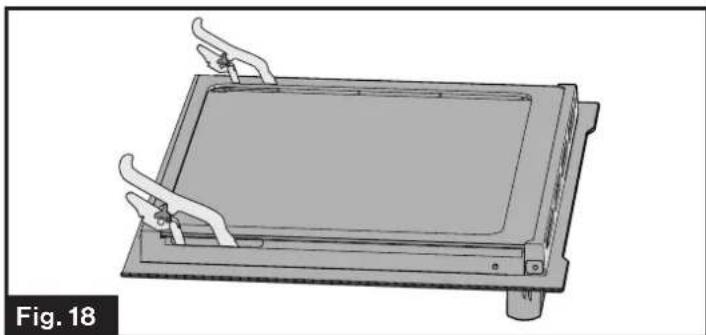
natural_image
Technical line drawing of a mechanical device with clamps and a rectangular base (no text or symbols)natural_image
Technical line drawing of a mechanical component with two circular features and directional arrows indicating motion (no text or symbols)natural_image
Technical illustration of a washing machine with an inset close-up showing the internal components (no text or symbols)natural_image
Diagram of a kitchen appliance with a close-up view showing internal components connected to a wall-mounted device (no text or symbols present)natural_image
Technical line drawing of a kitchen appliance with an inset close-up showing internal components (no text or symbols)text_image
Technical diagram of an oven with numbered parts and control labelsnatural_image
Technical line drawing showing a device inside a cabinet with an arrow indicating direction (no text or symbols)natural_image
Isometric line drawing of a kitchen or appliance interior with ventilation ducts and a labeled section (no text or symbols beyond label)natural_image
Technical line drawing of a solar panel installation with labeled components (no text or symbols beyond label)
text_image
BATHLET BATHLET BATHLET Fig. 7natural_image
Technical line drawing of a structure with ventilation grilles and labeled 'FURION' (no other text or symbols)natural_image
Technical illustration of an oven with a black arrow indicating a directional change, labeled 'Fig. 14' (no text or symbols on the diagram itself)natural_image
Diagram of an oven with a furrion unit and a door, showing internal structure and airflow direction (no text or symbols)natural_image
Technical line drawing of a mechanical device with clamps and a rectangular base (no text or symbols)natural_image
Technical line drawing of a mechanical component with two circular features and directional arrows indicating motion (no text or symbols)natural_image
Technical illustration of a washing machine with an inset close-up showing the internal components (no text or symbols)natural_image
Technical illustration of a kitchen appliance with a close-up view showing internal components (no text or symbols)natural_image
Technical line drawing of a kitchen appliance with an inset close-up showing internal components (no text or symbols)natural_image
Abstract black geometric shapes on white background (no text or symbols)FURRION
Furrion Innovation Center & Institute of Technology
- 52567 Independence Ct., Elkhart, IN 46514, USA - Toll free:1-800-789-3341
- Email: support@furrion.com
©2007-2020 Furrion Ltd. Furrion and the Furrion logo are trademarks licensed for use by Furrion Ltd. and registered in the U.S. and other countries.